1
NEC Storage Manager
Data Replication User’s Manual
(Function Guide)
IS015-9E
© NEC Corporation 2001-2004
No part of the contents of this book may be reproduced or
transmitted in any form without permission of NEC Corporation.
The contents of this book may be modified without notice in the future.
Preface
This manual describes how to use the data replication function provided by NEC Storage DynamicDataReplication
Ver2, NEC Storage RemoteDataReplication Ver2, and NEC Storage ReplicationControl.
The data replication function consists of the replication volume creation function provided in a disk array and
software to manage and operate it. It utilizes replication volume to make business operation more effective.
Refer to the “NEC Storage Manager Manual Guide” (IS901) for the overview of NEC Storage and the related
manuals.
Refer to the “NEC Storage Manager Data Replication User’s Manual (Disaster Recovery System
Installation and Operation Guide)” (IS027) for the usage of the remote data replication functions provided by NEC
Storage RemoteDataReplication/DisasterRecovery and NEC Storage ReplicationControl/DisasterRecovery.
Remarks 1. This manual explains functions implemented by the following program products:
• NEC Storage Manager and NEC Storage BaseProduct
• NEC Storage DynamicDataReplication
• NEC Storage ReplicationControl
• NEC Storage RemoteDataReplication
2. This manual is applicable to the program products of the following versions:
• NEC Storage Manager Ver3.3
• NEC Storage BaseProduct Ver3.3
• NEC Storage ReplicationControl Ver3.3
3. The NEC Storage Manager is referred to as iSM or Storage Manager in the text of this manual.
Also, the NEC Storage series disk array subsystem is referred to as a disk array.
4. The following descriptions in the text of this manual refer to the corresponding products.
Description
Corresponding Product
Storage Manager
NEC Storage Manager
AccessControl
NEC Storage AccessControl
DynamicDataReplication
NEC Storage DynamicDataReplication
RemoteDataReplication
NEC Storage RemoteDataReplication
RemoteDataReplication/DisasterRecovery
NEC Storage RemoteDataReplication/DisasterRecovery
ReplicationControl
NEC Storage ReplicationControl
SnapControl
NEC Storage SnapControl
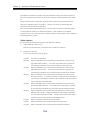
5. The following descriptions in the text of this manual refer to the corresponding manuals.
Description
Corresponding Manual
User's Manual (UNIX)
NEC Storage Manager User's Manual (UNIX) (IS001)
User's Manual
NEC Storage Manager User's Manual (IS004)
Configuration Setting Tool User’s
Manual (GUI)
NEC Storage Manager Configuration Setting Tool User’s
Manual (GUI) (IS007)
Data Replication User’s Manual
(Installation and Operation Guide for
Windows)
NEC Storage Manager Data Replication User’s Manual
(Installation and Operation Guide for Windows) (IS016)
Data Replication Command Reference
NEC Storage Manager Data Replication Command
Reference (IS021)
Description
Corresponding Product
Data Replication User’s Manual (Disaster NEC Storage Manager Data Replication User’s Manual
Recovery System Installation and
(Disaster Recovery System Installation and Operation
Operation Guide)
Guide) (IS027)
Snapshot User’s Manual (Function
Guide)
NEC Storage Manager Snapshot User’s Manual (Function
Guide) (IS030)
6. Trademarks and registered trademarks
• Microsoft® and Windows® are trademarks or registered trademarks of Microsoft Corporation in the
United States and other countries.
• HP-UX is a registered trademark of Hewlett-Packard Co. in the United States.
• UNIX is a registered trademark of The Open Group in the United States and other countries.
• VERITAS, VxVM, VxFS, NetBackup, VERITAS Volume Manager, VERITAS File System, and
VERITAS NetBackup are trademarks or registered trademarks of VERITAS Software Corporation in
the United States and other countries.
• Legato NetWorker is a registered trademark of Legato Systems, Inc. in the United States.
• Sun is a registered trademark of Sun Microsystems, Inc. in the United States and other countries.
• Solaris is a trademark or a registered trademark of Sun Microsystems, Inc. in the United States and
other countries.
• Linux is a trademark or registered trademark of Mr. Linus Torvalds in the United States and other
countries.
• AIX is a trademark of IBM Corporation.
Other product names and company names, etc. are trademarks or registered trademarks of the
associated companies.
7. In this document, matters to which careful attention needs to be paid will be described as follows:
Be sure to observe the contents.
If the indications are ignored and the system is improperly operated, settings which have been already
made might be affected.
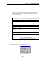
Type of Indication
Type
Description
Describes contents which require special attention during operation.
The First Edition in March 2003
The Ninth Edition in November 2004
Contents
Chapter 1
Data Replication Overview ...............................................................................................................................1
1.1
Data Replication ..........................................................................................................................................................1
1.2
Examples of Applying Data Replication.....................................................................................................................2
1.2.1
Backup .................................................................................................................................................................2
1.2.2
Test Environment Setting ....................................................................................................................................4
1.2.3
Parallel Processing of Search Operation .............................................................................................................5
1.3
System Configuration..................................................................................................................................................6
Chapter 2
Data Replication ................................................................................................................................................8
2.1
Volume Classification .................................................................................................................................................8
2.2
Replication Operations ..............................................................................................................................................10
2.2.1
Replicate ............................................................................................................................................................10
2.2.2
Separate .............................................................................................................................................................10
2.2.3
Restore ...............................................................................................................................................................11
2.3
Replication Operations and State Transitions ...........................................................................................................12
2.3.1
Replicate and State Transitions .........................................................................................................................13
2.3.2
Separate and State Transitions ..........................................................................................................................14
2.3.3
Restore and State Transitions ............................................................................................................................15
2.3.4
Activity State and Synchronous State ...............................................................................................................16
2.4
Copy Control State ....................................................................................................................................................17
2.5
Relationship between Copy Performance and Copy Control State...........................................................................19
2.6
RV Access Restriction...............................................................................................................................................20
2.7
Copy Faults and State Transitions.............................................................................................................................21
2.8
Freeze of Disk Arrays................................................................................................................................................22
Chapter 3
3.1
Replication Management ................................................................................................................................23
Replication Management Overview ..........................................................................................................................23
3.1.1
Operations and Authorization Levels................................................................................................................23
3.1.2
Event Detection and Operation Message Output ..............................................................................................24
3.1.3
Notes on Operation............................................................................................................................................26
3.2
Explanation of Replication Screen ............................................................................................................................27
3.2.1
Replication Screen.............................................................................................................................................27
3.2.2
Configuration Display Area ..............................................................................................................................28
3.2.3
Replication Information Screen.........................................................................................................................30
3.2.4
Disk Array LINK Information Screen...............................................................................................................36
3.2.5
Menu Item List ..................................................................................................................................................39
3.2.6
Information Displayed on Execution Dialog.....................................................................................................41
3.3
Various Operations of Replication Management ......................................................................................................43
i
3.3.1
Pair Setting/Unpair ............................................................................................................................................43
3.3.2
Replicate ............................................................................................................................................................50
3.3.3
Separate .............................................................................................................................................................54
3.3.4
Restore ...............................................................................................................................................................58
3.3.5
Suspend/Resume Copy ......................................................................................................................................63
3.3.6
Change to Background Copy.............................................................................................................................68
3.3.7
RV Mode Change ..............................................................................................................................................71
3.3.8
Forced Separate .................................................................................................................................................74
3.3.9
Forced Unpair ....................................................................................................................................................78
3.3.10
Freeze/Defreeze .................................................................................................................................................82
3.3.11
Background Copy Level Change.......................................................................................................................83
3.3.12
Connection Screen.............................................................................................................................................85
3.3.13
CSV Output of Information List Display ..........................................................................................................91
3.3.14
Save Pair Setting Information ...........................................................................................................................93
3.3.15
Environment Setting ..........................................................................................................................................95
3.3.16
Refresh...............................................................................................................................................................95
3.3.17
Record Screen Information................................................................................................................................96
3.3.18
Display Disk Array Properties...........................................................................................................................97
3.3.19
Display Link Properties.....................................................................................................................................98
3.3.20
Display Copy Fault List...................................................................................................................................101
Chapter 4
Functions of ReplicationControl ..................................................................................................................103
4.1
Command List .........................................................................................................................................................104
4.2
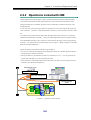
Operation Types ......................................................................................................................................................105
4.2.1
Direct Operation for a Disk Array...................................................................................................................106
4.2.2
Operations Linked with iSM ...........................................................................................................................109
4.3
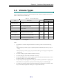
Volume Types .........................................................................................................................................................111
4.4
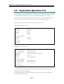
Replication Operation File ......................................................................................................................................112
4.5
Volume List Creation/Display.................................................................................................................................113
4.5.1
Command Operations (Windows) ...................................................................................................................113
4.5.2
Command Operations (UNIX) ........................................................................................................................119
4.5.3
GUI Operations (Windows) ............................................................................................................................124
4.6
Replication Operations ............................................................................................................................................140
4.6.1
Replicate Command ........................................................................................................................................140
4.6.2
Separate Command..........................................................................................................................................146
4.6.3
Restore Command ...........................................................................................................................................151
4.6.4
Copy Control State Change Command ...........................................................................................................157
4.6.5
Wait Command................................................................................................................................................161
4.6.6
Replication State Display Command...............................................................................................................165
4.6.7
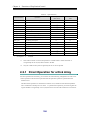
Specific Volume Name Display Command.....................................................................................................169
4.7
Pair Setting and Unpair Operations.........................................................................................................................172
ii
4.7.1
Logical Disk Information Display Command .................................................................................................172
4.7.2
Pair/Unpair Command.....................................................................................................................................175
4.8
Disk Array Operations.............................................................................................................................................178
4.8.1
4.9
Command for Displaying Information on the Replication Function...............................................................178
Disk Operations.......................................................................................................................................................181
4.9.1
File System Flush Command...........................................................................................................................181
4.9.2
Volume Mount Command ...............................................................................................................................183
4.9.3
Volume Unmount Command...........................................................................................................................185
4.9.4
Disk Signature Operation Command...............................................................................................................187
4.9.5
Devices Scan Command..................................................................................................................................189
Index
.........................................................................................................................................................................190
iii
This page is intentionally left blank.
iv
Chapter 1 Data Replication Overview
Chapter 1 Data Replication Overview
To manage an enormous amount of information accumulated in business in a unified way and promote effective
and efficient utilization of the information, a high-throughput, large-capacity, and high-reliability storage system is
required.
Data Replication provides functions to build and manage such a storage system.
This chapter describes overview of Data Replication, hardware configuration, and software configuration.
11..11 D
Daattaa R
Reep
plliiccaattiio
on
n
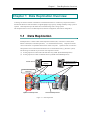
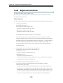
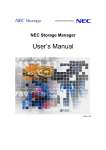
Data Replication is a function that creates Replication Volumes (RV) of a business volume (called
Master Volume (MV) in the data replication).
It is installed in the disk array. Replication volumes
can be connected to or separated from the master volume at any time.
Operations such as connection
and separation can be instructed from the business server and the iSM Client (e.g. Windows system).
The following two methods are provided to create replication volumes.
(1) Creating replication volumes within the same disk array (DDR: DynamicDataReplication)
(2) Creating replication volumes in different disk arrays (RDR: RemoteDataReplication)
Master Server
Production Task
(Online)
Parallel Processing
(Backup/Search)
Synchronize/Separate
Operation
Master
(MV)
Master
(MV)
Replication
(RV)
Replication
(RV)
DynamicDataReplication
Figure 1-1
RemoteDataReplication
Data Replication
1
Chapter 1 Data Replication Overview
11..22 E
Exxaam
mp
plleess o
off A
Ap
pp
pllyyiin
ng
gD
Daattaa
R
Reep
plliiccaattiio
on
n
When you introduce Data Replication and use replication volumes which can be separated, you can get
the following benefits.
• The system down time during data backup is largely reduced.
Lowered access performance to the
business database during data backup in system operation can be prevented.
• A test environment using the actual business data can be built more easily.
• Processing becomes more efficient due to parallel processing of data update tasks and data reference
tasks.
In this way, Data Replication makes system construction and system management easier and more
effective.
The following sections illustrate some applications of Data Replication.
11..22..11 B
Baacckkuupp
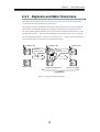
This section describes an application for backup using replication volumes.
[Backing Up from the Replication Volume to Magnetic Tape Media]
In this method, a replication volume of the master volume is backed up to the magnetic tape.
In this case, operations are suspended only for the time it takes to separate replication volumes from the
master volume. Therefore, the suspension time can be substantially reduced.
Because backup is done from the replication volume, it does not affect the master volume.
Backup Server
Master Server
Tape
Master
(MV)
Production Task
Backup
Connect
Separate
Replication
(RV)
Figure 1-2 Backup from Replication Volume
2
Chapter 1 Data Replication Overview
The procedure for backup from a replication volume is described below.
(1)
During operation, the master volume (MV) and replication volume (RV) are connected.
(2)
Suspend the production task and separate the replication volume (RV).
Resume the task after
separation is complete.
(3)
Use the separated replication volume (RV) to perform backup and the task in parallel.
After
backup is complete, reconnect the replication volume (RV) (Reconnection takes only a short time
because only updated parts in the master volume are reflected to the replication volume (RV)).
[Using the Replication Volume as Disk Backup]
In this method, the replication volume is used as backup of the master volume.
In this case, you do
not have to manage the existing magnetic tapes because they are not used as storage media.
When the restoration instruction is complete, you can use the backup data even if the actual data
replication has not been completed.
If data to be accessed is not restored to the master volume, the
data in the replication volume is accessed.
The user does not have to be aware of using which of the
master volume or replication volume.
This reduces the data restoration time substantially.
Connect
Replication 1
(RV1)
Separate
Master
(MV)
Replication 1
(RV1)
Master
(MV)
Separate
Connect
Replication 2
(RV2)
Figure 1-3
Replication 2
(RV2)
Using Replication Volume as Backup
The procedure for using a replication volume for backup is described below.
(1)
Connect the replication volume 1 (RV1) to the master volume.
(2)
Suspend the production task and separate the replication volume 1 (RV1).
Resume the task after
connecting the replication volume 2 (RV2).
(3)
After that, use the replication volume 1 (RV1) and replication volume 2 (RV2) alternately to
perform backup.
3
Chapter 1 Data Replication Overview
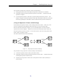
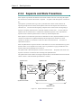
11..22..22 TTeesstt E
Ennvviirroonnm
meenntt S
Seettttiinngg
You can set the same environment as the production task environment easily by creating replication
volumes using the Data Replication function. You can evaluate an application program by using data
used in the production task, which makes evaluation of application programs more efficient.
Furthermore, in building an evaluation environment, operations are suspended only for the time which
takes to separate replication volumes from the master volume. Therefore, the suspension time can be
substantially reduced.
Test
Production
Production
Task
Task
Master
(MV)
Master
(MV)
Replication
(RV)
Connect
Replication
(RV)
Separate
Figure 1-4
Test Environment Setting
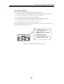
The procedure for using a replication volume as a test environment is described below.
(1)
Connect the master volume (MV) and replication volume (RV).
(2)
Suspend the production task, separate the replication volume (RV), and then resume the task.
(3)
Perform evaluation of the application program by using the separated replication volume (RV).
4
Chapter 1 Data Replication Overview
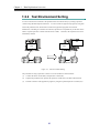
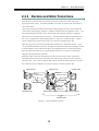
11..22..33 P
Paarraalllleell P
Prroocceessssiinngg ooff S
Seeaarrcchh
O
Oppeerraattiioonn
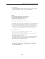
By creating replication volumes of the master database, you can separate the database and carry out
update tasks and search tasks using different volumes.
This allows you to carry out database update
tasks without affecting database search tasks.
Daytime
Nighttime
Search Task
Update Task
Master
(MV)
Connect
Master
Database
Separate
Master
(MV)
Replication
(RV)
Reflection of
Updated Parts
Figure 1-5
Master
Database
Replication
(RV)
Data for Previous
Day
Parallel Processing of Search Task
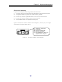
The procedure for parallel processing of search operation is described below.
(1)
In the nighttime, suspend search tasks and connect the master volume (MV) and replication
volume (RV).
(2)
In the daytime, separate the master volume (MV) and replication volume (RV).
update tasks and search tasks in parallel (RV contains data for the prior day).
5
Then perform
Chapter 1 Data Replication Overview
11..33 S
Syysstteem
mC
Co
on
nffiig
gu
urraattiio
on
n
Business Server
Backup Server
Backup Software
ReplicationControl
Tape Drive
ReplicationControl
Management
Server
DB
Replication
• AccessControl
LAN
• DynamicDataReplication
• RemoteDataReplication
Storage Manager
Disk Array
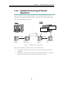
Figure 1-6
System Configuration
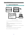
To install and use the Data Replication function, the following hardware devices are required.
• Disk array
Disk arrays on which the Data Replication function either with DynamicDataReplication or
RemoteDataReplication is installed are required.
• Management server
iSM is installed in the management server that monitors disk arrays.
This server controls disk arrays
and the Data Replication function.
• Business server/backup server
Performs Data Replication operation or backup operation in cooperation with business.
Software to run Data Replication consists of the following components.
6
Chapter 1 Data Replication Overview
• Storage Manager
Provides the disk array configuration and state display functions.
Installing DynamicDataReplication and/or RemoteDataReplication allows the replication
management function (hereinafter, referred to as the Replication Management) incorporated in iSM.
The Replication Management provides setting and operating functions such as state display, pair
setting, and replication operation for DynamicDataReplication or RemoteDataReplication.
• ReplicationControl
Provides commands for checking replication operations and replication states from the business
server and also provides library functions.
• AccessControl
The function to set the logical disks that can be accessed, for each business server.
• DynamicDataReplication
The function to realize data replication within the same disk array.
• RemoteDataReplication
The function to realize data replication in the different disk arrays.
7
Chapter 2 Data Replication
Chapter 2 Data Replication
This chapter describes the types and state transitions of volumes that are necessary to perform operation using the
Data Replication function.
22..11 V
Vo
ollu
um
mee C
Cllaassssiiffiiccaattiio
on
n
To create replication volumes using the Data Replication function, you must set the relation between
the original volume and the target volume (replication volume) first.
In replication control, the
original volume is called MV (Master Volume), and replication volume is called RV (Replication
Volume).
Furthermore, MV and RV are set as a pair.
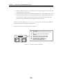
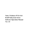
In a disk array to which the Data Replication function is installed, the volume classification in the disk
array is categorized into the following three types.
Figure 2-1 describes sample volume classification.
• Isolated Volume (IV)
Volume with no pair setting.
By specifying the pair setting to IV, you can set it to MV or RV.
• Master Volume (MV)
Volume with the pair setting. The original volume in the pair. Normally, volumes used in
operation are set as MVs.
To distinguish the uppermost MV from other MVs when multiple pairs are set in series hierarchically,
it is called the Primary Volume (PV).
• Replication Volume (RV)
Volume with the pair setting. The target volume in the pair.
Normally, volumes used as backup or
in test operation are set as RVs.
The pair setting can be between the volumes within the same disk array, or between the volumes in
different disk arrays.
To distinguish them, the former is called a Dynamic Replication Volume
(dRV) and the latter is called a Remote Replication Volume (rRV).
8
Chapter 2 Data Replication
Disk Array A
Disk Array B
FC
A1
A2
B1
IV
IV
IV
A3
MV
(PV)
A4
RV/MV
(dRV)
B2
RV
(rRV)
Pair Setting
Volume
A1/A2/B1
: IV
Volume
A3
: MV (PV) of the pair A3/A4
Volume
A4
: RV (dRV) of the pair A3/A4, and MV of the pair A4/B2
Volume
B2
: RV (rRV) of the pair A4/B2
Figure 2-1
Example of Volume Classification
9
Chapter 2 Data Replication
22..22 R
Reep
plliiccaattiio
on
nO
Op
peerraattiio
on
nss
The replication operations include Replicate that replicates data from MV to RV, Separate that
separates between MV and RV, and Restore that replicates data from RV to MV.
22..22..11 R
Reepplliiccaattee
This operation copies data from MV to RV.
It is performed to replicate the latest data to the replication volume used in a test environment or search
tasks. When Replicate is executed, the data in MV is copied to RV.
In addition, any update made to
MV after Replicate is reflected to RV.
22..22..22 S
Seeppaarraattee
This operation separates MV and RV.
It is performed to suspend data replication between MV and RV to use RV in a test environment or
search tasks.
When Separate is started, all the difference between the MV and RV contents at the point of starting
Separate is reflected into the RV, and then data replication is suspended and the RV is separated. The
updates made to MV after starting Separate are not reflected to RV and stored in the disk array as
update differences.
When executing Separate, you can determine when to make the RV available by choosing either of the
following:
• Separate for making RV available after completion of separation: Separate(completion)
Reflects all the difference between the MV and RV contents into the RV, and makes the RV available
after completion of separation.
Even though Separate is executed immediately after Replicate starts, RV cannot be used while the
difference between MV and RV is being reflected to RV.
RV becomes available upon completion
of separation.
• Separate for immediately making RV available: Separate(immediate)
While reflecting the difference between the MV and RV contents into the RV, the Separate function
makes the RV available even during separation. You can instantly create RV and make it available
by executing Separate(immediate).
This function is available only for performing data replication in the same disk array.
“DynamicDataReplication Ver2“ is necessary for using the function.
10
The product
Chapter 2 Data Replication
22..22..33 R
Reessttoorree
This operation copies data from RV to MV.
It is performed to restore data from the backup volume (RV) when a failure occurs in MV.
When Restore is executed, the RV contents at the point of starting Restore are reflected copied into the
MV.
At this time, you can determine whether to reflect the updated data of the MV into the RV by
choosing either of the following:
• Restore with RV being updated: Restore(update)
Restores the MV while automatically reflecting the updated data of the MV into the RV.
Even after
the difference between MV and RV is resolved and Restore is completed, any data update made to
MV is reflected to RV.
• Restore without RV being updated: Restore(protect)
Restores the MV without reflecting the updated data of the MV into the RV.
After the difference
between MV and RV is resolved and Restore is completed, Separate is automatically executed.
The
Restore(protect) function enables you to save the RV data in the state before the restoration.
The product DynamicDataReplication Ver2 or RemoteDataReplication Ver2 is necessary for using
the function.
11
Chapter 2 Data Replication
22..33 R
Reep
plliiccaattiio
on
nO
Op
peerraattiio
on
nss aan
nd
dS
Sttaattee
T
nssiittiio
on
nss
Trraan
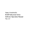
This section describes the replication operations and state transitions.
The pair setting is specified
but MV and RV are separated.
separated
Difference between MV and
RV is being reflected.
MV
sync
RV
Replicate
• RV cannot be updated.
• MV and RV can be
updated.
The pair setting is specified
and synchronization has been
established.
rpl/exec
• Updates to MV are reflected to RV.
• As a rule, access to RV is not
allowed.
rpl/sync
sep/exec
MV
RV
Separate
• As a rule, RV cannot
be updated.
MV
RV
rst/sync
rst/exec
Restore
• RV cannot be updated.
MV
RV
exec : Executing Replicate, Separate, or Restore
sync : Replicate or Restore synchronization state
rpl : replicate (Replicate)
rpl/exec ............. Executing synchronization
rpl/sync ............. Synchronization state
sep : separate (Separate)
sep/exec ............ Executing Separate
separated .......... Separate completion state
rst : restore (Restore)
rst/exec ............. Executing Restore
rst/sync ............. Synchronization state
Figure 2-2
• When Restore(update) is
executed, updates to MV are
reflected to RV.
• When Restore(protect) is
executed, updates to MV are not
reflected to RV.
• As a rule, access to RV is not
allowed.
• When Restore(protect) is executed,
Synchronous State (rst/sync) is
placed and then automatically
changed to Separated State
(separated).
Replication Operations and State Transitions
12
Chapter 2 Data Replication
22..33..11 R
Reepplliiccaattee aanndd S
Sttaattee TTrraannssiittiioonnss
When Replicate is performed, data copy from MV to RV starts to reflect the content of MV to RV.
Any update to MV after Replicate is also reflected to RV.
After Replicate is started, the difference between MV and RV gradually decreases, and eventually the
content of MV at the beginning of Replicate is completely reflected to RV (The difference is zero).
The state from the beginning of Replicate to the content of MV is completely reflected to RV is called
the “Replicate execution”. The state where the difference between MV and RV is zero is called the
state synchronized by Replicate, or simply the “synchronous state“.
Replicate execution and the state
synchronized by Replicate are collectively called the Replicate state.
Update to MV
Update to MV
MV
Replicate
operation starts
RV
MV
Until the
difference is zero
RV
Separate State
Replicate State
Replicate and State Transitions
13
MV
RV
Synchronous Execution
Figure 2-3
Update to MV
Synchronous State
Chapter 2 Data Replication
22..33..22 S
Seeppaarraattee aanndd S
Sttaattee TTrraannssiittiioonnss
When Separate is performed, the difference between MV and RV at the time of executing the Separate
start instruction is reflected to RV and RV is separated.
No update to MV after Separate is reflected to
RV.
After Separate is performed, data copy to RV is performed if the contents of MV and RV at the
beginning of Separate do not match, and all updates to MV before the Separate start instruction are
reflected to RV.
The state from the beginning of Separate to the content of MV at the beginning of
Separate is completely reflected to RV is called the “Separate execution state“. The state where all
updates to MV are reflected to RV is called the state separated by Separate, or the “separated state“.
Separate execution and the separated state are collectively called the Separate state.
When Separate is executed under specification of immediate use of RV (Separate(immediate)), the RV
contents can be referred to or updated immediately after the Separate start instruction is issued,
regardless of whether or not all the MV contents have been reflected into the RV. This feature is
implemented as follows.
When an update/reference request for the RV is made and access to an area where difference copy from
the MV into RV is not completed is to be made, control is performed for copying the difference from
the MV into RV before permitting access to the area.
The updates made to MV until Separate is started are reflected to RV.
The updates made to MV after
Separate is started are not reflected to RV and managed as update difference.
The updated states of MV and RV are managed in Separate State so that the difference between the MV
and RV contents is reflected when Replicate/Restore is executed.
Update to MV
Update to MV
MV
Separate
operation starts
MV
Until the difference
between MV and
RV is fully reflected
to RV
Update to MV
MV
RV
RV
RV
Synchronous State
Separate Execution
Separated State
Separate State
Figure 2-4
Separate and State Transitions
14
Chapter 2 Data Replication
22..33..33 R
Reessttoorree aanndd S
Sttaattee TTrraannssiittiioonnss
When Restore is performed, data copy from RV to MV starts to reflect the content of RV at the
beginning of Restore to MV. When Restore(update) is executed, any update to MV after Restore is
also reflected to RV.
After Restore is started, the difference between MV and RV gradually decreases, and eventually the
content of RV at the beginning of Restore is completely reflected to MV (The difference is zero). The
state from the beginning of Restore to the content of RV at the beginning of Restore is completely
reflected to MV is called the “Restore execution”. The state where the difference between MV and
RV is zero is called the state synchronized by Restore, or simply the “synchronous state“.
Restore
execution and the state synchronized by Restore are collectively called the Restore state.
When Restore(protect) is executed, the updated data of the MV is not reflected into the RV.
In this
case, the updated information of the MV is managed as the difference between the MV and RV contents
so that the difference can be reflected into the RV when Replicate/Restore is executed subsequently.
When the Synchronous State (sync) is placed after Restore(protect) is executed, it is automatically
changed to the Separated State (separated).
When data of MV is referred to during Restore execution, the user can refer to the content of RV
immediately after the instruction to start Restore even if the content of RV has not been completely
reflected to MV.
This is done by obtaining data from RV when the area where difference copy from
RV to MV has not been completed is accessed in response to a reference request to MV.
Update to MV
MV
Update to MV
Restore
operation starts
MV
RV
RV
Separate State
Restore Execution
Until the
difference is zero
MV
Only when
updating RV
Restore and State Transitions
15
RV
Synchronous State
Restore State
Figure 2-5
Update to MV
Chapter 2 Data Replication
22..33..44 A
Accttiivviittyy S
Sttaattee aanndd S
Syynncchhrroonnoouuss
S
Sttaattee
In data replication, Replicate, Restore, and Separate states are called “activity states”, or simply
“activities”.
The execution states indicating state transitions and the state in which the state transition is complete
are called “synchronous states”.
Table 2-1 shows the activity states and synchronous states which transit as a result of each replication
operation.
For information on handling MV and RV access in the activity states, refer to 2.6 “RV
Access Restriction”.
Activity State
Separate State
Table 2-1 Activity State and Synchronous State
Synchronous State
Description
Separate Execution
(sep/exec)
Separated(separated)
Replicate State
Restore State
• Temporal state until the difference between MV and RV
becomes zero after Separate
• As a rule, read and write to RV are not allowed.
• Data copy between MV and RV is not performed. This
state occurs immediately after the pair setting.
• Normally, read and write to RV are allowed.
Forced Separate(cancel)
• MV and RV are forcibly separated by Forced Separate.
• Read and write to RV are allowed.
Failure Separation (fault)
• MV and RV are forcibly separated in the disk array due
to a copy fault.
• Read and write to RV are allowed.
Synchronous Execution
(rpl/exec)
• Reflection of the difference between MV and RV at
Replicate has not been completed (The difference is
being reflected from MV to RV).
• Updates to MV is reflected to RV.
• As a rule, read and write to RV are not allowed.
Synchronous State(rpl/sync)
• Reflection of the difference between MV and RV at
Replicate has been completed.
• Updates to MV is reflected to RV.
• As a rule, read and write to RV are not allowed.
Restore Execution(rst/exec)
• Reflection of the difference between MV and RV at
Restore has not been completed (The difference is being
reflected from RV to MV).
• When Restore(update) is executed, the updated data of
the MV is reflected into the RV.
• When Restore(protect) is executed, the updated data of
the MV is not reflected into the RV.
• As a rule, read and write to RV are not allowed.
Synchronous State(rst/sync)
• Reflection of the difference between MV and RV at
Restore has been completed.
• When Restore(update) is executed, the updated data of
the MV is reflected into the RV.
• When Restore(protect) is executed, the updated data of
the MV is not reflected into the RV and the Separate
completion state is automatically entered.
• As a rule, read and write to RV are not allowed.
16
Chapter 2 Data Replication
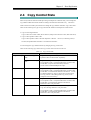
22..44 C
Co
op
pyy C
Co
on
nttrro
oll S
Sttaattee
If the activity between volumes with the pair setting is the Replicate or Restore state, you can change the
copy method of data between MV and RV according to the load status of the disk array. The state to
which a transition is made by the instruction to change the copy method is called the “copy control state“.
There are the following two types of copy between MV and RV in the Replicate or Restore state.
• Copy for reflecting difference
Copy to reflect the content of MV (RV for Restore) at Replicate or Restore to RV (MV for Restore).
• Copy to reflect updates in MV to RV
Copy to reflect updates in MV to RV after Replicate or Restore. However, if Restore(protect) is
executed, the updated data of the MV is not reflected into the RV.
You can change the copy method and state by changing the copy control state.
There are the following copy states in the copy control states as shown in Table 2-2.
Table 2-2 Copy Control State
Copy Control State
Foreground Copy
Copy State
Synchronous Copy
Mode
• Copy for reflecting difference is performed.
Semi-synchronous Copy
Mode
• Copy for reflecting difference is performed.
• Updates to MV are reflected RV sequentially.
• I/O of updates to MV is completed when data is written to MV,
and the data is copied to RV immediately after that.
• Can be set for a RemoteDataReplication pair.
Background Copy
-
• Copy for reflecting difference is performed.
• I/O of updates to MV is completed when data is written to MV,
and the data is accumulated as difference information. For the
accumulated difference, data is copied to RV asynchronously.
The copy interval to RV (Background Copy Level) can be
changed in units of disk arrays.
Suspend
Suspend
• Copy for reflecting difference is not performed.
• I/O of updates to MV is completed when data is written to MV,
and the data is accumulated as difference information.
Reflection to RV is not performed.
Suspend due to a failure
• Forcefully suspended in the disk array due to a copy fault.
• Copy for reflecting difference is not performed.
• I/O of updates to MV is completed when data is written to MV,
and the data is accumulated as difference information.
Reflection to RV is not performed.
17
Chapter 2 Data Replication
Copy control states can be specified when Replicate or Restore is performed.
You can also change the
copy control state you specified at Replicate or Restore as required.
When Restore with RV protection specified is executed, only copy for reflecting the difference is
executed, thus the updated data of the MV is not reflected into the RV.
Therefore, specifying or
changing a copy control state (Synchronous Copy Mode, Semi-synchronous Copy Mode, or
Background Copy) has no effect.
There are the following five instructions to change the copy control state.
• Synchronous Copy instruction
• Semi-synchronous Copy instruction
• Resume instruction
• Background Copy instruction
• Suspend instruction
The Resume instruction changes Background Copy or Suspend to preceding Foreground Copy
(Synchronous Copy Mode, Semi-synchronous Copy Mode).
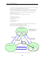
Figure 2-6 shows the state transition diagram of the copy control states.
Foreground Copy
Sync Copy
Mode
* Semi-synchronous Copy Mode
can be used only for a
RemoteDataReplication pair
Semisynchronous
Copy Mode*
Background
Copy Instruction
Suspend Instruction
Synchronous Copy or
Semi-synchronous
Copy or Resume
Synchronous Copy or
Semi-synchronous Copy
or Resume Instruction
Copy Fault
Suspend
Background Copy
Background Copy Instruction
normal
Suspend Instruction
Figure 2-6
State Transition Diagram of Copy Control State
18
abnormal
Chapter 2 Data Replication
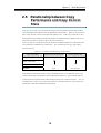
22..55 R
Reellaattiio
on
nssh
hiip
pb
beettw
weeeen
nC
Co
op
pyy
P
Peerrffo
orrm
maan
nccee aan
nd
dC
Co
op
pyy C
Co
on
nttrro
oll
S
Sttaattee
If the copy control state is set to the Synchronized Copy state, the difference between MV and RV is
not accumulated because updates to MV are immediately reflected to RV.
However, the write time to
MV is longer because it waits for reflection of the updates to RV. If the Copy Control state is set to
the Suspend state, the difference between MV and RV is accumulated because updates to MV are not
reflected to RV, but the write time to MV is the same as normal I/O.
In this way, there are correlations between the amount of accumulated differences in MV and RV and
write performance in different copy control states. The correlation for each copy control state is
shown in Table 2-3.
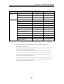
Table 2-3
Copy Control State
Correlations in Different Copy Control States
Difference between MV and RV
Write Overhead to MV
Small
Exists
Large
Does not exist
Foreground (Synchronous)
Foreground
(Semi-synchronous)
Background
Suspend
If the difference between MV and RV is large in the Replicate state, we recommend to select a copy
control state which gives the difference between MV and RV smaller in a system without sufficient
suspension time for Separate execution because the processing time of Separate increases.
Also, we
recommend you to select a copy control state without write overhead to MV in a system where write
performance to MV must be maintained and improved.
19
Chapter 2 Data Replication
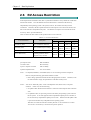
22..66 R
RV
VA
Acccceessss R
Reessttrriiccttiio
on
n
In the Replicate state and Restore state, MV is synchronized with RV to always match the volume data
between MV and RV.
Since the difference between MV and RV is reflected in the disk array
independently of the operating system or file system, however, the volume of RV may become
inconsistent.
Therefore, the data replication function cannot impose access restrictions for MV, and
MV can be referred to and updated at any time. The function can impose access restrictions for RV
for activity state to prevent malfunction.
Table 2-4 shows the states which can be specified as RV access restrictions.
Table 2-4 RV Access Restriction
Access Restriction
Description
Read/Write (R/W)
RV is enabled for read/write.
Read Only (RO)
RV is enabled only for reading.
Not Ready (NR)
RV is disabled for read/write.
Not Available (NA)
RV is not recognized by the
operating system or the LU
(Logical Unit) is invalid.
Activity State
rpl
rst
sep/exec
separated
-
-
∆
Note 1
{
∆
Note 2
∆
Note 2
∆
Note 2
∆
Note 3
{
{
{
-
∆
Note 4
∆
Note 4
∆
Note 4
∆
Note 4
∆: Available with administrative restrictions
{: Available
rpl: Replicate state
RW: Read/Write
rst: Restore state
RO: Read Only
sep/exec: Separate execution
NR: Not Ready
separated: Separated state
NA: Not Available
-: Unavailable
Note 1: For Separate(immediate), “Read/Write (RW)” is set even during execution of Separate.
However, keep the following operational influence in mind:
1. Data is being copied from the MV into RV during Separate execution.
Therefore, if the
I/O load on the RV is high, I/O performance on the MV side may lower.
Note 2: You can set “Read Only (RO)” to RV in the Replicate state, Restore state, or Separate
execution.
In this case, note the following.
1. No update to MV should be done when RV is referred to in the Replicate state or Restore
state.
2. For updates to MV, I/O processing is done to the disk by the operating system control of
the file system. Even if the application has completed the update process to the disk, it
has not necessarily completed the update process to MV.
Reflection of the update to RV
is processed in the disk array independent of the operating system.
Therefore, RV cannot be referred to normally because it is not consistent as a volume.
You can use it if consistency is assured in the specific operation.
20
Chapter 2 Data Replication
Note 3: If “Read Only (RO)” is set for RV for which Separate was completed, keep the following
operational notes in mind.
<On the Windows system>
1. If NTFS is used as a file system, reference to the RV is disabled.
2. If FAT16/FAT32 is used as a file system, associate the file system with the drive by using
the mount command of the disk control operation commands or by starting [Disk
Management] (Windows).
3. If FAT16/FAT32 is used as a file system, an attempt to write to RV ends up with an error.
Therefore, do not use any application for automatically performing write operation for the
drive.
Do not perform any operation (e.g., changing of a partition configuration) in
which write to RV is performed through [Disk Management] (Windows).
<On the UNIX system>
When mounting a file system, it is necessary to mount it by a read-only specification.
Note 4: The “Not Available (NA)” state has meaning when the VSS (Volume Shadow copy Service)
function is used. A transition to the Not Available state is automatically controlled by the
VSS function. The user need not perform the operation normally.
22..77 C
Co
op
pyy F
Faau
ullttss aan
nd
dS
Sttaattee T
Trraan
nssiittiio
on
nss
If copy operation between MV and RV is not performed normally due to a connection failure between
them, a transition to the following states may occur depending on the timing and type of the failure.
• Separate state due to a fault (failure separation)
Forcefully separated in the disk array due to a copy fault.
The contents of MV and RV are
completely different.
To cancel the Separate state due to a failure, remove the cause of the copy fault and perform
restoration by using Replicate and Restore.
• Suspend state due to a fault (abnormal suspend)
Forcefully suspended in the disk array due to a copy fault in the Replicate or Restore state.
Copy
between MV and RV is suspended.
To cancel the Suspend state due to a failure, change the copy control state as you do to cancel the
normal Suspend state after removing the cause of the copy fault (Refer to 2.4 “Copy Control State”).
21
Chapter 2 Data Replication
22..88 F
Frreeeezzee o
off D
Diisskk A
Arrrraayyss
If the power to the disk array is turned off for maintenance, access to the disk array is disabled,
disallowing to continue copy operation for the paired volumes in the disk array. In this situation, the
data replication function for the disk array stops replication operations of the whole disk array.
Freezing of replication operations for the disk array due to power down of the disk array is called
freezing of the disk array and the state is called the freeze state of the disk array.
When a disk array is in the freeze state, replication operations between volumes to which the pair
setting with the volume in the disk array is specified are also suspended, and the copy control state of
the pair becomes the freeze state.
When the pair is in the freeze state, no new replication operation can be performed.
For pairs in the freeze state, note the following.
• Freeze in the Separate state
If the pair goes into the freeze state in Separate execution, it transits to the Separate state due to a fault
(failure separation) when the following operation is performed.
<When updates to MV are done to the area where copy to RV has not been completed>
In this case, to use RV after the freeze state is cancelled, you must perform Replicate again to copy
data, and perform Separate.
• Freeze in the Replicate state
If the pair goes into the freeze state in the Replicate state, copy operation between MV and RV is
suspended.
Copy operation is automatically resumed when the freeze state is cancelled.
• Freeze in the Restore state
If the pair goes into the freeze state in the Restore state, I/O terminates abnormally when reference or
update is performed to the area where copy from RV to MV has not been completed.
If the pair goes into the freeze state in the restored state, copy operation between MV and RV is
suspended.
Copy operation is automatically resumed when the freeze state is cancelled.
22
Chapter 3 Replication Management
Chapter 3 Replication Management
This chapter describes various operations of Data Replication by the Graphical User Interface (GUI).
33..11 R
Reep
plliiccaattiio
on
nM
Maan
naag
geem
meen
ntt
O
Ovveerrvviieew
w
This chapter describes an overview of various operations and the management method regarding data
replication that uses the replication management function.
33..11..11 O
Oppeerraattiioonnss aanndd A
Auutthhoorriizzaattiioonn LLeevveellss
Use the following functions to perform operations related to Data Replication through the iSM Client:
• State Monitoring
• Replication manager
• Configuration setting
Since operations performed from Replication manager includes important operations on volumes, the
operating authorization is set according to the following allowance levels.
However, when the server is disconnected by State Monitoring after displaying the Replication screen,
only the currently displayed state (the information gained while the server was connected) can be
referenced regardless of the operation authorization.
• L1:
Allows only reference.
• L2:
Allows replication-related operations (copy operations) in the administration level.
• L3:
Allows all operations.
For information on how to set and log in, refer to the “User’s Manual” or “User’s Manual (UNIX)” in
accordance with your OS.
23
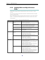
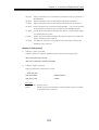
Chapter 3 Replication Management
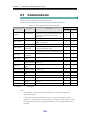
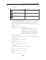
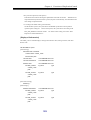
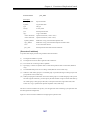
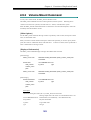
Table 3-1 lists the operations and state displays.
Table 3-1 List of Displays/Operations of Data Replication
Replication Management
Operation Item
State
Monitoring
Configuration
Setting
Display
Operation Authorization
L1
L2
L3
Set Disk Array Name
√
√
√
-
-
-
Set Logical Disk Name
√
√
√
-
-
-
Link State
-
-
√
-
-
-
Pair Setting/Unpair
-
-
√
-
-
√
Replicate
-
-
√
-
√
√
Separate
-
-
√
-
√
√
Restore
-
-
√
-
√
√
Suspend/Resume Copy
-
-
√
-
√
√
Change to Background Copy
-
-
√
-
√
√
RV Mode Change
-
-
√
-
√
√
Forced Separate
-
-
√
-
√
√
Forced Unpair
-
-
√
-
-
√
Freeze/Defreeze
-
-
√
-
-
√
Background Copy Level Change
-
-
√
-
-
√
Pair Batch Setting
-
√
-
-
-
-
√: Available
- : Not available
L1: Allows only reference.
L2: Allows replication-related operations (copy operations) in the administration level.
L3: Allows all operations.
33..11..22 E
Evveenntt D
Deetteeccttiioonn aanndd O
Oppeerraattiioonn
M
Meessssaaggee O
Ouuttppuutt
Events that occur in response to various operations performed on disk arrays and volumes can be
detected by the state monitoring and displayed in the iSM Client’s message display area as operation
messages.
By executing an environment setting beforehand, it is possible to detect events that occur as the result
of executing replication operation commands or other operations as well as performing replication
management operations, and it is also possible to confirm the events from operation messages.
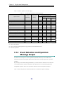
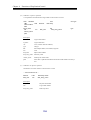
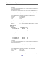
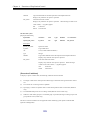
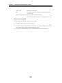
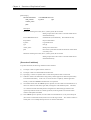
Table 3-2 shows the replication-related events that can be confirmed as operation messages:
24
Chapter 3 Replication Management
Table 3-2
List of Replication-Related Events
Replication Management
Operation
Operation
Operation Target
Disk array
Volume
{: Regular report
Other Operations
Freeze
{
∆
Defreeze
{
∆
Change Background Copy level
{
∆
Pair Setting/Unpair
{
∆
Replicate
{
∆
Synchronous State (rpl/sync)
∆
∆
Separate
{
∆
Separated
∆
∆
Restore
{
∆
Synchronous State (rst/sync)
∆
∆
Suspend/Resume Copy
{
∆
Change to Background Copy
{
∆
Change RV Mode
{
∆
Change Copy Mode
{
∆
∆: Additional report performed according to an environment setting
−: Not reported
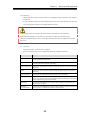
Note: Replication management operations include operations performed together with the
ReplicationControl commands.
Regarding S2100 and A2100, the detection of events other than pair setting and unpairing events
may not be possible during the state monitoring.
Furthermore, the state monitoring monitors all the disk arrays’ volumes for a specified time
interval (default: 15 seconds) to detect events.
Therefore, there is a time difference between
when an event actually occurred and when a message is output. Also, messages for each
detected event are displayed at the same time.
For information about an environment setting regarding the state monitoring’s event detection
time interval and operation message output control, refer to the “User’s Manual” or “User’s
Manual (UNIX)” in accordance with your OS.
25
Chapter 3 Replication Management
33..11..33 N
Nootteess oonn O
Oppeerraattiioonn
Note the following points when operating replication management:
[System Parameter Setting (on UNIX)]
For more information, refer to the “User’s Manual (UNIX)”.
[Messages at Start]
Immediately after iSM is started, replication-related device information is created internally.
Replication-related device information is recreated according to an information recreate instruction
from ReplicationControl.
Even if an attempt is made to display the Replication Screen at this timing, the screen cannot be
displayed because the device information cannot be obtained.
If this happens, retry to display the
screen after a while.
[Action to Be Taken at Occurrence of Problems]
Refer to dialogs (messages) or help to take appropriate action.
26
Chapter 3 Replication Management
33..22 E
Exxp
pllaan
naattiio
on
no
off R
Reep
plliiccaattiio
on
nS
Sccrreeeen
n
To perform an operation, select the volumes you want to perform the operation to in the Volume List
Displayed on the Replication Information tab in the Replication Screen, and then click the [menu] on
the menu bar. You can also right-click the volume to display the menu.
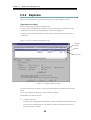
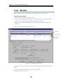
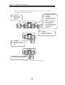
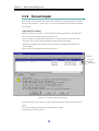
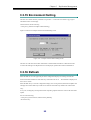
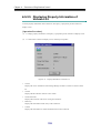
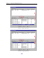
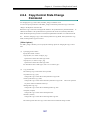
33..22..11 R
Reepplliiccaattiioonn S
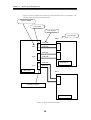
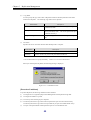
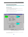
Sccrreeeenn
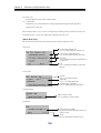
The Replication Screen consists of the configuration display area (i) on the left part of the screen
displaying the configuration and state of the disk array and the information list display area (ii) on the
right part of the screen displaying the Volume List and disk array link configuration.
When the
Replication Screen appears for the first time, it contains only the configuration display area (i) and the
information list display area (ii) is displayed by clicking the disk array icon. The information list
display area (ii) shows the selected disk array and the Volume List of the disk array connected with the
selected disk array by RemoteDataReplication.
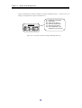
(i)
(ii)
Figure 3-1
Example of Replication Screen
(i)
For details, refer to 3.2.2 “Configuration Display Area”.
(ii)
For details, refer to 3.2.3 “Replication Information Screen” and 3.2.4 “Disk Array LINK
Information Screen”.
* For details on the AT-group information screen, refer to the “Data Replication User’s Manual
(Disaster Recovery System Installation and Operation Guide)”.
27
Chapter 3 Replication Management
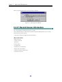
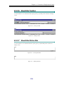
33..22..22 C
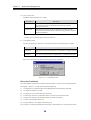
Coonnffiigguurraattiioonn D
Diissppllaayy A
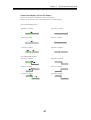
Arreeaa
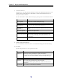
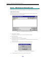
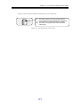
The configuration display area is under the monitoring by the iSM and displays the list and the state of
the Disk Arrays that can use the Replication function, as well as the status of link among them.
Figure 3-2
Example of Configuration Display Area
28
Chapter 3 Replication Management
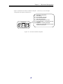
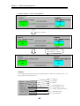
Disk Array icon
Icon
,
,
(in colors)
Description
, etc. Indicates that the disk array is normally operating.
Indicates that the license capacity of the DynamicDataReplication,
RemoteDataReplication, or RemoteDataReplication/DisasterRecovery is
insufficient.
* If license capacity is insufficient, you cannot execute pair setting/unpair.
Indicates that the fault occurs in any link path between disk arrays.
Indicates that the copy fault or the fault in all link paths between disk arrays
occurs.
Indicates that the data replication function is frozen.
,
(dark gray)
Indicates that the disk array to be linked is not directly monitored by Replication
manager when a link is established between disk arrays.
,
,
, etc. Indicates that the state monitoring is stopped.
(light gray)
A disk array on which neither the DynamicDataReplication nor the RemoteDataReplication is installed
does not appear on the screen.
If the Replication does not recognize the disk array of the link destination when the link is
established between disk arrays, the disk array name may be displayed as the address value
(Subsystem Absolute Address), which can uniquely identify the disk array not duplicated with other
disk arrays.
Each information screen to be explained in the following page or later may not be displayed depending
on the display items selected in the configuration display area and the state of disk array as follows.
Tabs in the information list display area cannot be selected when “iSM server” specified in the
configuration display area.
[Disk Array LINK Information] tab cannot be selected when the following disk arrays specified in the
configuration display area.
•
Disk arrays not supporting RemoteDataReplication
•
Disk arrays without RemoteDataReplication license
•
Unmanaged disk arrays
[ATgroup Information] tab cannot be selected when the following disk arrays specified in the
configuration display area.
•
Disk arrays not supporting RemoteDataReplication and RemoteDataReplication/Disaster Recovery
•
Disk arrays without RemoteDataReplication and RemoteDataReplication/Disaster Recovery
29
Chapter 3 Replication Management
license
•
Unmanaged disk arrays
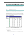
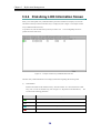
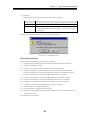
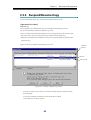
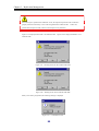
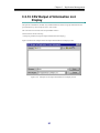
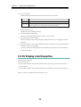
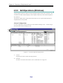
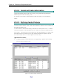
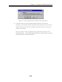
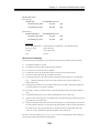
33..22..33 R
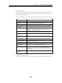
Reepplliiccaattiioonn IInnffoorrm
maattiioonn S
Sccrreeeenn
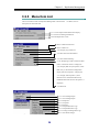
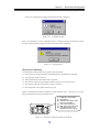
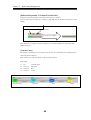
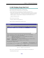
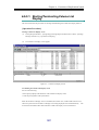
When click the [Replication Information] tab in the information list display area, the volume
information of the volumes in the selected disk array is displayed (refer to Figure 3-3 “Example of
Replication Information Screen”).
MV and RV are displayed in one line respectively (a total of two lines) for a pair and IV is displayed in
one line.
If pair setting is performed for volumes, the states of the volumes are displayed in two lines
for one pair so as to check the states of MV and RV.
IV is displayed in one line. To perform sort,
click the item name by which you want to sort. You can drag&drop an item to permute the order of
the items.
When pair setting and unpairing are performed, volume information is updated according to the order of
the last sort.
Figure 3-3
Example of Replication Information Screen
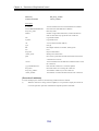
The Replication Information screen displays information regarding the following items.
30
Chapter 3 Replication Management
(i)
Classification
The volume types (volume attributes) are displayed.
Displayed Icon
Description
(Green)
MV.
Indicates Master Volume which is the volume of replication origin.
(Light Blue)
RV.
Indicates Replication Volume which is the volume of replication target.
(White)
IV. Indicates Isolated Volume and is the volume except the replication object.
IV becomes MV or RV by operating pair setting.
Indicates the volume on which a copy fault occurs.
When the snapshot function is used, the base-volume (BV) used by snapshot is also displayed.
For snapshot, refer to the “Snapshot User’s Manual (Function Guide)”.
Displayed Icon
(ii)
Description
(Green)
MV (MV/BV) having the BV attribute. Indicates the volume of replication
origin.
(White)
IV (BV) having the BV attribute. Indicates a volume which is not a replication
object. BV becomes MV (MV/BV) by operating pair setting.
Number
The logical disk number is displayed in hex digit.
It is the same as the logical disk number shown in the main screen (State Monitoring screen).
(iii) OS Type
Indicates the volume format.
When performing Replication operations, the OS type must be correctly specified.
Display
Description
A2
Indicates ACOS-2 format volume
A4
Indicates ACOS-4 format volume
AX
Indicates AIX format volume
CX
Indicates Solaris format volume
LX
Indicates Linux format volume
NX
Indicates HP-UX format volume
WN
Indicates Windows format volume
31
Chapter 3 Replication Management
(iv) Logical Disk Name
The identification name or identifier (see Note
) given for the logical disk is displayed.
It is the same as the logical disk name displayed in the main screen (State Monitoring screen) and
can be changed from the main screen (State Monitoring screen).
When the events given below have occurred when displaying the Replication Information screen, the
“Logical Disk Name” or “Paired Disk Name” field may show the unique volume number (Volume
Absolute Address) managed inside the disk array.
• The link failure has occurred.
• The Disk Array on the remote side is not managed by iSM or is in monitoring-stop state.
These events occur in a pair connected by RemoteDataReplication when the host to which a local
volume is connected cannot recognize the volume on the remote side.
Also in such a case,
operations such as Forced Separate and Forced Unpair for local volumes are enabled.
(v)
Pair Number
The logical disk number of paired volume is displayed in hex digit.
(vi) Pair Disk Name
The logical disk name of paired volume is displayed.
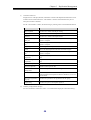
(vii) Activity State
The replication operation status is displayed.
Display
Description
Replicate
Indicates the status that copy is executing from MV to RV.
Separate
Indicates the disconnection status of MV to RV.
Restore
Indicates the status that copy is executing from RV to MV.
Restore (protect)
Indicates the state in which data is being copied from the RV into MV but the
updated data of the MV is not reflected into the RV.
32
Chapter 3 Replication Management
(viii) Disk Array
The identification name given to the Disk Array including the volume indicated by “Pair Number”
is displayed.
It is the same as the Disk Array Name displayed in the main screen (State Monitoring screen), and
can be changed from the main screen (State Monitoring screen).
If the Replication does not recognize the link destination of the disk array when the link is
established between disk arrays, the disk array name may be displayed as the address value
(Subsystem Absolute Address), which can uniquely identify the disk array not duplicated with other
disk arrays.
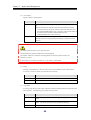
(ix) Sync State
The transition status in activity state is displayed.
For more information, refer to 2.3 “Replication Operations and State Transitions”.
Display
Description
Separating
Indicates the temporary status that difference between MV and RV is reducing to
zero during Separation Execution.
Separated
Indicates the status that the data copying is not processing between MV and RV.
It becomes this status right after pair setting.
Forced Separation Indicates the status that MV and RV are separated forcibly by the forced separate
instruction.
Fault
Indicates the status of forced separation inside the disk array due to copy fault
occurrence.
Sync Execution
Indicates the status that difference exists while copy is executing.
Synchronized
Indicates the status that reflection of the difference between the MV and RV at
the copy start instruction has been completed. Updates to the MV are reflected on
the RV sequentially for the pair in this state.
Restoring
Indicates the status that difference between MV and RV is not reflected at the
time of restore execution.
Restored
(synchronized)
Indicates the status that difference between MV and RV is reflected at the time of
restore execution. Updated MV content is reflected to RV.
33
Chapter 3 Replication Management
(x)
Copy Control State
The control status in copying is displayed.
For more information, refer to 2.4 “Copy Control State”.
Display
Description
Foreground Copy Indicates the copy state in the synchronous or semi-synchronous mode.
Background Copy Indicates the asynchronous copy state by difference management.
Freeze
Indicates that the data replication function is frozen.
Suspend
Indicates that copy operation is suspended.
Abnormal Suspend Indicates that copy is forcibly suspended in the disk array due to a copy fault.
(xi) Copy Mode
The copy control state in the synchronous state during Replicate/Restore is displayed.
Display
Synchronous
Description
This mode completes copying to RV within the processing time of the command
for writing to MV.
Semi-synchronous This mode stops the command for writing to MV and immediately performs
copying to RV.
Background Copy This mode performs copying to RV asynchronously after stopping the command
for writing to MV.
(xii) RV Mode
RV access restrictions are displayed.
For more information, refer to 2.6 “RV Access
Restriction”.
Display
Description
R/W Permit
Indicates that the volume can be read and written from the host.
Read Only
Indicates that the volume can be only read from the host.
Not Ready
Indicates that the volume cannot be operated from the host.
Not Available
Indicates that the volume cannot be operated from any host.
(xiii) Differential Quantity of Volume
Indicates the amount of difference after Separate (including the state right after pair setting) and
the amount of difference (the remaining amount) during synchronous execution.
Amount of difference may not change if I/O load is too heavy.
If a link failure occurs, amount of difference may not change.
In this case, refer to 2.2.2 (2)
“Link fault” in the “Data Replication User’s Manual (Installation and Operation Guide for
Windows)”.
34
Chapter 3 Replication Management
(xiv) Number of Pairs
Indicates the number of related pairs.
This value is equal to “the number of volumes which make
up the pair link” minus 1.
An example of pair relations and Number of Pairs is shown below.
Number of Pairs
Pair Relation
1
2
2
Some replication operations cannot be carried out while in the Replicate state, Restore state, or
Separate execution if the pair relation has multiple layers or if multiple RVs are connected to one
MV (Refer to the execution conditions of the operations).
If the Number of Pairs is 2 or greater,
check the hierarchy in the Connection screen.
(xv) Capacity [GB]
Indicates the capacity of the logical disk.
(xvi) LD Set Name
Indicates the name of the LD Set to which the volume belongs.
(xvii) ATgroup Name
Indicates the name of the AT-group to which the volume belongs.
* For details on the AT-group, refer to the “Data Replication User’s Manual (Disaster Recovery
System Installation and Operation Guide)”.
35
Chapter 3 Replication Management
33..22..44 D
Diisskk A
Arrrraayy LLIIN
NK
K IInnffoorrm
maattiioonn S
Sccrreeeenn
When you click the [Disk Array LINK Information] tab in the information list display area, the link
information currently set between the disk arrays is displayed (refer to Figure 3-4 “Example of Disk
Array LINK Information Screen”).
To perform sort, click the item name by which you want to sort. You can drag&drop an item to
permute the order of the items.
Figure 3-4
Example of Disk Array LINK Information Screen
The Disk Array LINK Information screen displays information regarding the following items.
(i)
LINK Number
Indicates the number of the linked disk arrays. The link number "0" is allocated to the first disk
array, and "1" to the second disk array (refer to Figure 3-5 “Replication Link Information”). The
icon shows the following path status.
Icon
Description
(Green)
Indicates the status of normal or link checking.
(Gray)
Indicates the offline status.
(Light Blue)
Indicates the status that the data replication function is frozen.
(Red)
Indicates that a fault occurs.
36
Chapter 3 Replication Management
(ii)
LINK Disk Array Name
Indicates the identification name assigned to the linked disk array.
(iii) Path Number
Indicates the connection path number in the link.
If the link is connected via four paths, the path numbers are 0, 1, 2, and 3, respectively (refer to
Figure 3-5 “Replication Link Information”).
(iv) Path State
Display
Description
Normal
Indicates the normal status.
Offline
Indicates that the link setting is unconfirmed during startup of the disk array.
Freeze
Indicates that the Data Replication function in the target disk array is frozen.
Link Checking
Indicates that the link status is being checked due to a failure of communication
in the link. It transits to Normal or Fault after a certain time interval.
Fault
Indicates that the link is invalid due to a failure of communication in the link.
(v)
Director Number
Indicates the replication director number (host director for the S2400 and 2800 series) that the link
is set.
37
Chapter 3 Replication Management
Figure 3-5 shows an example of two disk arrays connected to Disk Array 1 for using RDR.
The
following shows an example of 3000/4000 series.
Director Number
Port Number
Path Number
LINK Number
#00h
Path #00h
#0
#05h
#1
Path #01h
Path #02h
#0
#0dh
#1
Path #03h
Path #00h
Disk Array 2
#0
#11h
#1
Path #01h
Disk Array 1
#01h
Replication Director
Disk Array 3
Figure 3-5
Replication Link Information
38
Chapter 3 Replication Management
33..22..55 M
Meennuu IItteem
m LLiisstt
The list of menu bar items of Replication Management is shown below.
For details, refer to
description on each menu item.
3.3.13 “CSV Output of Information List Display”
3.3.14 “Save Pair Setting Information”
Closes the Replication screen.
Shows or hides the status bar.
Shows or hides IVs.
3.4.8 “Display Copy Fault List”
3.4.5 “Record Screen Information”
3.4.3 “Environment Setting”
3.3.12 “Displaying Volume Connection State”
(when “Connection Screen” is displayed)
3.4.6 “Display Disk Array Properties” (when
Disk Array is selected from configuration
display area and “Properties” is displayed)
3.4.7 “Display Link Properties” (when
Director Port is selected from Disk Array
LINK Information Screen and “Properties” is
displayed)
3.4.4 “Refresh”
3.3.1 “Pair Setting/Unpair”
3.3.1 “Pair Setting/Unpair”
3.3.2 “Replicate”
3.3.3 “Separate”
3.3.4 “Restore”
3.3.5 “Suspend/Resume Copy”
3.3.5 “Suspend/Resume Copy”
3.3.6 “Change to Background Copy”
3.3.7 “RV Mode Change”
39
Chapter 3 Replication Management
3.3.8 “Forced Separate”
3.3.9 “Forced Unpair”
3.3.10 “Freeze/Defreeze”
3.3.11 “Background Copy Level Change”
For details on operations related to the
AT-group, refer to the “Data Replication
User’s Manual (Disaster Recovery
System Installation and Operation
Guide)”.
Displays Help on the Replication screen.
Displays Help on the dialog list
regarding Replication screen.
40
Chapter 3 Replication Management
33..22..66 IInnffoorrm
maattiioonn D
Diissppllaayyeedd oonn E
Exxeeccuuttiioonn
D
Diiaalloogg
The Execution dialog displayed for replication operations can be switched to [Summary] or [Details]
display mode for the volume-related information displayed.
In the description given below, the unpair execution dialog is used as an example.
You can read
“operation” in the description as “Replicate”, “Restore”, etc. to be carried out.
Figure 3-6 shows an example of an Execution dialog information screen.
Items added when [Details] is selected
Figure 3-6
Example of Execution Dialog Information Screen
Information on the following items is displayed on the information screen of the execution dialog.
* Items (v), (vi), and (vii) are displayed only when [Details] is selected.
(i)
Execution Result
Displays the execution result of the operation. Operation cannot be performed for a pair with
“Unexecutable”.
After the operation is executed, the execution results for the operation are displayed.
To check
on the progress after the operation, close the execution dialog and check the progress on the
Connection Screen.
(ii)
Unexecutable Information
Displays the reason why operation cannot be performed.
(iii) Activity State
Displays the execution state of the pair.
41
Chapter 3 Replication Management
(iv) Logical Disk Name
Displays the logical disk name of MV.
(v)
Copy Control State
Displays the control state during copy.
(vi) Sync State
Displays the transition status in the activity state.
(vii) Copy Mode
Displays the Synchronous/Semi-synchronous mode during copy operation.
(viii) Number
Displays the logical disk number of MV.
(ix) MV Disk Array Name
Displays the disk array name to which MV belongs.
(x)
Pair Disk Name
Displays the logical disk name of RV.
(xi) Pair Number
Displays the logical disk number of RV.
(xii) RV Disk Array Name
Displays the disk array name to which RV belongs.
(xiii) ATgroup Name
Displays the name of the AT-group to which the volume belongs.
42
Chapter 3 Replication Management
33..33 V
Vaarriio
ou
uss O
Op
peerraattiio
on
nss o
off R
Reep
plliiccaattiio
on
n
M
Maan
naag
geem
meen
ntt
33..33..11 P
Paaiirr S
Seettttiinngg//U
Unnppaaiirr
To perform replication operations, you must set pairs beforehand.
To set a pair, set the original volume as MV and the target volume as RV.
You can also use the
volume you have set as RV in another pair by setting it as MV.
You can set pairs freely within the following bounds.
• You can set up to three volumes of RVs (dRVs) or up to four volumes of RVs (including rRV) for
one MV at the same time.
• You can set RVs in up to 2 disk arrays for one PV.
• You can set DynamicDataReplication only for one layer in the disk array.
• You can set a pair only when the two volumes have the same capacity.
Figure 3-7 shows an example of the pair setting.
PV
RV
MV
PV
MV
RV
MV
RV
RV
Figure 3-7
Example of Pair Setting
You may want to specify multiple pairs simultaneously, for example, when you initially build or rebuild
a replication environment.
To specify pair environments at a time, use “Replication Setting” of “New
Setting” which is one of the configuration setting functions.
For details, refer to the “Configuration
Setting Tool User’s Manual (GUI)” and 3.4.2 “Save Pair Setting Information”.
43
Chapter 3 Replication Management
[Operation Procedure]
Pair Setting
Do one of the following to display the Pair Setting screen.
y Select a volume in the Replication Information screen, click [Operation] on the menu bar of the
Replication screen, and then select [Pair Setting].
y Right-click in the Replication Information screen, and then select [Pair Setting].
In pair setting, whether the selected volume can be set as MV is determined automatically. If the
selected volume is a volume for which pair setting cannot be performed as MV, the following prompt
appears.
Figure 3-8
Confirmation Screen
The possible causes are as follows:
Unexecutable condition
Description
DDR/RDR
Due to the description of the reason, the volume cannot be set as MV of
DDR and RDR.
DDR
Due to the description of the reason, the volume cannot be set as MV of
DDR.
RDR
Due to the description of the reason, the volume cannot be set as MV of
RDR.
After checking the message, click the [Yes] button to display the Pair Setting screen.
volume again on the Replication Information screen, click the [No] button.
44
To select a
Chapter 3 Replication Management
Figure 3-9 shows an example of the Pair Setting Screen.
(i)
(ii)
(iii)
(iv)
(v)
Figure 3-9
Example of Pair Setting Screen
After the Pair Setting, the copy operation such as Replicate, Restore etc. is available.
(i) Data Replication Mode
Select the method of setting pairs.
Radio Button
Description
Dynamic Data Replication (within a Disk MV and RV use the volumes in the same Disk
Array)
Array.
Remote Data Replication (between Disk
Arrays)
MV and RV use the volumes in different Disk
Arrays.
(ii) Disk Array Name
On the MV part, displays the disk array name with the selected volume.
On the RV part, displays the disk array name for which pair setting of remote data replication
can be performed.
(iii) Object
To make only the selected volume the object of MV, check this (default).
To make all the volumes that can be used as MV the objects, uncheck this.
(iv) LD Set Name
You can narrow down object volumes for which pair setting can be performed by the LD Set
Name.
When the object volume for which pair setting can be performed is not registered in the LD
Set, LD Set Name cannot be used for narrowing down nor selected.
45
Chapter 3 Replication Management
ALL
:
All volumes become selectable objects.
LD Set Name :
Volumes registered in the selected LD Set become selectable objects.
Undefined
Volumes not registered in the LD Set become selectable objects.
:
(v) Logical Disk
Select the Logical Disk which you want to set.
When you click the [Execute] button, the following message is displayed.
Figure 3-10
Confirmation Screen
Unpair
Do one of the following to display the Unpair screen.
y Select a volume in the Replication Information screen, click [Operation] on the menu bar of the
Replication screen, and then select [Unpair].
y Right-click in the Replication Information screen, and then select [Unpair].
Figure 3-11 shows an example of the Unpair screen.
Selected
Not selected
Cannot be
selected
(i)
(ii)
Figure 3-11
Example of Unpair Screen
46
Chapter 3 Replication Management
From the list, select a pair you want to unpair, and then click the [Execute] button.
You can select multiple executable pairs and execute them in a batch.
Unexecutable pairs cannot be selected.
(i)
Selected Volume List
Displays the list of the pair (MV/RV) information selected in the Replication Information screen.
Volumes whose Execution Result is “Unexecutable” cannot be selected because they do not
satisfy the execution conditions.
For the “Unexecutable” volumes, do the following by referring to the Unexecutable Information.
Unexecutable Information
Measure
Have Unpaired
Execute it for a volume with the pair setting.
Replicated
Change it to the Separated state and execute it again.
Restored
Change it to the Separated state and execute it again.
Separating
Execute it again in the Separated state.
Freeze
Defreeze the Data Replication function and execute it again.
MV Force Unpaired
Perform Forced Unpair for RV.
MV Monitoring
Suspended
Change the disk array of MV to the Monitored state and execute it
again.
RV Monitoring
Suspended
Change the disk array of RV to the Monitored state and execute it
again.
RV Force Unpaired
Perform Forced Unpair for MV.
MV Outside iSM
Management
Execute it for a pair under the iSM management.
All Link Path Abnormal Refer to 2.2.2 (2) “Link fault” in the “Data Replication User’s
Manual (Installation and Operation Guide for Windows)” to recover
from the failure.
Have been registered to Execute it for a pair that is not registered in the AT-group.
ATgroup
Or, execute it after deleting a volume from the AT-group.
(ii)
Summary Display/Details Display
For more information on this item, refer to 3.2.6 “Information Displayed on Execution Dialog”.
When you click the [Execute] button, the following message is displayed.
Figure 3-12
47
Confirmation Screen
Chapter 3 Replication Management
[Execution Conditions]
To Pair setting or Unpair, the following conditions must be satisfied.
Conditions for Pair setting
Volumes in which the pair setting is performed must satisfy the following conditions.
(i)
The volume capacities of MV and RV match.
(ii)
The specified RV is not set as RV for another pair.
(iii) If the specified MV is set as MV for another pair, the maximum number of simultaneous pairs is
not exceeded.
(iv)
The volume formats match.
(v)
The pair hierarchy does not form any loop.
(vi)
When MV and RV exist in the same disk array and if RV is used to set another pair, a volume in
another disk array is specified.
(vii) The disk array where the specified MV and RV are stored is monitored.
(viii) The disk array where the specified MV and RV are stored is not in the Freeze state.
(ix)
If the specified MV is registered in the AT-group, the MV and the specified RV are set as a DDR
pair.
(x)
A volume having snapshot attributes other than BV is not set as MV.
(xi)
A volume having snapshot attributes is not set as RV.
Do not execute Pair Setting for a reserved volume of the business server or for a volume specified as
a performance optimization work disk.
The replication screen does not display the Volume List.
Conditions for Unpair
Volumes for unpair must satisfy the following conditions.
(i)
The specified MV and RV are paired.
(ii)
The specified MV and RV are in the Separated state.
(iii) The disk array where the specified MV and RV are stored is monitored.
(iv)
The disk array where the specified MV and RV are stored is not in the Freeze state.
(v)
The specified MV is not registered in the AT-group.
48
Chapter 3 Replication Management
RV unmounted by the ReplicationControl function from a business server or backup server of
Windows may be set in the Not Ready state.
In this case, even if the synchronous state of the pair
is “separated”, the RV mode is kept in the Not Ready state.
Make sure to change the RV set in the Not Ready state to the R/W Permit state by “RV mode
change” operation prior to unpair with the exception of the case where the logical disk of RV is used
by a business server or backup server in succession after unpair.
49
Chapter 3 Replication Management
33..33..22 R
Reepplliiccaattee
When you perform Replicate for volumes with the pair setting, copy from MV to RV starts.
[Operation Procedure]
Do one of the following to display the Replicate screen.
• Select a volume in the Replication Information screen, click [Operation] on the menu bar of the
Replication screen, point to [Volume Operation], and then select [Replicate].
• Right-click in the Replication Information screen, point to [Volume Operation], and then select
[Replicate].
Figure 3-13 shows an example of the Replicate screen.
Cannot be
selected
Selected
(i)
Not selected
(ii)
(iii)
(iv)
(v)
Figure 3-13
Example of Replicate Screen
From the list, select a pair for which you want to perform the operation, and then click the [Execute]
button.
You can select multiple executable pairs and execute them in a batch.
Unexecutable pairs cannot be selected.
(i)
Selected Volume List
Displays the list of the pair (MV/RV) information selected in the Replication Information screen.
Volumes whose Execution Result is “Unexecutable” cannot be selected because they do not
satisfy the execution conditions.
50
Chapter 3 Replication Management
For the “Unexecutable” volumes, do the following by referring to the Unexecutable Information.
Unexecutable Information
Measure
Have Unpaired
Execute it for a volume with the pair setting.
Replicated
Execute it for a volume in the Separate state.
Restored
Execute it for a volume in the Separate state.
Being replicated by
other pair
Replicate is being executed in another layer.
Separate is complete.
Being restored by other Restore is being executed in another layer.
pair
Separate is complete.
Freeze
Execute it again after
Execute it again after
Defreeze the Data Replication function and execute it again.
Being separated by other Separate is being executed in another layer. Execute it again after
pair
Separate is complete.
MV Monitoring
Suspended
Change the disk array of MV to the Monitored state and execute it
again.
RV Monitoring
Suspended
Change the disk array of RV to the Monitored state and execute it
again.
MV Force Unpaired
Perform Forced Unpair for RV.
RV Force Unpaired
Perform Forced Unpair for MV.
MV Outside iSM
Management
Execute it for a pair under the iSM management.
All Link Path Abnormal Refer to 2.2.2 (2) “Link fault” in the “Data Replication User’s
Manual (Installation and Operation Guide for Windows)” to recover
from the failure.
Have been registered to Execute it for a pair that is not registered in the AT-group.
ATgroup
Snapshotting
(ii)
Execute it for a pair that is not operating snapshot.
Summary Display/Details Display
For more information on this item, refer to 3.2.6 “Information Displayed on Execution Dialog”.
(iii) Range
Normally, Only Difference is selected, which copies only the difference area of MV and RV.
You can also select All, which copies the entire area explicitly.
Radio Button
Description
Only Difference
Copies only the difference of the volumes.
All
Copies the entire volume.
51
Chapter 3 Replication Management
(iv)
Copy Mode
You can specify the copy control state in Replicate Execution and the Synchronous state at the
same time as Replicate.
The following copy modes can be specified.
Radio Button
(v)
Description
Synchronous
Changes the copy control state to the foreground copy
(Synchronous) mode.
Semi-synchronous
Changes the copy control state to the foreground copy
(Semi-synchronous) mode. This can be specified for pairs
in different disk arrays.
Background Copy
Changes the copy control state to the Background Copy
state.
RV Status
Specifies the access restrictions from the host until Replicate is complete.
Radio Button
Description
Not Ready
Operations for the volume cannot be performed from the host.
Read Only
For the volume, only read can be performed from the host.
* Care should be taken to specify Read Only.
Refer to 2.6 “RV Access Restriction”.
When you click the [Execute] button, the following message is displayed.
Figure 3-14
Confirmation Screen
[Execution Conditions]
To perform Replicate, the following conditions must be satisfied.
(i)
The target MV is recognized by Replication Management as the Replication target disk.
(ii)
The target MV and RV are paired.
(iii) The activity state of the target pair is Separate.
(iv)
The Semi-synchronous Copy mode cannot be specified for pairs set in the same disk array.
The Semi-synchronous Copy mode can be specified only for pairs set in different disk arrays.
(v)
The pair of the specified MV and the paired RV pair are not in the Restore state.
52
Chapter 3 Replication Management
(vi)
The activity state of the pair of the specified MV and the paired upper MV is not in the Restore
state.
(vii) The activity state of the pair of the specified RV and the paired lower RV is not in the Restore
state.
(viii) The disk array where the specified MV and RV are stored is not Freeze state.
(ix)
The disk array where the specified MV and RV are stored is monitored.
(x)
The RV has been unmounted from the host.
(xi)
The specified MV is not registered in the AT-group.
(xii) Separate is not being performed between the upper volume and the lower volume that are paired.
(xiii) Snapshot is not in operation.
Figure 3-15 illustrates the execution conditions of Replicate.
(Each of (i) to (xiii) in the figure
corresponds to the respective number above.)
(i)
(ii)
(iii)
(iv)
(vi) Not in the Restore state
(xii) Separate is not being
performed between the
upper volume and the
lower volume that are
paired.
MV
Target Pair
RV
MV
RV
MV
Target Pair
MV
RV
RV
Replication Target Disk
Pair Setting
Separated
Semi-synchronous not
allowed for the same disk
array
(viii) Not in the Freeze state
(ix) Disk array monitored
(x) RV is unmounted from the
host.
(xi) The specified MV is not
registered in the AT-group.
(vii) Not in the Restore state
(xii) Separate is not being
performed between the
upper volume and the lower
volume that are paired.
RV
(v) Not in the Restore state
Target Pair
MV
BV
(xiii) Snapshot is not in operation.
RV
SV
Figure 3-15
Execution Conditions of Replicate
53
Chapter 3 Replication Management
33..33..33 S
Seeppaarraattee
If Separate is performed for paired volumes, MV is separated from RV and RV is made available. RV
cannot be reused until Separate is completed.
However, it can be used for Separate(immediate).
[Operation Procedure]
Do one of the following to display the Separate screen.
• Select a volume in the Replication Information screen, click [Operation] on the menu bar of the
Replication screen, point to [Volume Operation], and then select [Separate].
• Right-click in the Replication Information screen, point to [Volume Operation], and then select
[Separate].
Figure 3-16 shows an example of the Separate screen.
Selected
Cannot be
selected
Not selected
(i)
(ii)
(iii)
(iv)
Figure 3-16
Example of Separate Screen
From the list, select a pair for which you want to perform the operation, and then click the [Execute]
button.
You can select multiple executable pairs and execute them in a batch.
Unexecutable pairs cannot be selected.
54
Chapter 3 Replication Management
(i)
Selected Volume List
Displays the list of the pair (MV/RV) information selected in the Replication Information screen.
Volumes whose Execution Result is “Unexecutable” cannot be selected because they do not
satisfy the execution conditions.
For the “Unexecutable” volumes, do the following by referring to the Unexecutable Information.
Unexecutable Information
(ii)
Measure
Have Unpaired
Execute it for a volume with a volume of the Synchronous state.
Separated
Execute it for a volume in the Synchronous state.
Restoring
Execute it again when Restored is completed.
Suspend State
Execute it again in the Synchronous state after copy is resumed.
Abnormal Suspend
Refer to 2.2.2 “HW Fault Unique to Replication” in the “Data
Replication User’s Manual (Installation and Operation Guide for
Windows)” to recover from the failure.
Freeze
Defreeze the Data Replication function and execute it again.
MV Monitoring
Suspended
Change the disk array of MV to the Monitored state and execute it
again.
RV Monitoring
Suspended
Change the disk array of RV to the Monitored state and execute it
again.
MV Force Unpaired
Perform Forced Unpair for RV.
RV Force Unpaired
Perform Forced Unpair for MV.
RV Forced Separate
Execute it for a volume in the Synchronous state.
MV Outside iSM
Management
Execute it for a pair under the iSM management.
All Link Path Abnormal
Refer to 2.2.2 (2) “Link fault” in the “Data Replication User’s
Manual (Installation and Operation Guide for Windows)” to recover
from the failure.
Have been registered to
ATgroup
Execute it for a pair that is not registered in the AT-group.
Summary Display/Details Display
For more information on this item, refer to 3.2.6 “Information Displayed on Execution Dialog”.
55
Chapter 3 Replication Management
(iii) RV Use Start Time
Determine when to make the RV available.
Radio Button
Description
Separate End
After Separate execution, the RV becomes available when the difference
between the MV and RV contents has been reflected into the RV
(Separate(completion)).
Separate Start
After Separate execution, the RV is immediately available while the
difference between the MV and RV contents is being reflected into the RV
(Separate(immediate)).
* DynamicDataReplication Ver2 needs to be installed for using this function.
The function is
available only for paired volumes in the same disk array.
(iv)
Separated RV Status
Specifies the operation in response to a write request from the host after Separate is complete.
Radio Button
Description
R/W Permit
Read and write can be performed for a separated RV is complete from the
host.
Read Only
Only read can be performed for a separated RV is complete from the host.
When you click the [Execute] button, the following message is displayed.
Figure 3-17
Confirmation Screen
[Execution Conditions]
To perform Separate, the following conditions must be satisfied. RV cannot be reused until Separate
is completed. However, it can be used for Separate(completion).
(i)
The target MV is recognized by Replication Management as the Replication target disk.
(ii)
The target MV and RV are paired.
(iii) The target pair is not in the Restore Execution state.
(iv)
The disk array where the specified MV and RV are stored is not in the Freeze state.
(v)
The disk array where the specified MV and RV are stored is monitored.
(vi)
The MV is unmounted from the host.
(vii) The specified MV is not registered in the AT-group.
(viii) Separate is not being performed between the upper volume and the lower volume that are paired.
56
Chapter 3 Replication Management
Figure 3-18 illustrates the execution conditions of Separate.
(Each of (i) to (viii) in the figure
corresponds to the respective number above.)
(i)
(ii)
(iii)
(iv)
(v)
(vi)
(vii)
Replication Target Disk
Pair Setting
Not in Restore execution
Not in the Freeze state
Disk array monitored
MV is unmounted from the host.
The specified MV is not registered in the
AT-group.
(viii) Separate is not being performed
between the upper volume and the lower
volume that are paired.
Target Pair
MV
RV
Figure 3-18
Execution Conditions of Separate
57
Chapter 3 Replication Management
33..33..44 R
Reessttoorree
When you perform Restore for volumes with the pair setting, copy from RV to MV starts.
[Operation Procedure]
Do one of the following to display the Restore screen.
• Select a volume in the Replication Information screen, click [Operation] on the menu bar of the
Replication screen, point to [Volume Operation], and then select [Restore].
• Right-click in the Replication Information screen, point to [Volume Operation], and then select
[Restore].
Figure 3-19 shows an example of the Restore screen.
Selected
Not selected
(i)
Cannot be
selected
(ii)
(iii)
(iv)
(v)
(vi)
Figure 3-19
Example of Restore Screen
From the list, select a pair for which you want to perform the operation, and then click the [Execute]
button.
You can select multiple executable pairs and execute them in a batch.
Unexecutable pairs cannot be selected.
58
Chapter 3 Replication Management
(i)
Selected Volume List
Displays the list of the pair (MV/RV) information selected in the Replication Information screen.
Volumes whose Execution Result is “Unexecutable” cannot be selected because they do not
satisfy the execution conditions.
For the “Unexecutable” volumes, do the following by referring to the Unexecutable Information.
Unexecutable Information
Measure
Have Unpaired
Execute it for a volume with the pair setting.
Replicated
Execute it for a volume in the Separate state.
Restored
Execute it for a volume in the Separate state.
Being replicated by
other pair
Replicate is being executed in another layer.
Separate is complete.
Being restored by other Restore is being executed in another layer.
pair
Separate is complete.
Execute it again after
Execute it again after
Separating
Execute it again in the Separated state.
Freeze
Defreeze the Data Replication function and execute it again.
Being separated by other Separate is being executed in another layer. Execute it again after
pair
Separate is complete.
MV Monitoring
Suspended
Change the disk array of MV to the Monitored state and execute it
again.
RV Monitoring
Suspended
Change the disk array of RV to the Monitored state and execute it
again.
MV Force Unpaired
Perform Forced Unpair for RV.
RV Force Unpaired
Perform Forced Unpair for MV.
MV Outside iSM
Management
Execute it for a pair under the iSM management.
All Link Path Abnormal Refer to 2.2.2 (2) “Link fault” in the “Data Replication User’s
Manual (Installation and Operation Guide for Windows)” to recover
from the failure.
Have been registered to Execute it for a pair that is not registered in the AT-group.
ATgroup
Snapshotting
(ii)
Execute it for a pair not in snapshot operation.
Summary Display/Details Display
For more information on this item, refer to 3.2.6 “Information Displayed on Execution Dialog”.
59
Chapter 3 Replication Management
(iii) Active Mode
Specify a Restore operation mode.
Radio Button
RV Protection
Description
Performs restoration without reflecting the updated data of the MV into the
RV.
When the restoration is completed, Separate is automatically executed.
* To use this function for paired volumes located in the same disk array,
the DynamicDataReplication Ver2 is necessary, and to use this function
for paired volumes located in different disk arrays, the
RemoteDataReplication Ver2 is necessary.
RV Update
Performs restoration while reflecting the updated data of the MV into the RV.
When the restoration is completed, the state changes to Synchronous State
(rst/sync).
The default operation mode in (iii) is “RV Protection”.
Confirm the Restore operation mode before executing Restore.
“RV Update” needs to be selected for executing Restore in the same operation mode as for
Version1.4 or earlier.
If “RV Protection” is selected, selection of (v) Copy mode is not permitted.
(iv)
Range
Normally, Only Difference is selected, which copies only the difference area of MV and RV.
You can also select All, which copies the entire area explicitly.
Radio Button
(v)
Description
Only Difference
Copies only the difference of the volumes.
All
Copies the entire volume.
Copy Mode
You can specify the copy control state in Restore Execution and the Synchronous state at the same
time as Restore. The following copy modes can be specified.
Radio Button
Synchronous
Description
Changes the copy control state to the foreground copy (Synchronous)
mode.
Semi-synchronous Changes the copy control state to the foreground copy (Semi-synchronous)
mode. This can be specified for pairs in different disk arrays.
Background Copy Changes the copy control state to the Background Copy state.
60
Chapter 3 Replication Management
(vi)
RV Status
Specifies the access restrictions from the host until Restore is complete.
Radio Button
Description
Not Ready
Operations for the volume cannot be performed from the host.
Read Only
For the volume, only read can be performed from the host.
* Care should be taken to specify Read Only.
Restriction”.
Refer to 2.6 “RV Access
When you click the [Execute] button, the following message is displayed.
Figure 3-20
Confirmation Screen
[Execution Conditions]
To perform Restore, the following conditions must be satisfied.
(i)
The target MV is recognized by Replication Management as the Replication target disk.
(ii)
The target MV and RV are paired.
(iii) The activity state of the target pair is Separate, but not Separate Execution.
(iv) The Semi-synchronous Copy mode cannot be specified for pairs set in the same disk array.
The Semi-synchronous Copy mode can be specified only for pairs set in different disk arrays.
(v)
The activity state of the pair of the specified MV and the paired RV is Separate.
(vi) The activity state of the pair of the specified MV and the paired upper MV is Separate.
(vii) The activity state of the pair of the specified RV and the paired lower RV is Separate.
(viii) The disk array where the specified MV and RV are stored is not in the Freeze state.
(ix) The disk array where the specified MV and RV are stored is monitored.
(x)
The MV and RV are unmounted from the host.
(xi) The specified MV is not registered in the AT-group.
(xii) Separate is not being performed between the upper volume, the lower volume, and the derived
volume that are paired.
(xiii) Snapshot is not in operation.
61
Chapter 3 Replication Management
Figure 3-21 illustrates the execution conditions of Restore.
(Each of (i) to (xiii) in the figure
corresponds to the respective number above.)
Target Pair
RV
MV
Replication Target Disk
Pair Setting
Separated
Semi-synchronous not
allowed for the same disk
array
(viii) Not in the Freeze state
(ix) Disk array monitored
(x) MV and RV are
unmounted from the host.
(xi) The specified MV is not
registered in the
AT-group.
(i)
(ii)
(iii)
(iv)
(vi) Separated
(xii) Separate is not
being performed
for an upper
volume.
MV
RV
MV
(vii) Separated
(xii) Separate is not being
performed for a lower pair.
Target Pair
MV
RV
RV
(v) Separated
(xii) Separate is not being
performed for a derived
pair.
RV
Target Pair
MV
BV
(xiii) Snapshot is not in operation.
Figure 3-21
RV
SV
Execution Conditions of Restore
62
Chapter 3 Replication Management
33..33..55 S
Suussppeenndd//R
Reessuum
mee C
Cooppyy
You can suspend and resume copy operation in the Replicate or Restore state.
[Operation Procedure]
Suspend Copy
The Foreground Copy or Background Copy state is changed to the Suspend Copy state.
Do one of the following to display the Suspend Copy screen.
• Select a volume in the Replication Information screen, click [Operation] on the menu bar of the
Replication screen, point to [Volume Operation], and then select [Suspend Copy].
• Right-click in the Replication Information screen, point to [Volume Operation], and then select
[Suspend Copy].
Figure 3-22 shows an example of the Suspend Copy screen.
Cannot be
selected
(i)
Selected
Not selected
(ii)
Figure 3-22
Example of Suspend Copy Screen
From the list, select a pair for which you want to perform the operation, and then click the
[Execute] button.
You can select multiple executable pairs and execute them in a batch.
Unexecutable pairs cannot be selected.
63
Chapter 3 Replication Management
(i)
Selected Volume List
Displays the list of the pair (MV/RV) information selected in the Replication Information screen.
Volumes whose Execution Result is “Unexecutable” cannot be selected because they do not
satisfy the execution conditions.
For the “Unexecutable” volumes, do the following by referring to the Unexecutable Information.
Unexecutable Information
Measure
Have Unpaired
Execute it for a volume with the pair setting.
Already Suspended
Execute it for a volume in the Replicate state, Restore state.
Separate State
Execute it for a volume in the Replicate state or Restore state.
Freeze
Defreeze the Data Replication function and execute it again.
MV Monitoring
Suspended
Change the disk array of MV to the Monitored state and execute it
again.
MV Force Unpaired
Perform Forced Unpair for RV.
RV Force Unpaired
Perform Forced Unpair for MV.
RV Forced Separate
Execute it for a volume in the Synchronous state.
MV Outside iSM
Management
Execute it for a pair under the iSM management.
All Link Path Abnormal Refer to 2.2.2 (2) “Link fault” in the “Data Replication User’s
Manual (Installation and Operation Guide for Windows)” to recover
from the failure.
Have been registered to Execute it for a pair that is not registered in the AT-group.
ATgroup
(ii)
Summary Display/Details Display
For more information on this item, refer to 3.2.6 “Information Displayed on Execution Dialog”.
Resume Copy
The Suspend Copy or Background Copy state is changed to the Foreground Copy state.
Do one of the following to display the Resume Copy screen.
• Select a volume in the Replication Information screen, click [Operation] on the menu bar of the
Replication screen, point to [Volume Operation], and then select [Resume Copy].
• Right-click in the Replication Information screen, point to [Volume Operation], and then select
[Resume Copy].
64
Chapter 3 Replication Management
Figure 3-23 shows an example of the Resume Copy screen.
Not
selected
Cannot be
selected
(i)
Selected
(ii)
(iii)
Figure 3-23
Example of Resume Copy Screen
From the list, select a pair for which you want to perform the operation, and then click the
[Execute] button.
You can select multiple executable pairs and execute them in a batch.
Unexecutable pairs cannot be selected.
(i)
Selected Volume List
Displays the list of the pair (MV/RV) information selected in the Replication Information screen.
Volumes whose Execution Result is “Unexecutable” cannot be selected because they do not
satisfy the execution conditions.
For the “Unexecutable” volumes, do the following by referring to the Unexecutable Information.
65
Chapter 3 Replication Management
Unexecutable Information
Measure
Have Unpaired
Execute it for a volume with the pair setting.
Foreground Copy State
Execute it for a volume in the Suspend state.
Separate State
Execute it for a volume in the Suspend state.
Freeze
Defreeze the Data Replication function and execute it again.
MV Monitoring
Suspended
Change the disk array of MV to the Monitored state and execute it
again.
RV Monitoring
Suspended
Change the disk array of RV to the Monitored state and execute it
again.
MV Force Unpaired
Perform Forced Unpair for RV.
RV Force Unpaired
Perform Forced Unpair for MV.
RV Forced Separate
Execute it for a volume in the Synchronous state.
MV Outside iSM
Management
Execute it for a pair under the iSM management.
All Link Path Abnormal Refer to 2.2.2 (2) “Link fault” in the “Data Replication User’s
Manual (Installation and Operation Guide for Windows)” to recover
from the failure.
Have been registered to Execute it for a pair that is not registered in the AT-group.
ATgroup
(ii)
Summary Display/Details Display
For more information on this item, refer to 3.2.6 “Information Displayed on Execution Dialog”.
(iii) Copy Mode
You can specify the copy control state when copy is resumed.
The following copy modes can be specified.
Radio Button
Description
Synchronous
Changes the copy control state to the foreground copy (Synchronous)
mode.
Semi-synchronous
Changes the copy control state to the foreground copy
(Semi-synchronous) mode. This can be specified for pairs in
different disk arrays.
Background Copy
Changes the copy control state to the Background Copy state.
When you click the [Execute] button, the following message is displayed.
Figure 3-24
66
Confirmation Screen
Chapter 3 Replication Management
[Execution Conditions]
To perform operations of suspending/resuming copy, the following conditions must be satisfied.
(i)
The target MV is recognized by Replication Management as the Replication target disk.
(ii) The target MV and RV are paired.
(iii) The activity state of the target pair is Replicate or Restore.
(iv) The Semi-synchronous Copy mode cannot be specified for pairs set in the same disk array.
The Semi-synchronous Copy mode can be specified only for pairs set in different disk arrays. (Can
be set only when copy is resumed.)
(v) The disk array where the specified MV and RV are stored is not in the Freeze state.
(vi) The disk array where the specified MV and RV are stored is monitored.
(In case of copy suspend, MV must be monitored)
(vii) The specified MV is not registered in the AT-group.
Figure 3-25 illustrates the execution conditions of operations of suspending/resuming copy.
(Each of
(i) to (vii) in the figure corresponds to the respective number above.)
(i)
(ii)
(iii)
(iv)
Replication Target Disk
Pair Setting
Replicate or Restore
Semi-synchronous not allowed
for the same disk array
(v) Not in the Freeze state
(vi) Disk array monitored
(vii) The specified MV is not
registered in the AT-group.
Target Pair
MV
Figure 3-25
RV
Execution Conditions of Suspend Copy and Resume Copy State Operation
67
Chapter 3 Replication Management
33..33..66 C
Chhaannggee ttoo B
Baacckkggrroouunndd C
Cooppyy
The copy control state is changed from the Replicate or Restore state to the Background Copy state.
[Operation Procedure]
Do one of the following to display the Change to Background Copy screen.
• Select a volume in the Replication Information screen, click [Operation] on the menu bar of the
Replication screen, point to [Volume Operation], and then select [Change to Background Copy].
• Right-click in the Replication Information screen, point to [Volume Operation], and then select
[Change to Background Copy].
Figure 3-26 shows an example of the Change to Background Copy screen.
Not selected
(i)
Selected
Cannot be
selected
(ii)
Figure 3-26
Example of Change to Background Copy Screen
From the list, select a pair for which you want to perform the operation, and then click the [Execute]
button.
You can select multiple executable pairs and execute them in a batch.
Unexecutable pairs cannot be selected.
(i)
Selected Volume List
Displays the list of the pair (MV/RV) information selected in the Replication Information screen.
Volumes whose Execution Result is “Unexecutable” cannot be selected because they do not
satisfy the execution conditions.
For the “Unexecutable” volumes, do the following by referring to the Unexecutable Information.
68
Chapter 3 Replication Management
Unexecutable Information
Measure
Have Unpaired
Execute it for a volume with the pair setting.
Separate State
Execute it for a volume in the Replicate state or Restore state.
Already Background Copy Execute it for a volume in Foreground Copy.
State
Freeze
Defreeze the Data Replication function and execute it again.
MV Monitoring Suspended Change the disk array of MV to the Monitored state and execute it
again.
RV Monitoring Suspended Change the disk array of RV to the Monitored state and execute it
again.
MV Force Unpaired
Perform Forced Unpair for RV.
RV Force Unpaired
Perform Forced Unpair for MV.
RV Forced Separate
Execute it for a volume in the Synchronous state.
MV Outside iSM
Management
Execute it for a pair under the iSM management.
All Link Path Abnormal
Refer to 2.2.2 (2) “Link fault” in the “Data Replication User’s Manual
(Installation and Operation Guide for Windows)” to recover from the
failure.
Have been registered to
ATgroup
Execute it for a pair that is not registered in the AT-group.
(ii)
Summary Display/Details Display
For more information on this item, refer to 3.2.6 “Information Displayed on Execution Dialog”.
When you click the [Execute] button, the following message is displayed.
Figure 3-27
Confirmation Screen
[Execution Conditions]
To perform changes to Background Copy, the following conditions must be satisfied.
(i)
The target MV and RV are recognized by Replication Management as the Replication target disk.
(ii)
The target MV and RV are paired.
(iii) The activity state of the target pair is Replicate or Restore.
(iv)
The disk array where the specified MV and RV are stored is not in the Freeze state.
(v)
The disk array where the specified MV and RV are stored is monitored.
(vi)
The specified MV is not registered in the AT-group.
69
Chapter 3 Replication Management
Figure 3-28 illustrates the execution conditions of changes to Background Copy. (Each of (i) to (vi) in
the figure corresponds to the respective number above.)
(i)
(ii)
(iii)
(iv)
(v)
(vi)
Target Pair
MV
Figure 3-28
RV
Replication Target Disk
Pair Setting
Replicate or Restore
Not in the Freeze state
Disk array monitored
The specified MV is not
registered in the AT-group.
Execution Conditions of Change to Background Copy
70
Chapter 3 Replication Management
33..33..77 R
RV
VM
Mooddee C
Chhaannggee
You can change the RV access restriction.
[Operation Procedure]
Do one of the following to display the RV Mode Change screen.
• Select a volume in the Replication Information screen, click [Operation] on the menu bar of the
Replication screen, point to [Volume Operation], and then select [RV Mode Change].
• Right-click in the Replication Information screen, point to [Volume Operation], and then select [RV
Mode Change].
Figure 3-29 shows is an example of the RV Mode Change screen.
Not selected
(i)
Selected
(ii)
(iii)
Figure 3-29
Example of RV Mode Change Screen
From the list, select a pair for which you want to perform the operation, and then click the [Execute]
button.
You can select multiple executable pairs and execute them in a batch.
Unexecutable pairs cannot be selected.
71
Chapter 3 Replication Management
(i)
Selected Volume List
Displays the list of the pair (MV/RV) information selected in the Replication Information screen.
Volumes whose Execution Result is “Unexecutable” cannot be selected because they do not
satisfy the execution conditions.
For the “Unexecutable” volumes, do the following by referring to the Unexecutable Information.
Unexecutable Information
(ii)
Measure
Have Unpaired
Execute it for a volume with the pair setting.
Freeze
Defreeze the Data Replication function and execute it again.
RV Outside iSM
Management
Execute it for a pair under the iSM management.
RV Monitoring
Suspended
Change the disk array of RV to the Monitored state and execute it
again.
MV Force Unpaired
Perform Forced Unpair for RV.
RV Force Unpaired
Perform Forced Unpair for MV.
All Link Path Abnormal
Refer to 2.2.2 (2) “Link fault” in the “Data Replication User’s
Manual (Installation and Operation Guide for Windows)” to recover
from the failure.
Have been registered to
ATgroup
Execute it for a pair that is not registered in the AT-group.
Summary Display/Details Display
For more information on this item, refer to 3.2.6 “Information Displayed on Execution Dialog”.
(iii) RV Status
Specifies the operations for a write request from the host.
Radio Button
R/W Permit
Description
Read and write can be performed for a volume from the host.
* This cannot be executed in Replicate, Restore, or Separate execution (Refer
to Figure 3-28 “Execution Conditions of Change to Background Copy”).
Not Ready
Operations for the volume cannot be performed from the host.
Read Only
For a volume, only read from the host can be performed.
* Care should be taken to specify Read Only.
Restriction”.
Not Available For a volume, access from the host is disabled.
72
Refer to 2.6 “RV Access
Chapter 3 Replication Management
When you click the [Execute] button, the following message is displayed.
Figure 3-30
Confirmation Screen
When it is performed for a volume in Replicate, Restore, or Separate execution, the following warning
message is displayed and the change of the RV mode of the volume is cancelled.
Figure 3-31
Warning Screen
[Execution Conditions]
To change the RV mode, the following conditions must be satisfied.
(i)
The target RV is recognized by Replication Management as the Replication target disk.
(ii) The target MV and RV are paired.
(iii) In the Separated state (when R/W Permit is specified).
(iv) The disk array where the specified MV and RV are stored is not in the Freeze state.
(v) The disk array where the specified RV is stored is monitored.
(vi) The specified RV is not registered in the AT-group.
Figure 3-32 illustrates the execution conditions of change of the RV mode.
(Each of (i) to (vi) in the
figure corresponds to the respective number above.)
(i) Replication Target Disk
(ii) Pair Setting
(iii) Separate state (when R/W
Permit is specified)
(iv) Not in the Freeze state
(v) Disk array in RV monitored
(vi) The specified RV is not
registered in the AT-group
Target Pair
MV
RV
Figure 3-32
Execution Conditions of Change of RV Mode
73
Chapter 3 Replication Management
33..33..88 FFoorrcceedd S
Seeppaarraattee
When a failure occurs in the connection between disk arrays and the normal Separate cannot be
performed on MV and RV, you can use Forced Separate to instruct Separate to MV and RV
individually.
Forced Separate forcibly separates MV and RV and makes RV available.
[Operation Procedure]
Do one of the following to display the Forced Separate screen.
• Select a volume in the Replication Information screen, click [Operation] on the menu bar of the
Replication screen, point to [Forced Operation], and then select [Forced Separate].
• Right-click in the Replication Information screen, point to [Forced Operation], and then select
[Forced Separate].
Figure 3-33 shows an example of the Forced Separate screen.
Selected
Cannot be
selected
Not selected
(i)
(ii)
Figure 3-33
Example of Forced Separate Screen
From the list, select a pair for which you want to perform the operation, and then click the [Execute]
button.
You can select multiple executable pairs and execute them in a batch.
Unexecutable pairs cannot be selected.
74
Chapter 3 Replication Management
(i)
Selected Volume List
Displays the list of the pair (MV/RV) information selected in the Replication Information screen.
Volumes whose Execution Result is “Unexecutable” cannot be selected because they do not
satisfy the execution conditions.
For the “Unexecutable” volumes, do the following by referring to the Unexecutable Information.
Unexecutable Information
Measure
Have Unpaired
Execute it for a volume with the pair setting.
Separated
Execute it for a volume in the Synchronous state.
MV Separated Complete Execute it for a volume in the Synchronous state.
Forced Separation
Execute it for a volume in the Synchronous state.
MV Forced Separate
Execute it for a volume in the Synchronous state.
MV Fault
Refer to 2.2.2 “HW Fault Unique to Replication” in the “Data
Replication User’s Manual (Installation and Operation Guide for
Windows)” to recover from the failure.
MV Outside iSM
Management
After execution of RV Forced Separate, perform Forced Separate for
the volume in MV with the pair setting.
MV Monitoring
Suspended
After execution of RV Forced Separate, perform Forced Separate for
the volume in MV with the pair setting.
MV Freeze
After execution of RV Forced Separate, perform Forced Separate for
the volume in MV with the pair setting.
MV Force Unpaired
Perform Forced Unpair for RV.
RV Separate Complete
Execute it for a volume in the Synchronous state.
RV Forced Separate
Execute it for a volume in the Synchronous state.
RV Outside iSM
Management
After execution of MV Forced Separate, perform Forced Separate for
the volume in RV with the pair setting.
RV Monitoring
Suspended
After execution of MV Forced Separate, perform Forced Separate for
the volume in RV with the pair setting.
RV Freeze
After execution of MV Forced Separate, perform Forced Separate for
the volume in RV with the pair setting.
RV Force Unpaired
Perform Forced Unpair for MV.
Have been registered to Execute it for a volume that is not registered in the AT-group.
ATgroup
(ii)
Summary Display/Details Display
For more information on this item, refer to 3.2.6 “Information Displayed on Execution Dialog”.
75
Chapter 3 Replication Management
Figure 3-34 is displayed when MV is not under the iSM. Figure 3-35 is displayed when RV is not
under the iSM.
After execution, perform Forced Separate for MV or RV not separated.
Figure 3-34
Warning Screen for MV without under iSM
Figure 3-35
Warning Screen for RV without under iSM
When you click the [Yes] button, the following message is displayed.
Figure 3-36
76
Confirmation Screen
Chapter 3 Replication Management
[Execution Conditions]
To perform Forced Separate, the following conditions must be satisfied.
(i)
The target volume is recognized by Replication Management as the Replication target disk.
(ii)
The target MV and RV are paired, or one of them is forcibly separated.
(iii) The disk array where the specified MV and RV are stored is not in the Freeze state.
(iv)
The disk array where the specified volume is stored is monitored.
(v)
The specified MV or RV is not registered in the AT-group.
Figure 3-37 illustrates the execution conditions of Forced Separate.
(Each of (i) to (v) in the figure
corresponds to the respective number above.)
(i)
(ii)
(iii)
(iv)
(v)
Target Pair
MV
RV
Figure 3-37
Replication Target Disk
Pair Setting
Not in the Freeze state
Disk array monitored
The specified MV or RV is not
registered in the AT-group
Execution Conditions of Forced Separate
77
Chapter 3 Replication Management
33..33..99 FFoorrcceedd U
Unnppaaiirr
When a failure occurs in the disk array of MV or RV, monitoring is suspended and the normal Cancel
Pair may not be performed. In such a case, you can use Forced Unpair to unpair the pairs for MV and
RV separately.
[Operation Procedure]
Before performing Forced Unpair, you must separate MV and RV with Separate or Forced Separate.
Do one of the following to display the Forced Unpair screen.
• Select a volume in the Replication Information screen, click [Operation] on the menu bar of the
Replication screen, point to [Forced Operation], and then select [Forced Unpair].
• Right-click in the Replication Information screen, point to [Forced Operation], and then select
[Forced Unpair].
Figure 3-38 shows an example of the Forced Unpair screen.
Selected
Cannot be
selected
Not selected
(i)
(ii)
Figure 3-38
Example of Forced Unpair Screen
From the list, select a pair for which you want to perform the operation, and then click the [Execute]
button.
You can select multiple executable pairs and execute them in a batch.
Unexecutable pairs cannot be selected.
78
Chapter 3 Replication Management
(i)
Selected Volume List
Displays the list of the pair (MV/RV) information selected in the Replication Information screen.
Volumes whose Execution Result is “Unexecutable” cannot be selected because they do not
satisfy the execution conditions.
For the “Unexecutable” volumes, do the following by referring to the Unexecutable Information.
Unexecutable Information
Measure
Have Unpaired
Execute it for a volume with the pair setting.
Separating
Execute it again in the Separated state.
MV Separating
Execute it again in the Separated state.
Replicate
Execute it for a volume in the Separate state.
MV Replicate
Execute it for a volume in the Separate state.
Restore
Execute it for a volume in the Separate state.
MV Restore
Execute it for a volume in the Separate state.
MV Outside iSM
Management
After execution of RV Forced Unpair, perform Forced unpair for
the volume in MV with the pair setting.
MV Monitoring
Suspended
After execution of RV Forced Unpair, perform Forced unpair for
the volume in MV with the pair setting.
MV Freeze
After execution of RV Forced Unpair, perform Forced unpair for
the volume in MV with the pair setting.
MV Force Unpaired
Perform Forced Unpair for RV.
RV Separating
Execute it again in the Separated state.
RV Replicate
Execute it for a volume in the Separate state.
RV Restore
Execute it for a volume in the Separate state.
RV Outside iSM
Management
After execution of MV Forced Unpair, perform Forced unpair for
the volume in RV with the pair setting.
RV Monitoring Suspended After execution of MV Forced Unpair, perform Forced unpair for
the volume in RV with the pair setting.
(ii)
RV Freeze
After execution of MV Forced Unpair, perform Forced unpair for
the volume in RV with the pair setting.
RV Force Unpaired
Perform Forced Unpair for MV.
Have been registered to
ATgroup
Execute it for a volume that is not registered in the AT-group.
Summary Display/Details Display
For more information on this item, refer to 3.2.6 “Information Displayed on Execution Dialog”.
79
Chapter 3 Replication Management
If Forced Unpair is performed for either MV or RV, the replication operations will not function
properly because inconsistency occurs in the recognized states of MV and RV.
In this case,
perform Forced Unpair for MV or RV for which Unpair is not performed.
Figure 3-39 is displayed when MV is not under the iSM. Figure 3-40 is displayed when RV is not
under the iSM.
Figure 3-39
Warning Screen for MV without under iSM
Figure 3-40
Warning Screen for RV without under iSM
When you click the [Yes] button, the following message is displayed.
Figure 3-41
80
Confirmation Screen
Chapter 3 Replication Management
[Execution Conditions]
To perform Forced Unpair, the following conditions must be satisfied.
(i)
The target volume is recognized by Replication Management as the Replication target disk.
(ii)
The target MV and RV are paired, or one of them is forcibly unpaired.
(iii) The target pair is in the Separated or Forced Separate state.
(iv)
The disk array where the specified MV and RV are stored is not in the Freeze state.
(v)
The disk array where the specified volume is stored is monitored.
(vi)
The specified MV or RV is not registered in the AT-group.
Figure 3-42 shows the execution conditions for Forced Unpair. (Each of (i) to (vi) in this figure
correspond to the respective number above.)
(i) Replication Target Disk
(ii) Pair Setting, or one of them is
forcibly unpaired.
(iii) Separated or Forced Separate
state
(iv) Not in the Freeze state
(v) Disk array monitored
(vi) The specified MV or RV is not
registered in the AT-group
Target Pair
MV
RV
Figure 3-42
Execution Conditions of Forced Unpair
81
Chapter 3 Replication Management
33..33..1100 FFrreeeezzee//D
Deeffrreeeezzee
You can freeze or defreeze the Data Replication function of the disk array.
[Operation Procedure]
Do one of the following to display the Freeze/Defreeze screen.
• Select the disk array in the configuration display area, click [Operation] on the menu bar of the
Replication screen, point to [System Operation], and then select [Freeze/Defreeze].
• Select the disk array in the configuration display area, right-click it, and then select [Freeze/Defreeze].
Figure 3-43 shows an example of the Freeze/Defreeze screen.
Figure 3-43
(i)
Example of Freeze/Defreeze Screen
Freeze/Defreeze Execute
Button
Description
Freeze
Freezes (invalidates) the Data Replication function of the disk array.
Defreeze
Defreezes (validates) the Data Replication function of the disk array.
When you click the [Execute] button, the following message is displayed.
Figure 3-44
82
Confirmation Screen
Chapter 3 Replication Management
[Execution Conditions]
To perform Freeze/Defreeze, the following conditions must be satisfied.
(i)
The target disk array is recognized by Replication Management.
(ii)
The specified disk array is monitored.
When you perform Freeze, no replication operations can be performed in the disk array.
Refer to 2.8
“Freeze of Disk Arrays”.
33..33..1111 B
Baacckkggrroouunndd C
Cooppyy LLeevveell C
Chhaannggee
You can change the priority of Background Copy of the disk array.
[Operation Procedure]
Do one of the following to display the Background Copy Level Change screen.
• Select the disk array in the configuration display area, click [Operation] on the menu bar of the
Replication screen, point to [System Operation], and then select [Background Copy Level Change].
• Select the disk array in the configuration display area, right-click it, and then select [Background
Copy Level Change].
Figure 3-45 shows an example of the Background Copy Level Change screen.
Figure 3-45
Example of Background Copy Level Change Screen
83
Chapter 3 Replication Management
(i)
Background Copy Level
Specifies the priority of copy operation when Background Copy is selected in Replicate and
Restore.
A higher priority results in faster copying for reflecting difference.
(For more information, refer
to 2.4 “Copy Control State”.)
• Return Default Value
Restores the default value of the disk array.
• Change
You can specify the priority of the disk array.
When you click the [Execute] button, the following message is displayed.
Figure 3-46
Confirmation Screen
[Execution Conditions]
To perform operations of the copy control state, the following conditions must be satisfied.
(i)
The target disk array is recognized by Replication Management.
(ii)
The specified disk array is monitored.
84
Chapter 3 Replication Management
33..33..1122 C
Coonnnneeccttiioonn S
Sccrreeeenn
The connection state of the volume is displayed.
[Operation Procedure]
Do one of the following to display the Volume Connection screen.
y Select a volume in the Replication Information screen, point to [View] on the menu bar of the
Replication screen, and then select [Connection Screen].
y Select a volume in the Replication Information screen, right-click it, and then select [Connection
Screen].
y Double-click a volume in the Replication Information screen.
Figure 3-47 shows an example of the Connection screen.
(i)
(ii)
(vi)
(iii)
(iv)
(v)
Figure 3-47
Example of Connection Screen
This screen displays the pair selected in the Replication Information screen.
are selected, all of them are displayed.
85
If two or more volumes
Chapter 3 Replication Management
(i)
Disk Array Name
Displays the name of the disk array where the volume exists.
The disk array name of the selected volume is highlighted.
(ii)
Logical Disk Number, Format, Logical Disk Name
Displays them in the form of “(logical disk number) format:logical disk name (or VAA)”.
The logical disk number, format, and logical disk name of the selected volume is highlighted.
(iii) Copy Progress
Displays the progress of copy. This display disappears when copy is complete.
Progress may not change if I/O load is too heavy.
If a link failure occurs, Progress may not change. In this case, refer to 2.2.2 (2) “Link fault” in
the “Data Replication User’s Manual (Installation and Operation Guide for Windows)”.
(iv)
Access Restrictions for RV
Displays the access restrictions for RV.
Mode
(v)
There are the following modes.
Description
R/W Permit
Read and write can be performed for a volume from the host.
Read Only
Only read can be performed for a volume from the host.
Not Ready
Operations for a volume cannot be operated from the host.
Not Available
Operations for a volume cannot be operated from any host.
Operation Time Display
Displays the Start Time and End Time when operation for a volume is performed.
Displays the transition time at the forced separation or fault occurrence.
Displays the estimate of remaining time before copy completion during Replicate, Restore, or
Separate. However, “-“ is displayed for the time if the disk array to which MV belongs is not
recognized by replication management.
* The time is displayed at the forced separation only on the RV side even if replication
management does not recognize the disk array to which MV belongs.
Note: The estimate of remaining time may not be correct because it changes according to the
monitoring timing, the units, the status of lines and so on.
(vi)
Differential Quantity of Volume
Displays “remaining amount/transfer rate” during synchronization.
86
Chapter 3 Replication Management
[Connection Display of Paired Volumes]
Connections of volumes are displayed as pipes as shown below.
During copy operation, the color of the original disk moves through the pipe.
y For DynamicDataReplication
Replicate is executed :
Replicate is complete :
Restore is executed :
Restore is complete :
Separate is executed :
Separate is complete :
y For RemoteDataReplication
Replicate is executed :
Replicate is complete :
Restore is executed :
Restore is complete :
Separate is executed :
Separate is complete :
87
Chapter 3 Replication Management
[Differential Quantity of Volume/Transfer Rate]
Displays the amount of difference and transfer rate during copy operation.
The unit of the amount of difference is variable (e.g. KB, MB, GB), and the unit of transfer rate is fixed
(MB/S).
Example of Display (Replicate)
Amount of Difference
Transfer Rate
After Replicate is complete
When Replication is complete (Amount of Difference=0), Amount of Difference and Transfer Rate
(MB/S) disappears.
[Volume Color]
The Volume Color changes by layer and it becomes the layer color immediately after setting the pair or
when Separate has completed.
When volume colors of the pair match, it indicates synchronization.
Layer color
(i)
PV:
Yellowish green
(ii)
1st Layer:
Light blue
(iii) 2nd Layer:
Blue
(iv) 3rd Layer:
Yellow
Example of Display
Yellowish green
Light blue
Blue
Yellow
PV
1st Layer
2nd Layer
3rd Layer
88
Chapter 3 Replication Management
In the pair connected by RemoteDataReplication, the remote disk array is not managed by iSM or, in
a monitoring stop, may be displayed like the above.
In the pair connected by RemoteDataReplication, when Remote Volume cannot be recognized from
the host computer which Local Volume has connected by having performed Forced Unpair to
Remote Volume etc., it may display like the above.
Case of the 2nd layer or more layer pair composition, when Forced Unpair is performed to the
volume of the 1st layer or the 2nd layer, the volume of upper layers may not be displayed.
[Copy Progress]
Displays the progress of Replicate, Restore, etc. as the change in volume.
Example of Display 1: Replicate
Replicate Execution
Turns to the same color when
synchronized.
Replicate is complete
89
Chapter 3 Replication Management
Example of Display 2: Separate during Replicate
Replicate Execution
Separate is executed.
Separate Execution
Turns to the layer color
because Separate is complete.
Separate is complete.
[Others]
You can perform the replication operations by right-clicking the volume in the Connection screen.
For
how to operate, refer to the items in 3.3.
3.3.2 “Replicate”
3.3.3 “Separate”
3.3.4 “Restore”
3.3.5 “Suspend/Resume Copy”
3.3.5 “Suspend/Resume Copy”
3.3.6 “Change to Background Copy”
3.3.7 “RV Mode Change”
3.3.8 “Forced Separate”
90
Chapter 3 Replication Management
33..33..1133 C
CS
SV
VO
Ouuttppuutt ooff IInnffoorrm
maattiioonn LLiisstt
D
Diissppllaayy
The replication information, the disk array LINK Information, and the AT-group information for the
specified disk array can be output to a file in CSV format.
This CSV file can be used as a data for spreadsheet software.
On the menu bar, do the following:
• Click [File], and then click [CSV Output of Information List Display].
Figure 3-48 shows an example of the CSV Output of Information List Display screen.
Figure 3-48
Example of CSV Output of Information List Display Screen
91
Chapter 3 Replication Management
[CSV File Containing Information Display List]
This section shows an example of the CSV file that is created by executing the CSV output of
information display list.
In this file, the information displayed on the screen is written in the format in which each item is
separated by commas.
An example of the CSV file
Classification, Number, OS Type, Logical Disk Name, Pair Number, Paired Disk Name, Activity
State, Disk Array, Sync State, Copy Control State, Copy Mode, RV Mode, Differential Quantity of
Volume, Number of Pairs, Capacity [GB], LD Set name, ATgroup name
IV,0000h,WN,driveWN0,,,,,,,,,,,4.2,,
MV,0001h,WN,driveWN1,0001h,driveWN2,Replicate,Storage4300,Synchronized,Foreground
Copy,,,0 KB,1,4.2,WN:wos1,ATG0
RV,0002h,WN,driveWN2,0000h,driveWN1,Replicate,Storage4300,Synchronized,Foreground
Copy,Not Ready,,0 KB,1,4.2,,
MV,0003h,WN,driveWN3,0004h,driveWN4,Replicate,Storage4300,Synchronized,Foreground
Copy,,,3.7GB,1,4.2,,
RV,0004h,WN,driveWN4,0003h,driveWN3,Replicate,Storage4300,Synchronized,Foreground
Copy,Not Ready,,3.7 GB,1,4.2,,
IV,0005h,WN,driveWN5,,,,,,,,,,,4.2,WN:wos1,ATG1
IV,0006h,WN,driveWN6,,,,,,,,,,,4.2,WN:wos1,ATG2
MV,0007h,WN,driveWN7,0008h,driveWN8,Restore,Storage4300,Synchronized,Foreground
Copy,,,0 KB,1,4.2,,
RV,0008h,WN,driveWN8,0007h,driveWN7,Restore,Storage4300,Synchronized,Foreground
Copy,Not Ready,,0 KB,1,4.2,,
MV,0009h,WN,driveWN9,000ah,driveWNa,Separate,Storage4300,Forced Separation,,,,0
KB,1,4.2,,
RV,000ah,WN,driveWNa,0009h,driveWN9,Separate,Storage4300,Forced Separation,,R/W
Permit,,0 KB,1,4.2,,
IV,000bh,WN,driveWNb,,,,,,,,,,,4.2,,
MV,000ch,WN,driveWNc,000dh,driveWNd,Separate,Storage4300,Separated,,,,0
KB,1,4.2,WN:wos1,ATG3
RV,000dh,WN,driveWNd,000ch,driveWNc,Separate,Storage4300,Separated,,R/W Permit,,0
KB,1,4.2,,
92
Chapter 3 Replication Management
33..33..1144 S
Saavvee P
Paaiirr S
Seettttiinngg IInnffoorrm
maattiioonn
This function saves the pair setting information for the selected disk array to a file.
On the menu bar, do the following:
• Click [File], and then click [Save the Pair Setting Information].
Figure 3-49 shows an example of the Save Pair Setting Information screen.
Figure 3-49
Example of Save Pair Setting Information Screen
A file that stores pair setting information can be used for “Replication Setting” of “New Setting” which
is one of configuration setting functions.
For details, refer to the “Configuration Setting Tool User’s
Manual (GUI)”.
[Pair List]
This section describes the pair list that is output to a file by the replication management function.
* The AT-group information can also be output to a CSV file.
For details, refer to the “Data
Replication User’s Manual (Disaster Recovery System Installation and Operation Guide)”.
Pair list format rules
(i)
The file is a text file in the ASCII character format.
(The default file name is pairlist.txt.)
(ii)
Text from a semicolon (;) or sharp (#) to the end of the line is regarded as a comment.
(iii) There is a distinction between upper- and lower-case characters.
(iv)
Data is described in the following format.
“MV DiskArrayName”,”MV OSType”,”MV ExVolName”,”RV DiskArrayName”,”RV
OSType”,”RV ExVolName”
93
Chapter 3 Replication Management
Table 3-3
Item
Number
1
Pair List Format Rules
Syntax
Description
Pair Name List
Identifier of this file.
A space between characters is a half size.
2
MV DiskArrayName
Name of the disk array where the Master Volume (MV) belongs.
The maximum number of characters is 32.
3
MV OSType
4
MV ExVolName
OS type of MV.
Logical disk name of MV
The maximum number of characters is 24.
5
RV DiskArrayName
Name of the disk array where the Replication Volume (RV) belongs.
The maximum number of characters is 32.
6
RV OSType
7
RV ExVolName
OS type of RV.
Logical disk name of RV
The maximum number of characters is 24.
8
ATgroupName
9
DiskArrayName
AT-group name
The maximum number of characters is 32.
Name of the disk array to which the AT-group belongs.
The maximum number of characters is 32.
10
OSType
11
ExVolName
Usage type of the logical disk registered in the AT-group
Name of the logical disk registered in the AT-group
The maximum number of characters is 24.
Example
Pair Name List
#iSM
Ver.3.2.1
Tue Feb 24 20:42:35 2004
[Pair]
#MV DiskArrayName,MV OSType,MV ExVolName,RV DiskArrayName,RV OSType,RV
ExVolName
Storage4300/07,WN,ora45,Storage4300/10,WN,ora25
Storage4300/07,WN,ora46,Storage4300/10,WN,ora26
Storage4300/07,WN,ora47,Storage4300/07,WN,ora55
Storage4300/07,WN,ora48,Storage4300/07,WN,ora56
#<0000>
[atcreate]
#ATgroupName,DiskArrayName
ATG4300,Storage4300/07
[atadd]
#ATgroupName,OSType,ExVolName
ATG4300,WN,ora45
ATG4300,WN,ora46
94
Chapter 3 Replication Management
33..33..1155 E
Ennvviirroonnm
meenntt S
Seettttiinngg
The interval to obtain disk array information is specified.
It is the interval to obtain copy progress
information in the screen display.
On the menu bar, do the following:
• Click [View], and then click [Environment Setting].
Figure 3-50 shows an example of the Environment Setting screen.
Figure 3-50
Example of Environment Setting Screen
The interval is the time interval after information is obtained until information is obtained next time.
To reflect the settings to the Replicate Screen next displayed, perform Record Screen Information.
33..33..1166 R
Reeffrreesshh
While the iSM server in the upper-left part of the configuration display area is being selected, this
function refreshes information of the disk array connected to the server.
The information displayed on
the screen is cleared.
While the Disk Array icon on the configuration display area is being selected, this function updates and
redisplays the selected disk array and the list of volumes of the disk array linked to the selected disk
array.
In any case, clicking the [Cancel] button before completing Update returns the screen to the state before
update.
Do one of the following:
• Click [View] on the menu bar, and then select [Refresh].
• Press the F5 key.
95
Chapter 3 Replication Management
When you perform [Refresh], the following message is displayed.
Figure 3-51
Warning Screen for Refresh
33..33..1177 R
Reeccoorrdd S
Sccrreeeenn IInnffoorrm
maattiioonn
The screen information of Replication Screen is recorded.
The recorded information is reflected the next time the Replication Management screen is activated.
On the menu bar, do the following:
• Click [View], and then click [Record Screen Information].
[Recorded Items]
• Width of the item
• Location of the item
• Screen size
• Screen location
• IV display state
• Update interval of information
• Display state of the status bar
• Volume Connection screen location
• Connection screen size
96
Chapter 3 Replication Management
33..33..1188 D
Diissppllaayy D
Diisskk A
Arrrraayy P
Prrooppeerrttiieess
The setting states of the device are displayed.
Do the following:
• Select a disk array in the configuration display area, click [View] on the menu bar, and then select
[Properties].
• Select a disk array in the configuration display area, right-click it, and then select [Properties].
Figure 3-52 shows an example of the Disk Array Properties screen.
Figure 3-52
Example of Disk Array Properties Screen
The items indicate the following information.
(i)
Disk Array Name
Displays the identification information of the disk array.
(ii)
Differential Map
Displays whether the difference control function to keep track of the update difference status of
MV and RV exists.
If it is not installed, difference copy cannot be performed.
is always All.)
97
(The copy range
Chapter 3 Replication Management
(iii) Replication Status
Indicates whether the Data Replication function of the disk array is available.
Display
(iv)
Description
READY
Indicates that it is operable.
FREEZE
Indicates that the Data Replication function is frozen due to a power down
process of the disk array or acceptance of a Freeze instruction.
Background Copy Level
Displays the priority of Background Copy.
(v)
Maximum Number of RV Setting
Indicates the maximum number of RVs which can be set for one MV.
(vi) SAA (Subsystem Absolute Address)
Displays an address value, which can uniquely identify the disk array not overlapping with other
disk arrays.
(vii) Maximum Number of Concentrator, Maximum Number of Volumes of One ATgroup, Maximum
Number of Volume of All ATgroup
For details, refer to the “Data Replication User’s Manual (Disaster Recovery System Installation
and Operation Guide)”.
33..33..1199 D
Diissppllaayy LLiinnkk P
Prrooppeerrttiieess
The link states are displayed.
Do one the following:
• Select an item in the Disk Array LINK Information screen, click [View] on the menu bar, and then
select [Properties].
• Select an item in the Disk Array LINK Information screen, right-click it, and then select [Properties].
Figure 3-53 shows an example of the Link Properties screen.
98
Chapter 3 Replication Management
Figure 3-53
Example of Link Properties Screen
The items indicate the following information (Refer to Figure 3-5 “Replication Link Information”).
(i)
Link Disk Array Name
Indicates the identification name assigned to the linked disk array.
(ii)
Path Number
Indicates the link path number of the selected link information.
(iii) Director Number
Indicates the replication director (host director for the 2400 and 2800 series) number of the
selected link information.
(iv)
Port Number
Indicates the port number of the replication director (host director for the 2400 and 2800 series).
(v)
Replication Port N Port Identifier Lock
Indicates whether the port ID of the target is variable or fixed.
Display
(vi)
Description
00h
Variable value depending on the system configuration
01h
Fixed value
Replication Port N Port Identifier
Indicates the port ID of the target.
99
Chapter 3 Replication Management
(vii) Path State
Display
Description
Normal
Indicates the normal status.
Offline
Indicates that the link setting is unconfirmed during startup of the disk array.
Freeze
Indicates that the Data Replication function in the target disk array is
frozen.
Link Checking
Indicates that the link status is being checked due to a failure of
communication in the link.
Fault
Indicates that the link is invalid due to a failure of communication in the link.
Not Clear
Indicates the state other than the above.
100
Chapter 3 Replication Management
33..33..2200 D
Diissppllaayy C
Cooppyy FFaauulltt LLiisstt
The copy fault list displays the pairs where a copy fault occurred.
When a copy fault occurs, do the following to recover from the fault.
* The pair registered in AT-group cannot be recovered from the copy fault list screen.
* Unless you have acquired the volume information of the disk array that has a copy fault, no faults are
displayed on the copy fault list screen.
that has a copy fault.
You must acquire the volume information of the disk array
For the procedure for acquiring the volume information, refer to 3.2.3
“Replication Information Screen”.
On the menu bar, do the following:
• Click [View], and then click [Copy Fault List].
Figure 3-54 shows an example of the Copy Fault List screen.
(i)
(ii)
(iii)
Figure 3-54
(iv)
(v)
Example of Copy Fault List Screen
When you select a volume of the failure pair from the list and click one of the buttons, the
corresponding dialog box appears.
101
Chapter 3 Replication Management
(i)
Status
Status
Description
Fault
Forcefully separated in the disk array due to a copy fault.
Abnormal Suspend
Forcefully suspended in the disk array due to a copy fault.
(ii)
Replicate
Performs Replicate for the selected pair.
This operation can be performed for a volume in the Fault state.
(iii) Restore
Performs Restore for the selected pair.
This operation can be performed for a volume in the Fault state.
(iv)
Resume Copy
Performs Resume Copy for the selected pair.
This operation can be performed for a volume in the Abnormal suspend state.
(v)
Forced Separate
Performs Forced Separate for the selected pair.
This operation can be performed for a volume in the Abnormal suspend state.
102
Chapter 4 Functions of ReplicationControl
Chapter 4 Functions of ReplicationControl
This chapter describes how to operate functions of the ReplicationControl that runs on the business server.
The
ReplicationControl functions include the creation and display of the volume list, replication operations, pair
operations, and disk operations that are necessary for operating MV’s and RV’s in the system.
The description of “UNIX” in this chapter includes all of the UNIX systems supported by the ReplicationControl,
such as HP-UX, Solaris, and so on.
103
Chapter 4 Functions of ReplicationControl
44..11 C
Co
om
mm
maan
nd
dL
Liisstt
Table 4-1 shows the commands of the ReplicationControl.
For details of each command, refer to the “Data Replication Command Reference”.
Table 4-1
Command Name
Operation
The List of ReplicationControl Commands
Description
Target System
Windows
UNIX
Volume List
Creation/Display
Associates logical disk (disk array side)
information with system dependent information
(server side) and displays the associated
information.
{
{
Replicate
Starts Copy (Replicate) from MV to RV.
{
{
Separate
Separate RV from MV in the Synchronous state
(Replicate or Restore).
{
{
iSMrc_restore
Restore
Starts Copy (Restore) from RV to MV.
{
{
iSMrc_change
Change Copy
Control State
Performs Copy Control State change when
copying data from MV to RV.
{
{
Wait for state
Waits for Synchronous State (rpl/sync),
Synchronous State (rst/sync), or Separated state.
{
{
iSMrc_query
Paired Volume
State Display
Displays the Copy state of a pair.
{
{
iSMrc_sense
Volume List
Display
Displays volume information.
{
{
iSMrc_ldlist
Logical disk
Obtains and displays logical disk list
information display information.
{
{
iSMrc_pair
Pair Setting and
Unpair
{
{
iSMrc_arrayinfo
Disk array
Displays information on the replication function
information display of a disk array.
{
{
iSMrc_flush
File system buffer
flush
Flushes the file system cache buffer.
{
−
iSMrc_mount
Volume Mount
Mounts a volume (file system).
{
−
iSMrc_umount
Volume Unmount
Unmounts a volume (file system).
{
−
iSMrc_signature
Signature
Operation
Performs operation regarding the signature of
each disk.
{
−
iSMrc_scan
Disk scanning
Scans for detecting available disks.
{
−
iSMvollist
iSMrc_replicate
iSMrc_separate
iSMrc_wait
Sets and unpairs paired volumes.
−: Not targeted
{: Targeted
Notes:
1.
On the Windows system, operations are allowable only for a user who belongs to the
Administrators group.
2.
On the UNIX system, operation authority is given to a super user immediately after the
installation.
The volume list can be created only by the super user; other operations, however,
can be performed by anybody by changing the authority to access commands and directory
operations.
104
Chapter 4 Functions of ReplicationControl
44..22 O
Op
peerraattiio
on
nT
Tyyp
peess
To use ReplicationControl, the following operations can be selected.
y Direct operation for a disk array
This operation performs via FC directly a volume (MV or RV) connected to the server and recognized
by OS.
This operation type is the most basic type when replication operation is performed by a
business server.
It is possible for the user to prepare a volume (IV is recommended) that can issue an I/O securely to a
disk array and operate it through the specific volume (control volume). The operation through the
control volume is effective especially in the backup server environment where even if the target
volume (RV) is connected, OS cannot access the volume by the replication operation and the like.
For the direct operation for a disk array, the logical disk of the target MV or RV needs to be registered
in the volume list in advance on the server where commands for the replication operation are
executed.
For details, refer to 4.2.1 “Direct Operation for a Disk Array”.
y Operations linked with the iSM (replication management function)
Installing ReplicationControl in the management server and linking it with the replication
management function of the iSM for operations enable you to manage and maintain the data
replication function and to construct the environment by commands.
The logical disk to be operated does not need to be connected to the server.
Therefore, you do not
need to create the volume list.
Commands to create and display the volume list and commands to manage and operate disks, such as
to flush, mount, and unmount a file system, are functions to operate volumes of the system directly.
They are not used for operations linked with the iSM.
For details, refer to 4.2.2 “Operations Linked with iSM”.
105
Chapter 4 Functions of ReplicationControl
Table 4-2 Operation Form
Command Name
Direct Operation of
Disk Array
Operation
Operation Linked with
iSM
iSMvollist
Volume List Creation/Display
{
−
iSMrc_replicate
Replicate
{*1
{
iSMrc_separate
Separate
{*1
{
{
*1
{
*1
iSMrc_restore
Restore
iSMrc_change
Change Copy Control State
{
iSMrc_wait
Wait for state
{
{
iSMrc_query
Paired Volume State Display
{
{
iSMrc_sense
Volume List Display
{
{
iSMrc_ldlist
Logical disk information display
{
{
iSMrc_pair
Pair Setting and Unpair
{*1
{
iSMrc_arrayinfo
Disk array information display
{
{
{
*2
−
iSMrc_flush
File system buffer flush
{
iSMrc_mount
Volume Mount
{*2
−
{
*2
−
{
*2
−
{
*2
−
iSMrc_umount
iSMrc_signature
Signature Operation
Disk scanning
iSMrc_scan
−:
Volume Unmount
Not targeted {:
*1
Available
If the control volume is not used, the operation is available when a volume on the MV is
recognized by the server (OS) and accessible to the MV.
*2
Only the volume of the system recognized by the server can be operated.
44..22..11 D
Diirreecctt O
Oppeerraattiioonn ffoorr aa D
Diisskk A
Arrrraayy
For direct operation for a disk array, you can select one of the following configurations for each server.
y Direct operation is the most basic operation when the replication operation is performed from a
business server.
The MV used for operations is connected to a business server, and the RV used for backup and the
like is connected to a backup server or others. To perform direct operation, you need to register the
logical disk that is recognized by a server (OS) and can be accessed in the volume list on each server.
106
Chapter 4 Functions of ReplicationControl
Business Server
Backup Server
ReplicationControl
ReplicationControl
Volume List
Volume List
FC Connection
FC Connection
RV
MV
RV
MV
AccessControl
Figure 4-1
Direct Operation to MV or RV Volumes
y A volume (control volume) is prepared to issue an I/O to a disk array, and operation is performed
through the control volume.
Since operation is performed through the control volume, a business server or a backup server can
operate MV or RV even though those servers cannot access MV or RV directly. Depending on the
Access Control setting of the disk array, however, operation can be performed only to the logical disk
permitted to access the server or the logical disk that pairs with a logical disk permitted to access the
server.
Select a logical disk for each disk array from logical disks connected to each server as a control
volume, and define it as the volume used to issue an I/O to a disk array beforehand to register it in the
volume list.
Defining a control volume in the volume list in advance eliminates the need for considering the
existence of a control volume during operation. If a control volume has been defined, an I/O is
issued to a disk array using the control volume automatically.
For details on the definition of a control volume, refer to the “Data Replication User’s Manual
(Installation and Operation Guide for Windows)” of systems to be used.
The business server to which MV is connected can operate MV directly, and no control volume is
needed normally.
The backup server to which RV is connected can perform operations, such as
replication or separation, if a control volume is prepared.
107
Chapter 4 Functions of ReplicationControl
Business Server
Backup Server
ReplicationControl
ReplicationControl
Volume List
Volume List
Control Volume
FC Connection
FC Connection
MV
RV
RV
MV
AccessControl
Figure 4-2
Operation Using a Control Volume
In the ReplicationControl environment setting, you need to set DIRECT (issue an I/O to a disk array
directly) for I/O issuing path to a disk array.
For details on environment setting, refer to Chapter 3 “Operation Settings” in the “Data Replication
Command Reference”.
[Notes on Operation]
Take notes on the following for direct operation to a disk array.
y Set Access Control using the AccessControl function correctly to the logical disk of paired MV or RV
to be operated and the logical disk used as a control volume, and then connect the logical disks to
each server.
Prior to the replication operation on each server, create the volume list and register the
logical disks to be operated in the volume list in advance.
y When you use a control volume, prepare a control volume for each server.
It is not recommended
that the same logical disk should be used as a control volume from multiple servers.
y The RAID format and capacity are not limited for the logical disk used as a control volume.
For the
disk arrays with pool, a logical disk with small capacity can be constructed for a control volume.
For constructing a control volume, refer to the “Configuration Setting Tool User’s Manual (GUI)”.
y When you define or change a control volume, you need to update the volume list.
When you add or
delete a disk array, reconstruct a logical disk or change its setting, or add or delete a logical disk that
can be accessed from a server, be sure to update the volume list to the latest state.
108
Chapter 4 Functions of ReplicationControl
44..22..22 O
Oppeerraattiioonnss LLiinnkkeedd w
wiitthh iiS
SM
M
Operating ReplicationControl together with the replication management function of the iSM enables
you to operate and maintain the data replication function, and to construct the environment, such as
pairing and unpairing by commands, which have been conventionally conducted by the client of the
iSM through GUI.
You do not need to connect the logical disk to be operated to the server and to register the logical disk
in the volume list.
Therefore, to link with the iSM for operation, you do not need to create the volume
list.
To conduct a joint operation with the iSM, install the ReplicationControl on the server on which the
iSM has been installed and is operating.
When you conduct ReplicationControl environment setting,
select MANAGER (issuing an I/O to a disk array via the iSM) for the setting of I/O issuing path to the
disk array. For details of the environment setting, refer to Chapter 3 “Operation Settings” in the “Data
Replication Command Reference”.
Operations linked with the iSM have the following advantages.
y You can use commands for managing and maintaining the operations of the data replication function
and operating environment construction.
y The logical disk to be operated does not need to be connected to a server.
You can operate all the
logical disks in the disk array to be monitored by the iSM.
y Since operation is performed through the iSM, connection to the disk array and issuing an I/O to the
disk array can be performed through LAN.
Management Server
ReplicationControl
LAN Connection
Storage Manager
(Replication Management)
Storage Manager
Client
MV
IV
RV
MV
Disk Arrays
MV
RV
IV
IV
RV
Figure 4-3
Operation Linked with iSM
109
Chapter 4 Functions of ReplicationControl
[Notes on Operation]
For operations linked with the iSM, pay attention to the following.
y In the operations linked with the iSM, replication is operated in the asynchronous state with
operations.
To perform replication operation linked with operations, be sure to install
ReplicationControl on each server and perform operation linked with operations of each server
because operation of a file system needs to be performed on the business server and the backup server
and data consistency needs to be secured.
y To perform replication and pairing, the state monitoring information of the disk array held by the iSM
needs to be in the latest state. Therefore, set a short update time interval of the state monitoring
information held by the iSM or update the information of the disk array and logical disk for operation
using the -cr option of the iSMrc_ldlist command. For how to specify the environment settings,
such as update time interval of state monitoring information held by the iSM, refer to the “User’s
Manual” or the “User’s Manual (UNIX)”.
110
Chapter 4 Functions of ReplicationControl
44..33 V
Vo
ollu
um
mee T
Tyyp
peess
Types of volumes that are specified as operation targets for data replication commands are as follows:
Table 4-3 shows the list of volume types.
Table 4-3 List of Volume Types
Type
Description
Identifier
Target System
Windows
UNIX
ld
{
{
Logical disk name
Specifies a logical disk name set on the disk
array side.
Mount point volume
name
Specifies a mount point volume name assigned
to the volume by the system.
mvol
{
−
NTFS folder name
Specifies an NTFS folder name (path name)
for the volume.
mdir
{
−
Drive letter
Specifies a drive letter for the volume.
drv
{
−
Special file name
Specifies a special file name assigned to the
disk (logical disk) by the system.
sfn
−
{
Volume group name
Specifies a name of the LVM’s volume group
that includes the disk (logical disk).
vg
−
{
Disk group name
Specifies a name of the VxVM’s disk group
that includes the disk (logical disk).
dg
−
{
{: Targeted
−: Not Targeted
Notes:
1.
The identifier is a character string that indicates the volume type and is used in the following
cases:
y When specifying a volume type by a replication operation command option (-mvflg, -rvflg, or
-volflg)
y When specifying a volume type by a pair specification (MV type or RV type) in the replication
operation file
2.
To use the volume group, the LVM environment is necessary.
3.
To use the disk group, the VxVM environment is necessary.
4.
On the UNIX system Solaris version, to specify a special file name (/dev/rdsk/c#t#d#s#), remove
the special file name’s slice (partition) number (s#).
5.
The pair setting and unpairing operation (iSMrc_pair command) is performed on a single logical
disk; therefore, it is not possible to specify an LVM volume group or a VxVM disk group.
6.
To conduct joint operation with the replication management (controlling the I/O issuance to disk
arrays via the iSM), an applicable volume type is a logical disk name only.
111
Chapter 4 Functions of ReplicationControl
44..44 R
Reep
plliiccaattiio
on
nO
Op
peerraattiio
on
nF
Fiillee
To perform the batch setting of multiple pairs by executing replication and pair operation commands, or
to execute multiple commands for a specific pair, use the replication operation file.
Using the
replication operation file allows operation target pairs to be described in the file, managed and shared,
thereby improving system operations and maintenance performance of the data replication.
The following example shows a description in the replication operation file:
y Example for the Windows system
#Type:MV
ld:dev000
drv:E
ld:dev006
drv:H
Type:RV
ld:dev001
drv:F
drv:G
ld:dev007
# Parallel configuration
ld:dev002
ld:dev002
ld:dev003
ld:dev004
# MV:RV=1:1
ld:dev005
y Example for the UNIX system
#Type:MV
sfn:/dev/rdsk/c16t1d0
sfn:/dev/rdsk/c16t1d2
vg:/dev/vgvol
dg:dg_name
ld:dev001
ld:dev003
# Parallel configuration
sfn:/dev/rdsk/c16t2d0
sfn:/dev/rdsk/c16t2d0
Type:RV
sfn:/dev/rdsk/c16t1d1
sfn:/dev/rdsk/c16t1d3
ld:/dev/rdsk/c16t1d4,/dev/rdsk/c16t1d5
ld:dev002
sfn:/dev/rdsk/c23t2d0
sfn:/dev/rdsk/c16t2d1
sfn:/dev/rdsk/c16t2d2
# MV:RV=1:1
sfn:/dev/rdsk/c22t3d0
To specify the replication operation file, use the -file option together with the replication operation
commands and pair operation commands.
For information about how to describe and specify the replication operation file, refer to the “Data
Replication Command Reference”.
112
Chapter 4 Functions of ReplicationControl
44..55 V
Vo
ollu
um
mee L
Liisstt C
Crreeaattiio
on
n//D
Diissp
pllaayy
The function to create and display the volume list associates logical disk information (disk array side)
with system dependent information (server side) and displays the associated information.
Since it
handles system dependent information, the function on the Windows system is different from the
function on the UNIX system. On the Windows system, operations are possible by using the GUI
(Graphical User Interface).
44..55..11 C
Coom
mm
maanndd O
Oppeerraattiioonnss ((W
Wiinnddoow
wss))
On the Windows system, by using the volume list creation and display function by means of the
iSMvollist command, it is possible to obtain and display drive letter, HBT (host adapter number/bus
number/target ID) and LUN (logical unit number), physical disk and logical disk names, and associated
OS type (hereafter, volume list) of logical disks in the disk arrays.
The following is the description of the HBT:
y Host adapter number: HBA
This is the number for an interface card that connects a SCSI bus to the host (system).
There are
multiple buses in the host adapter.
y Bus number: Bus
This is the number for the path (bus) from the host adapter to a target (SCSI device).
One path can
handle multiple targets.
y Target ID: Target ID
This ID is used for identifying a device that is connected to the SCSI bus.
One ID is assigned to one
disk array.
Business Server
HBA
HBA
Bus
(Switch)
Bus
Target ID
Disk Array
Figure 4-4
Relations between System Configuration and HBT
113
Chapter 4 Functions of ReplicationControl
The iSMvollist command corresponds to the system information on the logical disk of the disk array
that can be recognized from a business server and saves necessary volume information in the volume
list.
Only the volumes that have already been registered in the volume list can be specified when data
replication or snapshot operation is performed. Therefore, you need to execute the iSMvollist
command to create the volume list beforehand.
When you have added or deleted disk arrays to or from the system or built or cancelled logical disks,
you must update the volume list to reflect the information.
If the volume list is not updated,
inconsistency may occur in data replication or snapshot operation or disk operations, such as flushing or
unmounting Windows volumes.
[Main Options]
You can specify one of the following options in the iSMvollist command.
(i)
Create/update the volume list (-cr)
Scans devices connected to the system and creates or updates the volume list.
(ii)
Displays the volume list
You can select one of the following options.
-d option:
Lists disk array information.
-dl option:
Displays information only associated with specified disk arrays sorted by using
logical disk number as the key. If a specific logical disk name is specified, the
system displays information only associated with the specified logical disk.
-de option:
Displays information only associated with specified disk arrays sorted by using
logical disk name as the key. If a specific logical disk name is specified, the
system displays information only associated with the specified logical disk name.
-dd option:
Displays information only associated with specified disk arrays sorted by using
drive name as the key. If a specific drive letter or a path name of the NTFS folder
is specified, the system displays information only associated with the specified drive
letter or path name of the NTFS folder.
-dp option:
Displays information only associated with specified disk arrays sorted by using
physical disk number as the key. If a specific physical disk number is specified,
the system displays information only associated with the specified physical disk.
-dh option:
Displays information only associated with specified disk arrays sorted by using
HBT and LUN as the key.
If HBT is specified, the system displays information
only associated with the specified HBT.
If LUN is specified, the system displays
information only associated with the specified HBT and LUN.
-a option:
Displays information associated with all logical disks.
-al option:
Displays information only associated with specified logical disks.
-ae option:
Displays information only associated with specified logical disk names.
114
Chapter 4 Functions of ReplicationControl
-ad option:
Displays information only associated with a specified drive name or a path name of
the NTFS folder.
-ap option:
Displays information only associated with specified logical disk numbers.
-av option:
Displays information only associated with specified mount point volume names.
-ah option: Displays information only associated with specified HBT.
If LUN is also specified,
the system displays information only associated with specified HBT and LUN.
-ctl option:
Lists the physical disk numbers and logical disk numbers of control volumes and the
corresponding disk array names.
-p option:
Displays the version information and the date when the volume list is created as the
property information of the volume list.
-ax option:
Lists disk array information, correspondence of all logical disks, and the property
information of the volume list.
[Displayed Information]
(i)
When the -cr option is specified:
When the volume list is created or updated successfully, the following message appears.
iSM11700: Please wait a minute.
iSM11701: Volume list is created successfully.
(ii)
When the -d option is specified:
Disk array information as shown below is listed.
--- Disk Array List --Disk Array Name
Number of Drives
disk_array_name
number
Description
disk_array_name: Disk array name
number:
Number of logical disk information (volume information) items for each disk
array registered in the volume list
115
Chapter 4 Functions of ReplicationControl
(iii) When the -a option is specified:
Correspondence information about logical disks as shown below is listed.
LDN
LD Name
HBT
LUN
Volume Name
Path
ldn ld_name
hbt
lun
volume_name
path
Disk No.
VAA
Disk Array
disk_num
vaa
disk_array_name
OS Type
type
Description
ldn:
Logical disk number
ld_name:
Logical disk name
vaa:
VAA (Volume Absolute Address)
type:
OS type
hbt:
Host adapter number, bus number, target ID
lun:
LUN
disk_num:
Physical disk number
disk_array_name: Disk array name
volume_name:
Mount point volume name
path:
Drive letter or path name mounted in the NTFS volume folder accessed by a
user
(iv)
When the -ctl option is specified:
Information on control volumes as shown below is listed.
--- Control Volume List --Disk No.
LDN
Disk Array Name
disk_num
ldn
disk_array_name
Description
disk_num:
Physical disk number
ldn:
Logical disk number
disk_array_name:
Disk array name
116
Chapter 4 Functions of ReplicationControl
(v)
When the -p option is specified:
Property information of the volume list as shown below is listed.
--- Property of Volume List File --Version
version
Created
YYYY/MM/DD hh:mm:ss
Owner Host Name
host_name
Disk Array
disk_array_number
Volume Information
volume_number
Description
version:
Version of the iSMvollist command used to create the volume list
YYYY/MM/DD hh:mm:ss: Date when the volume list is created or updated
host_name:
(vi)
Host name of the server owning the volume list
disk_array_number:
Total number of disk arrays in the volume list
volume_number:
Total number of volume information items in the volume list
When the -ax option is specified:
Disk array information, information on correspondence of logical disks, and property information
of the volume list are listed as shown below.
Volume List iSMvollist
Version X.X.XXX
Date: YYYY/MM/DD HH:MM:SS
--- Disk Array List --Disk Array Name
Number of Drives
disk_array_name
number
--- Volume List --LDN
LD Name
HBT
VAA
LUN
Disk No.
OS Type
Disk Array
Volume Name
Path
ldn
ld_name
hbt
vaa
lun
disk_num
disk_array_name
volume_name
path
--- Property of Volume List File --Version
version
Created
yyyy/mm/dd hh:mm:ss
Owner Host Name
host_name
117
type
Chapter 4 Functions of ReplicationControl
Disk Array
disk_array_number
Volume Information
volume_number
Description
X.X.XXX:
Version information on the executed iSMvollist command
YYYY/MM/DD HH:MM:SS:
Execution date of the iSMvollist command
disk_array_name:
Disk array name
number:
Number of logical disk information (volume information)
items for each disk array registered in the volume list
ldn:
Logical disk number
ld_name:
Logical disk name
vaa:
VAA (Volume Absolute Address)
type:
OS type
hbt:
Host adapter number, bus number, and target ID
lun:
LUN
disk_num:
Physical disk number
volume_name:
Mount point volume name
path:
Drive letter or path name mounted to the folder of the NTFS
volume the user accesses
version:
Version information of the iSMvollist command used to create
the volume list
yyyy/mm/dd hh:mm:ss:
Date when the volume list is created or updated
host_name:
Host name of the server owning the volume list
disk_array_number:
Total number of disk arrays in the volume list
volume_number:
Total number of volume information items in the volume list
[Execution Conditions]
To create and display the volume list, the following conditions must be satisfied:
(i)
While the volume list is being created or updated, it is not possible to display the volume list
or execute replication operation commands and snapshot operation commands.
118
Chapter 4 Functions of ReplicationControl
44..55..22 C
Coom
mm
maanndd O
Oppeerraattiioonnss ((U
UN
NIIX
X))
On the UNIX system, by using the volume list creation and display function by means of the iSMvollist
command, it is possible to obtain and display special file name, logical disk name, and associated OS
type (hereafter, volume list) of the logical disks in the disk arrays.
To use the replication operation function, it is necessary to create the volume list beforehand by
executing the iSMvollist command because only the volumes that have already been registered in the
volume list are targets.
Only an appropriate privileged user (superuser) can create or update the volume list.
When you have added or deleted disk arrays to or from the system or built or cancelled logical disks,
you must update the volume list to reflect the information.
If the volume list is not updated, data
inconsistency may occur during data replication and snapshot operations.
[Main Options]
The following options can be specified in the iSMvollist command.
(i)
Creating/updating the volume list (-r)
It is possible to scan devices connected to the system and create or update the volume list.
The volume list can be automatically created at the start of the business server.
However, if
settings remain unchanged since installation, the volume list cannot be automatically created, and
therefore, will need to be manually created. To automatically create it, it is necessary to change
the name of the rc file that has been created at the installation.
The HP-UX system executes ioscan(1M) to obtain device information when the volume list is
created (iSMvollist -r). To do so, it uses the -k option so as to obtain device information from the
kernel rather than from the actual hardware. Therefore, even though the hardware is made
available, the actual hardware may not be made available.
In this case, creation or update of the
volume list fails and the following message appears.
iSM11758: System call error (error code=214)
If this error message appears, execute the ioscan -fn to confirm the state of the actual hardware.
(ii)
Displaying the volume list
One of the following options can be selected.
-d option:
Lists disk array information.
-l option:
Displays information associated with all logical disks.
-vs option:
Displays information only associated with specified disk arrays sorted by
using special file name as the key.
If a specific special file name is
specified, the system displays information only associated with the specified
119
Chapter 4 Functions of ReplicationControl
special file.
-vl option:
Displays information only associated with specified disk arrays sorted by
using logical disk number as the key.
If a specific logical disk number is
specified, the system displays information only associated with the specified
logical disk number.
-ve option:
Displays information only associated with specified disk arrays sorted by
using logical disk name as the key. If a specific logical disk name is
specified, the system displays information only associated with the specified
logical disk name.
-ctl option:
Lists the special file name and logical disk number of a control volume and
the corresponding disk array name.
-p option:
Displays the version information and the date when the volume list was
created as property information of the volume list.
-ax option:
Lists disk array information, correspondence of all logical disks, and
property information of the volume list.
[Displayed Information]
(i)
When the -r option is specified:
When the volume list is created or updated successfully, the following message appears.
iSM11700: Please wait a minute.
iSM11100: Command has completed successfully.
(ii)
When the -d option is specified:
The disk array information as shown below is listed.
--- Disk Array List --Disk Array Name
Number of LDN
disk_array_name
number
Description
disk_array_name:
number:
Disk array name
Number of logical disk information items (special file) for each disk
array registered in the volume list
(iii) When the -l option is specified:
Information of the correspondence of the logical disks as shown below is listed.
LDN
LD NAME
Special File
ldn
ld_name
special_file_name
VAA
Disk Array
vaa
disk_array_name
120
TYPE
Path
type
path
Chapter 4 Functions of ReplicationControl
Description
ldn:
Logical disk number
ld_name:
Logical disk name
vaa:
VAA (Volume Absolute Address)
type:
OS type
special_file_name:
Special file name
disk_array_name:
Disk array name
path:
Whether to use a special file
Usually this field is blank and nothing appears in this field, however,
when data replication or snapshot is performed, if an error is detected in
access to the special file, “B” appears.
About the state of Path (whether to use a special file)
Establishing multiple connections to the same logical disk enables a path (special file) to have
redundant configuration.
In this case, for each command of data replication or snapshot, when
an error is detected in access to the path (special file) used for issuing an I/O, access is switched
automatically to another path (special file) registered in the volume list and I/O continuation to a
disk array is tried.
When an error is detected in access to a path (special file), “B” is displayed in the Path
information of the special file used at the time, which indicates an error occurs in the special file.
After a path error is recovered, when access to a volume by a blocked path is established
successfully, the Path information of the special file is cleared and the blocked state is released.
(iv)
When the -ctl option is specified:
Information on a control volume as shown below is listed.
--- Control Volume List --Special File
special_file_name
LDN
Disk Array Name
Path
ldn
disk_array_name
path
Description
special_file_name:
Special file name
ldn:
Logical disk number
disk_array_name:
Disk array name
path:
Whether to use a special file
Usually this field is blank and nothing appears in this field, however,
when data replication or snapshot is performed, if an error is detected in
access to the special file, “B” appears.
121
Chapter 4 Functions of ReplicationControl
(v)
When the -p option is specified:
Property information of the volume list as shown below is displayed.
--- Property of Volume List File --Version
version
Created
YYYY/MM/DD hh:mm:ss
Owner Host Name
host_name
Disk Array
disk_array_number
Volume Information
volume_number
Description
version:
Version of the iSMvollist command used for creating the volume
list
(vi)
YYYY/MM/DD hh:mm:ss:
Date when the volume list was created or updated
host_name:
Host name of the server owning the volume list
disk_array_number:
Total number of disk arrays in the volume list
volume_number:
Total number of volume information items in the volume list
When the -ax option is specified:
Disk array information, correspondence information of logical disks, and property information of
the volume list are listed as shown below.
Volume List iSMvollist
Version X.X.XXX
Date: YYYY/MM/DD HH:MM:SS
--- Disk Array List --Disk Array Name
Number of LDN
disk_array_name
number
--- Volume List --LDN
LD NAME
VAA
Special File
ldn
Disk Array
ld_name
vaa
special_file_name
disk_array_name
--- Property of Volume List File --Version
version
Created
yyyy/mm/dd hh:mm:ss
Owner Host Name
host_name
Disk Array
disk_array_number
Volume Information
volume_number
122
TYPE
Path
type
path
Chapter 4 Functions of ReplicationControl
Description
X.X.XXX:
Version information of the executed iSMvollist command
YYYY/MM/DD HH:MM:SS:
Execution date of the iSMvollist command
disk_array_name:
Disk array name
number:
Number of logical disk information items (special file) for each
disk array registered in the volume list
ldn:
Logical disk number
ld_name:
Logical disk name
vaa:
VAA (Volume Absolute Address)
type:
OS type
special_file_name:
Special file name
disk_array_name:
Disk array name
path:
Whether to use a special file
Usually this field is blank and nothing appears in this field,
however, when data replication or snapshot is performed, if an
error is detected in access to the special file, “B” appears.
version:
Version information of the iSMvollist command used to create
the volume list
yyyy/mm/dd hh:mm:ss:
Date when the column list was created or updated
host_name:
Host name of the server owning the volume list
disk_array_number:
Total number of disk arrays in the volume list
volume_number:
Total number of volume information items in the volume list
[Execution Conditions]
To create and display the volume list, the following conditions must be satisfied:
(i)
While the volume list is being created or updated, it is not possible to display the volume list or
execute replication operation commands and snapshot operation commands.
(ii)
While the iSM Server is running on the same server, the volume list only can be displayed, but it
cannot be created or updated. (HP-UX version UNIX system)
(iii) The iSM special file is not being created (HP-UX version UNIX system only).
123
Chapter 4 Functions of ReplicationControl
44..55..33 G
GU
UII O
Oppeerraattiioonnss ((W
Wiinnddoow
wss))
On the Windows system, the volume list creation and display function can be used via the GUI. The
GUI functions include volume list display, selective display of disk arrays, and creation and update of
the volume list.
The function to define control volumes used for the business server to operate the data replication or
snapshot function is also provided.
[Screen Configuration]
To create or display the volume list with GUI, use the Volume List Display screen. The following is
the layout of the Volume List Display screen.
(i)
(ii)
(iii)
(vi)
(vii)
(viii)
(ix) (x)
(xi) (xii)
(xiii)
(xiv)
(xv)
(iv)
(v)
Figure 4-5 Layout of Volume List Display Screen
(i)
Title bar
Displays the title of the Volume List Display function.
(ii)
Menu bar
For details on each item of the menu bar, refer to “Menu Item List” on page 126.
124
Chapter 4 Functions of ReplicationControl
(iii) Toolbar buttons
Toolbar Button
Description
Clicking this button has the same effect as
selecting [Create/Update Volume List] from the
menu.
[Create/Update Volume List]
Clicking this button has the same effect as
selecting [Define Control Volume] from the
menu.
[Define Control Volume]
Clicking this button has the same effect as
selecting [CSV Output of Information List] from
the menu.
[CSV Output of Information List]
(iv)
Paired/Linked Logical Disk Information List
Displays logical disk information paired with the volume selected from the Volume List Display
screen by the data replication or snapshot function by obtaining from a disk array. When a
logical disk is connected to a link-volume, the linked logical disk information is displayed by
obtaining from a disk array.
(v)
Status bar
The following information appears on the status bar.
VOLUME:
Displays the number of volume information items to be
displayed on the Volume List Display screen.
If volume
information of all disk arrays is displayed, the number of all
volume information items in the volume list is displayed.
For
display by narrowing down disk arrays, the number of volume
information items of the target disk array is displayed.
(vi) Disk Array Selection Combo box
Clicking the pull-down button displays the list of disk arrays currently registered in the Volume
List file.
(vii) Drive Letter/Path Name
Displays path information in the Volume List file.
(viii) Volume Name
Displays volume names in the Volume List file.
(ix) Disk No.
Displays physical disk numbers in the Volume List file.
(x)
Volume Definition
Displays the identification information of control volume definition.
(xi) LUN
Displays logical unit numbers in the Volume List file.
(xii) LDN
Displays logical disk numbers in the Volume List file.
(xiii) LD Name
Displays logical disk names in the Volume List file.
125
Chapter 4 Functions of ReplicationControl
(xiv) Disk Array
Displays disk array names in the Volume List file.
(xv) Classification
Displays the type (volume attribute) of volumes regarding data replication and snapshot by
obtaining from a disk array.
The information items (vi) to (xiv) above are displayed by obtaining from the volume list, however, the
information items (iv) and (xv) are displayed by obtaining from a disk array.
[Menu Item List]
This section describes the items on the menu bar of the Volume List Display screen.
y File menu
Create/Update Volume List
4.5.3.3 “Create/Update the Volume List”
CSV Output of Information List
4.5.3.4 “CSV Output of Information List”
Properties
4.5.3.5 “Displaying Property Information of
Volume List”
Exit
4.5.3.1 “Starting/Terminating Volume List
Display”
y View menu
Toolbar
4.5.3.6 “View/Hide Toolbar”
Status Bar
4.5.3.7 “View/Hide Status Bar”
Update Display Information
4.5.3.8 “Updating Display Information”
y Operation menu
Define Control Volume
4.5.3.9 “Defining Control Volume”
y Help menu
List Display Screen Help
Displays information about the Volume List
Display screen.
About
Displays information about the version.
126
Chapter 4 Functions of ReplicationControl
44..55..33..11 S
Sttaarrttiinngg//TTeerrm
miinnaattiinngg V
Voolluum
mee LLiisstt
D
Diissppllaayy
This section describes the procedures for starting and terminating the Volume List Display function.
[Operation Procedure]
Starting Volume List Display screen
(1)
Select [Start] of Windows → [Programs] ([All Programs] for Windows Server 2003) → [Storage
Manager Volume List] → [Volume List Display].
(2)
The Volume List Display screen appears.
Figure 4-6
Volume List Display Screen
Terminating the Volume List Display screen
Do one of the following:
y Select [Exit] in [File] on the menu bar of the Volume List display screen.
y Click the [close] button of the system menu.
When the Volume List Display screen is terminated, the window size, column width of the list view,
and screen position on the Volume List Display screen being displayed are stored automatically. The
stored screen information takes effect when the Volume List Display screen is started next.
127
Chapter 4 Functions of ReplicationControl
44..55..33..22 S
Seelleeccttiinngg D
Diisskk A
Arrrraayy N
Naam
mee
Click the pull-down button of disk array Selection Combo box on the screen of Volume List Display,
and select the target disk array. The information of only the selected disk array is displayed.
[Operation Procedure]
(1)
Select the target disk array from the disk array Selection Combo box on the screen of Volume
List Display.
(2)
The volume information on the selected disk array is listed.
Figure 4-7
Narrowed-down Display by Disk Array
128
Chapter 4 Functions of ReplicationControl
44..55..33..33 C
Crreeaattee//U
Uppddaattee tthhee V
Voolluum
mee LLiisstt
To update the Volume List, select [File] and then select [Create/Update Volume List] on the Volume
List Display screen.
[Operation Procedure]
(1)
Select [File] and then select [Create/Update Volume List] on the Volume List Display screen.
The following inquiry message is displayed:
Figure 4-8
(2)
Execution Confirmation Screen for Create/Update Volume List
Clicking the [OK] button executes Create/Update Volume List.
Clicking the [Cancel] button cancels Create/Update Volume List and returns to the Volume List
Display screen.
(3)
The following message appears when the Volume List has been created/updated successfully.
Figure 4-9
Confirmation Screen for Create/Update Volume List
(4)
Clicking the [OK] button returns to the Volume List Display screen.
(5)
The Volume List Display screen is automatically updated after the Volume List file has been
created/updated.
129
Chapter 4 Functions of ReplicationControl
44..55..33..44 C
CS
SV
VO
Ouuttppuutt ooff IInnffoorrm
maattiioonn LLiisstt
The information displayed on the Volume List Display screen is output as a CSV file and then saved.
[Operation Procedure]
Select [File] and then select [CSV Output of Information List] on the Volume List Display screen.
The CSV Output of Information List screen appears.
Figure 4-10
(1)
CSV Output of Information List Screen
Specify the save destination.
The default save destination is the “etc” folder in the installation directory.
(2)
Specify the file name.
The default file name is “vollist.csv”.
(3)
Click the [Save] button to save the input information.
When the [Cancel] button is clicked, the screen is returned to the Volume List Display screen
without saving the file.
(4)
When the file has been saved successfully, the following message appears:
Figure 4-11
(5)
Confirmation Screen for CSV Output of Information List
Clicking the [OK] button returns to the Volume List Display screen.
130
Chapter 4 Functions of ReplicationControl
[File Example]
The following example shows the CSV file that is output as the result of the CSV output of the
information display list.
Drive Letter/Path Name,Volume Name,Disk No.,Volume Definition,LUN,LDN,LD Name,
Disk Array,Classification,Paired/Linked Logical Disk Information List
-,\\?\Volume{cce89866-4d87-11d8-92a3-806d6172696f}\,disk1,Control,000h,000ah,BACK
UP_CV,Tokyo_Customer_DataBase, IV,E:,\\?\Volume{cce89867-4d87-11d8-92a3-806d6172696f}\,disk2,-,001h,0005h,DB_DATA_
RV,Tokyo_Customer_DataBase,RV,”MV(0005h,DB_DATA_MV,
Tokyo_Customer_DataBase)”
F:,\\?\Volume{cce89868-4d87-11d8-92a3-806d6172696f}\,disk3,-,002h,0006h,
DB_REDO1_RV,Tokyo_Customer_DataBase,RV,”MV(0006h,DB_REDO1_MV,
Tokyo_Customer_DataBase)”
G:,\\?\Volume{cce89869-4d87-11d8-92a3-806d6172696f}\,disk4,-,003h,0007h,
DB_REDO2_RV,Tokyo_Customer_DataBase,RV,”MV(0007h,DB_REDO2_MV,
Tokyo_Customer_DataBase)”
H:,\\?\Volume{cce8986a-4d87-11d8-92a3-806d6172696f}\,disk5,-,004h,0008h,
DB_CTL_RV,Tokyo_Customer_DataBase,RV,”MV(0008h,DB_CTL_MV,
Tokyo_Customer_DataBase)”
I:,\\?\Volume{cce8986b-4d87-11d8-92a3-806d6172696f}\,disk6,-,005h,0009h,
DB_ARCHIVE_RV,Tokyo_Customer_DataBase,RV,”MV(0009h,DB_ARCHIVE_MV,
Tokyo_Customer_DataBase)”
M:,\\?\Volume{cce8986f-4d87-11d8-92a3-806d6172696f}\,disk10,-,000h,0004h,
LD0004_MV,S2800,MV,“RV(0011h,LD0011_RV1,S2800)/RV(0012h,LD0012_RV2,
S2800)/RV(0013h,LD0013_RV3,S2800)”
Figure 4-12
Output Example of CSV File
This file outputs information displayed on the Volume List Display screen by separating each piece of
information by commas.
The information for a volume is output as information for a line.
The information on the logical disks displayed in the Paired/Linked Logical Disk Information List is
output in the following format. Information items on multiple logical disks are delimited and linked
with slashes and output.
“Classification (LDN, LDName, DiskArray) [/Classification(LDN, LDName, DiskArray) […]]”
Classification:
Classification
LDN:
Logical disk number
LDName:
Logical disk name
DiskArray:
Disk array name
131
Chapter 4 Functions of ReplicationControl
44..55..33..55 D
Diissppllaayyiinngg P
Prrooppeerrttyy IInnffoorrm
maattiioonn ooff
V
Voolluum
mee LLiisstt
To check property information of the volume list, select [File] → [Properties] on the Volume List
Display screen.
[Operation Procedure]
(1)
To display property information, select [File] → [Properties] on the Volume List Display screen.
(2)
To return to the Volume List Display screen, click the [Close] button.
Figure 4-13
y
Property Information of Volume List
Version
Displays the version information of the Storage Manager Volume List used to create the volume
list.
y
Created
Displays the date when the volume list was created.
y
Owner Host Name
Displays the host name of the server owning the volume list.
y
Disk Array
Displays the total number of disk arrays in the volume list.
y
Volume
Displays the total number of volume information items in the volume list.
132
Chapter 4 Functions of ReplicationControl
44..55..33..66 V
Viieew
w//H
Hiiddee TToooollbbaarr
To select whether to view or hide the toolbar, specify [View] → [Toolbar] on the Volume List Display
screen.
View
Figure 4-14
Viewing Toolbar
Hide
Figure 4-15
Hiding Toolbar
44..55..33..77 V
Viieew
w//H
Hiiddee S
Sttaattuuss B
Baarr
To select whether to view or hide the status bar, specify [View] → [Status Bar] on the Volume List
Display screen.
View
Figure 4-16 Viewing Status Bar
Hide
Figure 4-17
133
Hiding Status Bar
Chapter 4 Functions of ReplicationControl
44..55..33..88 U
Uppddaattiinngg D
Diissppllaayy IInnffoorrm
maattiioonn
To update the information of the Volume List file, select [View] and then select [Update Display
Information] on the Volume List Display screen.
The Volume List file contents are obtained and the Volume List Display screen is automatically
updated.
44..55..33..99 D
Deeffiinniinngg C
Coonnttrrooll V
Voolluum
mee
To start the screen for defining a control volume, select [Operation] → [Define Control Volume] from
the Volume List Display screen.
A control volume is a volume used for issuing a control I/O to a disk array from a server.
To define a
control volume, prepare a volume beforehand, such as IV which can issue an I/O to a disk array from a
server securely. Do not select RV or a link-volume (LV) of the snapshot function as a control volume,
because they cannot be accessed from a server (OS) while data replication or snapshot is operated.
For a control volume, refer to 4.2.1 “Direct Operation for a Disk Array”.
[Operation Procedure]
(1)
To display the Define Control Volume screen, select [Operation] → [Define Control Volume]
from the Volume List Display screen.
(i)
(ii)
Figure 4-18
Define Control Volume Screen
134
Chapter 4 Functions of ReplicationControl
Display items on the Define Control Volume screen are described below.
(i)
Selected Volume List
Lists already-registered control volumes.
:
(ii)
Displays a logical disk selected as a control volume.
Candidate Volume List
Lists candidates of logical disks that can be registered as a control volume.
:
Displays logical disks that can be registered as a control volume.
When the Define Control Volume screen is started, if an error is detected in the saved definition
information, one of the following icons indicating an error appears.
Table 4-4
List of Icons Indicating Errors
Icon
Explanation and Action
Explanation
Action
Explanation
Action
(2)
The disk array to which the control volume belongs cannot be
recognized by the server.
Check the connection state of the server and disk array, and make
the server recognize the disk array again.
Check the Access Control state of the disk array, and check
whether the necessary logical disk can be accessed from the server.
When the control volume is not needed anymore, delete the control
volume from [Selected Volume List].
The logical disk selected as the control volume cannot be
recognized.
Check the Access Control state of the disk array, and check
whether the necessary logical disk can be accessed from the server.
To change the control volume, select another logical disk and
update the control volume in [Selected Volume List].
When the control volume is not needed anymore, delete the control
volume from [Selected Volume List].
Register, change, or delete a control volume.
A control volume is used to issue a control I/O to a disk array from a server.
A logical disk can
be selected for each disk array.
Do not select RV or a link-volume (LV) with the snapshot as a control volume because they are put
in the Not Ready state during operation.
y
Register or change a control volume
To register or change a control volume, select the logical disk to be used as a control volume from
[Candidate Volume List] and click the [Add] or [Update] button.
135
Chapter 4 Functions of ReplicationControl
Figure 4-19
Register Control Volume
Figure 4-20
Change Control Volume
136
Chapter 4 Functions of ReplicationControl
When you try to change a control volume that has already been registered in [Candidate
Volume List], the following confirmation screen appears.
To change the control volume to the logical disk selected from [Selected Volume List], click
the [Yes] button.
To return to the Define Control Volume screen without update, click the [No] button.
Figure 4-21
y
Change Confirmation Screen of Define Control Volume Screen
Delete a control volume
To delete the control volume that has already been registered in [Selected Volume List], select the
logical disk to be deleted from [Selected Volume List] and click the [Delete] button.
Figure 4-22
Delete Control Volume
137
Chapter 4 Functions of ReplicationControl
(3)
When you click the [OK] button on the Define Control Volume screen, the message for
confirming whether to save the definition information appears.
Figure 4-23
Save Confirmation Screen of Define Control Volume Screen
When you click the [Yes] button for the confirmation, the definition information is saved and the
completion message appears.
To return to the Define Control Volume screen, click the [No] button.
Figure 4-24
Completion Message Screen of Define Control Volume Screen
To close the Define Control Volume screen and return to the Volume List Display screen, click
the [OK] button.
To enable the saved definition information, create or update the volume list to reflect the
definition information of the control volume to the volume list.
When you click the [Cancel] button on the Define Control Volume screen, the message for
confirming whether to cancel the definition appears.
When you click the [Yes] button for the confirmation, the definition information is not saved.
The Define Control Volume screen is closed and returned to the Volume List Display screen.
To return to the Define Control Volume screen, click the [No] button.
138
Chapter 4 Functions of ReplicationControl
Figure 4-25
(4)
Cancel Confirmation Screen of Define Control Volume Screen
Update the volume list to reflect the updated definition information to the volume list.
Select [File] → [Create/Update Volume List] from the Volume List Display screen to create and
update the volume list, and reflect the saved definition information of the control volume to the
volume list for registration.
When the volume list is created or updated, the display of the Volume List Display screen is
updated automatically.
Confirm that the definition information is updated correctly by checking
the displayed information of [Volume Definition].
139
Chapter 4 Functions of ReplicationControl
44..66 R
Reep
plliiccaattiio
on
nO
Op
peerraattiio
on
nss
Replication operation commands
provide a function to operate volumes by using disk array’s Data
Replication function as well as a function to obtain and display a variety of information.
44..66..11 R
Reepplliiccaattee C
Coom
mm
maanndd
For Replicate, the iSMrc_replicate command is used.
By executing the iSMrc_replicate command, copy from MV to the paired RV starts.
Before Replicate is performed, MV and RV to be specified must be paired beforehand.
In addition,
the MV must be registered in the volume list (created by iSMvollist).
If MV and RV are used as file systems, the mount of the file systems must be canceled.
[Main Options]
For the iSMrc_replicate command, you can specify the following options regarding the Replicate
operation.
(1)
Specifying paired volumes
Specify MV and RV volumes.
y Specify MV (-mv volume -mvflg mv_flg)
Specifies the volume and volume type of MV.
y Specify RV (-rv volume -rvflg rv_flg)
Specifies the volume and volume type of RV.
For information on volume types, refer to 4.3 “Volume Types”.
On the Windows system, when a specific partition (drive letter) is specified for a volume
consisting of multiple partitions, all partitions in the volume become operation targets; therefore,
the default setting does not allow the multiple partitions to be operated.
To perform operations
for a volume consisting of multiple partitions, you need to change the default setting.
For
information about the replication operation option setting file, refer to the “Data Replication
Command Reference”.
(2)
Specifying the copy range (-cprange)
By default, only the difference area (diff) of MV and RV is copied.
copy the entire area (full) explicitly.
140
You can also instruct to
Chapter 4 Functions of ReplicationControl
(3)
Specifying the Copy Control state (-cpmode)
You can specify the Copy Control state during Replicate execution or in the Synchronous state.
The following can be specified.
y Synchronous Copy (-cpmode sync)
Changes the Copy Control state to the Synchronous Copy mode.
y Semi-synchronous Copy (-cpmode semi)
Changes the Copy Control state to the Semi-synchronous Copy mode. This can be specified for
pairs in different disk arrays.
y Background Copy (-cpmode bg)
Changes the Copy Control state to the Background Copy state.
(4)
Specifying the access restrictions to RV (-rvacc)
You can specify the access restrictions to RV in Replicate Execution or when Replicate is
complete.
y Not Ready (-rvacc nr)
Switches to the Not Ready state.
Operations cannot be performed from the system.
y Read Only (-rvacc ro)
Only Read from the system can be performed.
Pay careful attention when you specify Ready Only (-rvacc ro) for the RV access restrictions.
For details, refer to 2.6 “RV Access Restriction”.
(5)
Specifying the wait for Copy completion (-wait/nowait)
The system can wait for the completion of the command after Replicate has been performed until
the Synchronous state starts.
y Wait Specified (-wait [second])
If a value is specified in second, the monitoring time interval of the disk array becomes the
specified value. The available range is from 1 through 30 seconds (integer).
If the value is
omitted, the RPL_WATCHDEV setting in the replication operation option setting file is used
for Windows while the setting of environment variable RPL_WATCHDEV is used for UNIX.
For details on operational settings, refer to the “Data Replication Command Reference”.
y No Wait (-nowait)
Performs only a Replicate start instruction and terminates the command.
You can check the
termination of the command by the iSMrc_query or iSMrc_wait command.
141
Chapter 4 Functions of ReplicationControl
[Displayed Information]
The iSMrc_replicate command displays messages when Replicate starts, during execution, and when
Replicate ends.
On the Windows system
[Start message]
Replicate Start
MV:disk_number
YYYY/MM/DD hh:mm:ss
ld_name
type
ld_name
type
volume_name
path
RV:disk_number
volume_name
path
[Execution message]
Replicating.....
[End message]
Replicate Normal End
MV:disk_number
YYYY/MM/DD hh:mm:ss
ld_name
type
ld_name
type
volume_name
path
RV:disk_number
volume_name
path
Description
The execution message and the end message appear only when -wait has been specified to wait for
the Replication completion state.
If you do not want the execution message to appear, change the RPL_WAITMSG setting in the
replication operation option setting file.
For information about the replication operation option
setting file, refer to the “Data Replication Command Reference”.
YYYY/MM/DD hh:mm:ss: Start/End time (Year Month Day
Hour Minute Second)
disk_number:
Physical disk number
ld_name:
Logical disk name
type:
OS type
volume_name:
Mount point volume name
path:
Drive letter or path name mounted in the NTFS volume folder
accessed by users
Replicating...:
The “.” character is dynamically updated until Replicate is
completed.
142
Chapter 4 Functions of ReplicationControl
On the UNIX system
[Start message]
Replicate Start
YYYY/MM/DD hh:mm:ss
MV:special_file_name
ld_name
type
RV:special_file_name
ld_name
type
[Execution message]
Replicating.....
[End message]
Replicate Normal End
YYYY/MM/DD hh:mm:ss
MV:special_file_name
ld_name
type
RV:special_file_name
ld_name
type
Description
The execution message and the end message appear only when -wait has been specified to wait
for the Copy completion state.
If you do not want the execution message to appear, change the setting of the RPL_WAITMSG
environment variable.
For information about environment variables, refer to the “Data
Replication Command Reference”.
YYYY/MM/DD hh:mm:ss: Start/End time (Year Month Day
Hour Minute Second)
special_file_name:
Special file name
ld_name:
Logical disk name
type:
OS type
Replicating...:
The “.” character is dynamically updated until Replicate is
completed.
[Execution Conditions]
To perform Replicate, the following conditions must be satisfied.
(i)
The target MV and RV have been paired.
(ii)
The target MV or RV has been registered in the volume list.
(iii) The volume list is not being created or updated.
(iv)
RV has been unmounted from the system.
(v)
The disk array that stores the specified MV and RV is not in the Freeze state.
(vi)
The Activity State of the target pair is Separate.
(vii) The pair of the specified MV and the paired RV is not in the Restore state.
(viii) When the specified MV is also used as the base-volume (BV) of the snapshot function,
restoration is not being executed from the snapshot-volume (SV).
143
Chapter 4 Functions of ReplicationControl
(ix)
The Activity State of the pair of the specified MV and the paired upper MV is not in the Restore
state.
(x)
The Activity State of the pair of the specified RV and the paired lower RV is not in the Restore
state.
(xi)
The Semi-synchronous Copy mode cannot be specified for paired volumes set in the same disk
array. The Semi-synchronous Copy mode can be specified only for paired volumes set in
different disk arrays.
(xii) Specifying a volume of a dynamic disk or a GPT-format partition disk is not allowed (Windows
only).
(xiii) The iSM dedicated special file is not being created (HP-UX version UNIX only).
(xiv) When an LVM volume group or a VxVM disk group is specified, the target volume group or disk
group must be active (UNIX only).
(xv) When specifying the combination of an LVM volume group or a VxVM disk group with a special
file name (logical disk name), you must specify the same number of logical volumes that make up
the volume group or disk group as MV (RV) on the special file name (logical disk name) side.
In this case, Replication is performed in specified sequential order (UNIX only).
The above execution conditions (ii), (iii), (xii), (xiii), (xiv), and (xv) are not applicable when conducting
a joint operation with the iSM (replication management).
Figure 4-26 illustrates the execution conditions of Replicate.
144
Chapter 4 Functions of ReplicationControl
(ix) Not in the Restore State
Target Pair
MV
RV
MV
RV
MV
(x) Not in the Restore State
Target Pair
MV
RV
(vii) Not in the Restore State
RV
(i) Pair setting
(ii) MV or RV has been
registered in the volume
list.
(iii) The volume list is not
being created or updated
(iv) RV has been unmounted.
(v) Disk array is not in the
Freeze state.
(vi) Separated
(xi) Semi-synchronous Copy
cannot be performed on
the same disk array.
(xii) The disk is not a dynamic
disk or GPT-formatted
partition disk.
RV
Target Pair
MV
BV
(viii) Not in the Snapshot Restore
operation from SV
RV
SV
Figure 4-26
Execution Conditions of Replicate
145
Chapter 4 Functions of ReplicationControl
44..66..22 S
Seeppaarraattee C
Coom
mm
maanndd
For Separate, the iSMrc_separate command is used.
The iSMrc_separate command separates RV from MV and makes RV available from the system.
MV and RV must be set as a pair.
[Main Options]
For iSMrc_separate command, you can specify the following options regarding the Separate operation.
(1)
Specifying paired volumes
Specify MV and RV volumes.
y Specify MV (-mv volume -mvflg mv_flg)
Specifies the volume and volume type of MV.
y Specify RV (-rv volume -rvflg rv_flg)
Specifies the volume and volume type of RV.
For information about volume types, refer to 4.3 “Volume Types”.
On the Windows system, when a specific partition (drive letter) is specified for a volume
consisting of multiple partitions, all partitions in the volume become operation targets; therefore,
the default setting does not allow the multiple partitions to be operated.
To perform operations
for a volume consisting of multiple partitions, you need to change the default setting.
For
information about the replication operation option setting file, refer to the “Data Replication
Command Reference”.
(2)
Specifying the access restrictions to RV after Separate(-rvacc)
You can specify the access restrictions to RV after Separate.
y Read/Write (-rvacc rw)
Reference and update can be performed for RV.
y Read Only (-rvacc ro)
Only reference can be performed for RV.
Pay careful attention when you specify Ready Only (-rvacc ro) for the RV access restrictions.
For details, refer to 2.6 “RV Access Restriction”.
(3)
Specifying the wait for Separate completion(-wait /-nowait)
The system can wait for the command end after Separate until Separate is complete.
y Wait Specified (-wait [second])
If a value is specified in second, the monitoring time interval of the disk array becomes the
specified value. The available range is from 1 through 30 seconds (integer).
If the value is
omitted, the RPL_WATCHDEV setting in the replication operation option setting file is used
for Windows while the setting of environment variable RPL_WATCHDEV is used for UNIX.
For details on operational settings, refer to the “Data Replication Command Reference”.
146
Chapter 4 Functions of ReplicationControl
y No Wait (-nowait)
Performs only a Separate start instruction and terminates the command.
You can check the
termination of the command by the iSMrc_query or iSMrc_wait command.
(4)
Forced Separate (-force)
If a fault occurs in the connection between disk arrays and the normal Separate cannot be
performed for MV and RV, you can specify the -force option to instruct Separate to MV and RV
separately.
You can specify one of the following as a Forced Separate target.
y Perform Forced Separate for both MV and RV. (-force all)
y Perform Forced Separate only for MV. (-force mv)
y Perform Forced Separate only for RV. (-force rv)
When performing Forced Separate, note the following:
y If MV and RV are in the same system, the “all” is normally specified.
y Forced Separate by specifying MV or RV is used when MV and RV are in the different systems.
y When Forced Separate is performed by specifying MV (or RV), after the problem has been
solved, Forced Separate must be performed by specifying RV (or MV) in the other system.
y If Forced Unpair is performed for either MV or RV, subsequent replication operations will not
function properly because inconsistency occurs in the recognized states of MV and RV.
(5)
RV use start time (-rvuse)
You can select one of the following as the time for making the RV available:
y Immediately after Separate execution (-rvuse immediate)
After Separate is started, RV becomes available even during execution of Separate while the
difference between MV and RV is being reflected to RV.
y After completion of Separate (-rvuse complete)
After Separate is started, RV does not become available until the difference between MV and
RV is fully reflected to RV and Separate is completed.
RV cannot be used while the
difference between MV and RV is being reflected to RV.
y According to the default setting (-rvuse default)
On the Windows system, the system follows the RVUSE specification in the replication
operation option setting file.
On the UNIX system, the system follows the setting of the
RPL_SEP_RVUSE environment variable.
Replication Command Reference”.
147
For details of each setting, refer to the “Data
Chapter 4 Functions of ReplicationControl
[Displayed Information]
The iSMrc_separate command displays messages when Separate starts, during execution, and when
Separate ends.
On the Windows system
[Start message]
Separate Start
MV:disk_number
YYYY/MM/DD hh:mm:ss
ld_name
type
ld_name
type
volume_name
path
RV:disk_number
volume_name
path
[Execution message]
Separating...
[End message]
Separating Normal End YYYY/MM/DD hh:mm:ss
MV:disk_number
ld_name
type
ld_name
type
volume_name
path
RV:disk_number
volume_name
path
Description
The execution message and the end message appear only when -wait has been specified to wait for
the Separated state.
If you do not want the execution message to appear, change the RPL_WAITMSG setting in the
replication operation option setting file.
Information about the replication operation option
setting file, refer to the “Data Replication Command Reference”.
YYYY/MM/DD hh:mm:ss: Start/End time (Year Month Day
Hour Minute Second)
disk_number:
Physical disk number
ld_name:
Logical disk name
type:
OS type
volume_name:
Mount point volume name
path:
Drive letter or path name mounted on the NTFS volume folder
accessed by users
Separating...:
The “.” character is dynamically updated until Separate is
completed.
148
Chapter 4 Functions of ReplicationControl
On the UNIX system
[Start message]
Separate Start
YYYY/MM/DD hh:mm:ss
MV:special_file_name
ld_name
type
RV:special_file_name
ld_name
type
[Execution message]
Separating...
[End message]
Separate Normal End
YYYY/MM/DD hh:mm:ss
MV:special_file_name
ld_name
type
RV:special_file_name
ld_name
type
Description
The execution message and the end message appear only when -wait has been specified to wait for
the Separated state.
If you do not want the execution message to appear, specify the RPL_WAITMSG environment
variable.
For information about environment variables, refer to the “Data Replication Command
Reference”.
YYYY/MM/DD hh:mm:ss: Start/End time (Year Month Day
Hour Minute Second)
special_file_name:
Special file name
ld_name:
Logical disk name
type:
OS type
Separating...:
The “.” character is dynamically updated until Separate is
completed.
[Execution Conditions]
To perform Separate, the following conditions must be satisfied.
(i)
The target MV and RV are paired.
(ii)
The target MV or RV has been registered in the volume list.
(iii) The volume list is not being created or updated.
(iv)
When starting Separate, the file system cache used for MV until the instruction is executed must
be flushed or placed in unmount state to complete updating to MV.
(v)
The disk array where the specified MV and RV are stored is not in the Freeze state.
(vi)
The Synchronous state of the target pair is not the Restore execution state.
(vii) Specifying a volume of a dynamic disk or a GPT-format partition disk is not allowed (Windows
only).
(viii) The iSM dedicated special file is not being created (HP-UX version UNIX only).
149
Chapter 4 Functions of ReplicationControl
(ix)
When an LVM volume group or a VxVM disk group is specified, the target volume group or disk
group must be active (UNIX only).
(x)
When specifying the combination of an LVM volume group or a VxVM disk group with a special
file name (logical disk name), you must specify the same number of logical volumes that make up
the volume group or disk group as MV (RV) on the special file name (logical disk name) side.
In this case, Copy is performed in specified sequential order (UNIX only).
The above execution conditions (ii), (iii), (vii), (viii), (ix), and (x) are not applicable when conducting a
joint operation with the iSM (replication management).
Figure 4-27 illustrates the execution conditions of Separate.
(i)
(ii)
Pair setting
MV or RV has been registered in the volume
list.
(iii) The volume list is not being created or
updated.
(iv) MV has been flushed or unmounted.
(v) Disk array is not in the Freeze state.
(vi) Not in the Restore operation
(vii) The disk is not a dynamic disk or
GPT-formatted partition disk.
Target Pair
MV
RV
Figure 4-27
Execution Conditions of Separate
150
Chapter 4 Functions of ReplicationControl
44..66..33 R
Reessttoorree C
Coom
mm
maanndd
For Restore, the iSMrc_restore command is used.
By executing the iSMrc_restore command, copy from RV to the paired MV starts.
Before Restore is performed, MV and RV to be specified must be paired beforehand.
In addition, MV
and RV to be specified must be registered in the volume list (created by iSMvollist) beforehand.
If RV is used as a file system, the mount of the file system must be canceled before Restore is started.
On the Windows system, unmount the MV and flush the buffer of the file system. Then, mount the
MV again after starting Restore. On the UNIX system, if an MV’s file system is mounted, Restore
does not start resulting in an abnormal end. Therefore, before executing Restore, you must unmount
the MV’s file system.
[Main Options]
For the iSMrc_restore command, you can specify the following options regarding the Restore
operation.
(1)
Specifying paired volumes
Specify MV and RV volumes.
y Specify MV (-mv volume -mvflg mv_flg)
Specifies the volume and volume type of MV.
y Specify RV (-rv volume -rvflg rv_flg)
Specifies the volume and volume type of RV.
For information about volume types, refer to 4.3 “Volume Types”.
On the Windows system, when a specific partition (drive letter) is specified for a volume
consisting of multiple partitions, all partitions in the volume become operation targets; therefore,
the default setting does not allow the multiple partitions to be operated.
To perform operations
for a volume consisting of multiple partitions, you need to change the default setting.
For
information about the replication operation option setting file, refer to the “Data Replication
Command Reference”.
(2)
Specifying the copy range (-cprange)
Normally, only the difference area (diff) of MV and RV is copied. You can also instruct to copy
the entire area (full) explicitly.
151
Chapter 4 Functions of ReplicationControl
(3)
Specifying the Copy Control state (-cpmode)
You can specify the Copy Control state in Restore Execution and the Synchronous state.
y Synchronous Copy (-cpmode sync)
Changes the Copy Control state to the Synchronous Copy mode.
y Semi-synchronous Copy (-cpmode semi)
Changes the Copy Control state to the Semi-synchronous Copy mode.
This can be specified
for paired volumes in different disk arrays.
y Background Copy (-cpmode bg)
Changes the Copy Control state to the Background Copy state.
(4)
Specifying the access restrictions for RV (-rvacc)
You can specify the access restrictions for RV in Restore Execution or when Restore is complete.
y Not Ready (-rvacc nr)
Switches to the Not Ready state.
Operations cannot be performed for the volume from the
system.
y Read Only (-rvacc ro)
For the volume, only Read from the system can be performed.
Pay careful attention when you specify Ready Only (-rvacc ro) for the RV access restrictions.
For details, refer to 2.6 “RV Access Restriction”.
(5)
Specifying the wait for copy completion (-wait/nowait)
The system can wait for completion of the command after Restore until the Synchronous state.
y Wait Specified (-wait [second])
If a value is specified in second, the monitoring time interval of the disk array becomes the
specified value. The available range is from 1 through 30 seconds (integer).
If the value is
omitted, the RPL_WATCHDEV setting in the replication operation option setting file is used
for Windows while the setting of environment variable RPL_WATCHDEV is used for UNIX.
For details on operational settings, refer to the “Data Replication Command Reference”.
y No Wait (-nowait)
Performs only a Restore start instruction and terminates the command.
You can check the
termination of Restore by the iSMrc_query or iSMrc_wait command.
(6)
Specifying an operation mode for RV (-mode)
You can select whether to reflect the updated data of the MV into the RV while performing
Restore.
y RV update specified (-mode update)
Performs Restore while reflecting the updated data of the MV into the RV. When Restore is
completed and the Synchronous State is placed, the state changes to Synchronous State
(rst/sync).
152
Chapter 4 Functions of ReplicationControl
y RV protection specified (-mode protect)
Performs Restore without reflecting the updated data of the MV into the RV.
When Restore is
completed and the Synchronous State is placed, Separate is automatically executed and then the
state changes to Separated State.
y According to the default setting (-mode default)
On the Windows system, the system follows the MODE specification in the replication
operation option setting file.
On the UNIX system, the system follows the setting of the
RPL_SEP_MODE environment variable.
For details of each setting, refer to the “Data
Replication Command Reference”.
[Displayed Information]
The iSMrc_restore command displays messages when Restore starts, during execution, and when
Restore ends.
On the Windows system
[Start message]
iSM13224: MV is restored.
Volume name: volume_name
Mount Point: path
Umount Start
YYYY/MM/DD hh:mm:ss
Umount Normal End
YYYY/MM/DD hh:mm:ss
Restore Start
YYYY/MM/DD hh:mm:ss
MV:disk_number
ld_name
type
ld_name
type
volume_name
path
RV:disk_number
volume_name
path
[Execution message]
Restoring...
[End message]
Restore Normal End
MV:disk_number
YYYY/MM/DD hh:mm:ss
ld_name
type
ld_name
type
volume_name
path
RV:disk_number
volume_name
path
153
Chapter 4 Functions of ReplicationControl
Description
The execution message and the end message appear only when -wait has been specified to wait for
the Synchronous State (rst/sync).
If you do not want the execution message to appear, change the RPL_WAITMSG setting in the
replication operation option setting file.
For information about the replication operation option
setting file, refer to the “Data Replication Command Reference”.
YYYY/MM/DD hh:mm:ss: Start/End time (Year Month Day Hour Minute Second)
disk_number:
Physical disk number
ld_name:
Logical disk name
type:
OS type
volume_name:
Mount point volume name
path:
Drive letter or path name mounted on the NTFS volume folder
accessed by users
Restoring...:
The “.” character is dynamically updated until Restore is completed.
On the UNIX system
[Start message]
Restore Start
YYYY/MM/DD hh:mm:ss
MV:special_file_name
ld_name
type
RV:special_file_name
ld_name
type
[Execution message]
Restoring...
[End message]
Restore Normal End
YYYY/MM/DD hh:mm:ss
MV:special_file_name
ld_name
type
RV:special_file_name
ld_name
type
Description
The execution message and the end message appear only when -wait has been specified to wait for
the Synchronous State (rpl/sync).
If you do not want the execution message to appear, change the setting of the RPL_WAITMSG
environment variable.
For information about environment variables, refer to the “Data
Replication Command Reference”.
YYYY/MM/DD hh:mm:ss: Start/End time (Year Month Day
Hour Minute Second)
special_file_name:
Special file name
ld_name:
Logical disk name
type:
OS type
Restoring...:
The “.” character is dynamically updated until Restore is completed.
154
Chapter 4 Functions of ReplicationControl
[Execution Conditions]
To perform Restore, the following conditions must be satisfied.
(i)
The target MV and RV are paired.
(ii)
The target MV or RV has been registered in the volume list.
(iii) The volume list is not being created or updated.
(iv) Both MV and RV are unmounted from the system.
(v)
The disk array where the specified MV and RV are stored is not in the Freeze state.
(vi)
The Activity State of the target pair is Separate. However, Separate is not being executed.
(vii) When the specified MV is used as the base-volume (BV) of the snapshot function, snapshot is not
be established for all the snapshot-volumes (SV) paired with the base-volume.
(viii) The pair of the specified MV and the paired RV is not in the Separate state.
(ix)
The Activity State of the pair of the specified MV and the paired upper MV is Separate.
(x)
The Activity State of the pair of the specified RV and the paired lower RV is Separate.
(xi)
The Semi-synchronous Copy mode cannot be specified for paired volumes set in the same disk
array. The Semi-synchronous Copy mode can be specified only for paired volumes set in
different disk arrays.
(xii) Specifying a volume of a dynamic disk or a GPT-format partition disk is not allowed (Windows
only).
(xiii) The iSM dedicated special file is not being created (HP-UX version UNIX only).
(xiv) When an LVM volume group or a VxVM disk group is specified, the target volume group or disk
group must be active (UNIX only).
(xv) When specifying the combination of an LVM volume group or a VxVM disk group with a special
file name (logical disk name), you must specify the same number of logical volumes that make up
the volume group or disk group as MV (RV) on the special file name (logical disk name) side.
In this case, Restoration is performed in specified sequential order (UNIX only).
The above execution conditions (ii), (iii), (xii), (xiii), (xiv), and (xv) are not applicable when conducting
a joint operation with the iSM (replication management).
155
Chapter 4 Functions of ReplicationControl
Figure 4-28 illustrates the execution conditions of Restore.
(i)
(ii)
(ix) Separated
Target Pair
MV
RV
(iii)
RV
MV
RV
MV
(iv)
(v)
(x) Separated
(vi)
(xi)
Target Pair
(xii)
MV
RV
Pair setting
MV or RV has been
registered in the volume
list.
The volume list is not
being created or
updated.
Both MV and RV have
been unmounted.
Disk array is not in the
Freeze state.
Separated
Semi-synchronous Copy
cannot be performed for
the same disk array.
The disk is not a
dynamic disk or
GPT-formatted partition
disk.
RV
(viii) Separated
Target Pair
MV
BV
(vii) Snapshot of all the SVs
paired with MV (BV) is not
established.
RV
SV
Figure 4-28
Execution Conditions of Restore
156
Chapter 4 Functions of ReplicationControl
44..66..44 C
Cooppyy C
Coonnttrrooll S
Sttaattee C
Chhaannggee
C
Coom
mm
maanndd
For changing the Copy Control state, the iSMrc_change command is used.
You can use option specification of the iSMrc_change command to perform the Copy Control state
change in the Replicate or Restore state.
Before the Copy Control state is changed, MV and RV to be specified must be paired beforehand. In
addition, MV and RV to be specified must be registered in the volume list (created by iSMvollist).
When RV Restore(protect) specified is executed, the updated data of the MV is not reflected into the
RV.
Therefore, changing a Copy Control state (Synchronous Copy Mode, Semi-synchronous Copy
Mode, or Background Copy) has no effect.
[Main Options]
For iSMrc_change command, you can specify the following options for changing the Copy Control
state.
(1)
Specifying paired volumes
Specify MV and RV volumes.
y Specify MV (-mv volume -mvflg mv_flg)
Specifies the volume and volume type of MV.
y Specify RV (-rv volume -rvflg rv_flg)
Specifies the volume and volume type of RV.
For information about volume types, refer to 4.3 “Volume Types”.
(2)
Copy Control State
The following Copy Control State can be specified.
y Synchronous Copy (-sync)
Changes the Copy Control state to the Synchronous Copy mode.
y Semi-synchronous Copy (-semi)
Changes the Copy Control state to the Semi-synchronous Copy mode.
This can be specified
for paired volumes in different disk arrays.
y Background Copy (-bg)
Changes the Copy Control state to the Background Copy state.
y Suspend (-suspend)
Changes the Copy Control state to the Suspend state.
y Resume (-resume)
Changes the Copy Control state to the Foreground Copy state.
The following table shows the Copy Control state before and after the change is made.
157
Chapter 4 Functions of ReplicationControl
Table 4-5
Change Option
Relations of Copy Control State
sync
(synchronization)
semi
(semisynchronization)
bg
(background)
suspend
(suspend)
resume
(resume)
sync (synchronization)
×
×
{
{
∆
semi (semi-synchronization)
×
×
{
{
∆
bg (background)
{
{
∆
{
{
suspend (suspend)
{
{
{
∆
{
State before Change
{: The state can be changed.
∆: The state can be changed, but the Copy Control state cannot be changed.
×: The state cannot be changed.
[Displayed Information]
The iSMrc_change command displays the following message when the Change Copy Control State
starts and ends.
On the Windows system
[Start message]
Change Start
MV:disk_number
YYYY/MM/DD hh:mm:ss
ld_name
type
ld_name
type
volume_name
path
RV:disk_number
volume_name
path
[End message]
Change Normal End
MV:disk_number
YYYY/MM/DD hh:mm:ss
ld_name
type
ld_name
type
volume_name
path
RV:disk_number
volume_name
path
Description
YYYY/MM/DD hh:mm:ss: Start/End time (Year Month Day
Hour Minute Second)
disk_number:
Physical disk number
ld_name:
Logical disk name
type:
OS type
volume_name:
Mount point volume name
path:
Drive letter or path name mounted on the NTFS volume folder
accessed by users
158
Chapter 4 Functions of ReplicationControl
On the UNIX system
[Start message]
Change Start
YYYY/MM/DD hh:mm:ss
MV:special_file_name
ld_name
type
RV:special_file_name
ld_name
type
[End message]
Change Normal End
YYYY/MM/DD hh:mm:ss
MV:special_file_name
ld_name
type
RV:special_file_name
ld_name
type
Description
YYYY/MM/DD hh:mm:ss: Start/End time (Year Month Day
special_file_name:
Special file name
ld_name:
Logical disk name
type:
OS type
Hour Minute Second)
[Execution Conditions]
To perform operations regarding the Copy Control state, the following conditions must be satisfied.
(i)
The target MV and RV are paired.
(ii)
The target MV or RV has been registered in the volume list.
(iii) The volume list is not being created or updated.
(iv)
The disk array where the specified MV and RV are stored is not in the Freeze state.
(v)
The Activity State of the target pair is Replicate or Restore.
(vi)
The Semi-synchronous Copy mode cannot be specified for paired volumes set in the same disk
array. The Semi-synchronous Copy mode can be specified only for paired volumes set in
different disk arrays.
(vii) Changing from Synchronous Copy to Semi-synchronous Copy mode or from Semi-synchronous
Copy to Synchronous Copy mode is disabled.
(viii) Specifying a volume of a dynamic disk or a GPT-format partition disk is not allowed (Windows
only).
(ix) The iSM dedicated special file is not being created (HP-UX version UNIX only).
(x)
When an LVM volume group or a VxVM disk group is specified, the target volume group or disk
group must be active (UNIX only).
(xi)
When specifying the combination of an LVM volume group or a VxVM disk group with a special
file name (logical disk name), you must specify the same number of logical volumes that make up
the volume group or disk group as MV (RV) on the special file name (logical disk name) side.
In this case, Copy is performed in specified sequential order (UNIX only).
The above execution conditions (ii), (iii), (viii), (ix), (x), and (xi) are not applicable when conducting a
joint operation with the iSM (replication management).
159
Chapter 4 Functions of ReplicationControl
Figure 4-29 illustrates the execution conditions of operations regarding the Copy Control state.
(i)
(ii)
Target Pair
MV
RV
(iii)
(iv)
(v)
(vi)
(vii)
(viii)
Figure 4-29
Pair setting
MV or RV has been registered in the volume
list.
The volume list is not being created or updated
Disk array is not in the Freeze state.
In the Replicate or Restore state
Semi-synchronous Copy cannot be performed
in the same disk array.
Synchronous Copy cannot be changed to
Semi-synchronous Copy, or Semi-synchronous
Copy cannot be changed to Synchronous Copy.
The disk is not a dynamic disk or GPT-formatted
partition disk.
Execution Conditions of Copy Control State Operation
160
Chapter 4 Functions of ReplicationControl
44..66..55 W
Waaiitt C
Coom
mm
maanndd
Use the iSMrc_wait command to wait for Synchronous State (rpl/sync), Synchronous State (rst/sync),
or Separated State.
A pair of MV and RV must be specified as the target volumes beforehand. The MV and RV to be
specified must be registered in the Volume List (created by the iSMvollist).
[Main Options]
The iSMrc_wait command enables the specification of the following options for wait operation:
(1)
Specifying paired volumes
Specify MV and RV volumes.
y Specify MV (-mv volume -mvflg mv_flg)
Specifies the volume and volume type of MV.
y Specify RV (-rv volume -rvflg rv_flg)
Specifies the volume and volume type of RV.
For information about volume types, refer to 4.3 “Volume Types”.
The target volumes (MV and/or RV) can be specified in any of the combinations below.
y MV and RV
Waits for a specified pair of volumes to enter a target state.
y MV only
When the ratio of MV and RV that is set for MV is 1-to-1, RV can be omitted and the same
operation as when MV and RV are specified is performed for this pair.
y RV only
Same operation as when MV and RV are specified
(2)
Wait end condition (-cond)
You can specify a condition for ending Wait.
This option must be specified.
y Completion of synchronous copy (-cond sync)
Waits for Synchronous State (rpl/sync) or Synchronous State (rst/sync).
y Completion of separation (-cond sep)
Waits for the Separated state (including the Separated state accompanied by completion of
Restore(protect)).
(3)
Paired-volume state monitoring interval (-interval [second])
You can specify a time interval (in seconds) at which the state of paired volumes is to be
monitored.
A value (in seconds) specified for [second] is the monitoring time interval.
A value 1 to 30
seconds (integer) can be specified.
On the Windows system, the default value can be specified by using RPL_WATCHDEV in the
161
Chapter 4 Functions of ReplicationControl
replication operation option setting file.
On the UNIX system, the default value can be specified
by using the RPL_WATCHDEV environment variable. For details of each setting, refer to the
“Data Replication Command Reference”.
(4)
Paired-volume state monitoring time limit (-limit)
You can specify a time limit for stopping the monitoring of the paired-volume state.
If the Wait
is not completed before the elapse of the specified time, it is discontinued and the command ends
abnormally.
y Time specification (-limit [second])
A value (in seconds) specified for [second] is the monitoring time limit. A value from 0 to
86,400 seconds (integer) can be specified.
y No limit (-limit nolim)
Unlimited wait.
On the Windows system, the default value can be specified by using RPL_LIMWATCHDEV in the
replication operation option setting file.
On the UNIX system, the default value can be specified by
using the RPL_LIMWATCHDEV environment variable. For details of each setting, refer to the “Data
Replication Command Reference”.
[Displayed Information]
The iSMrc_wait command displays the following message during Wait execution and when Wait ends.
On the Windows system
[Execution message]
Waiting...
[End message]
activity_state
Normal End
MV:disk_number
YYYY/MM/DD hh:mm:ss
ld_name
type
ld_name
type
volume_name
path
RV:disk_number
volume_name
path
Description
If you do not want the execution message to appear, change the RPL_WAITMSG setting in the
replication operation option setting file.
Information about the replication operation option
setting file, refer to the “Data Replication Command Reference”.
162
Chapter 4 Functions of ReplicationControl
activity_state:
Activity State of the paired volumes for which the wait command is
completed
Replicate:
Synchronous State (rpl/sync)
Restore:
Synchronous State (rst/sync)
Separate:
Separated (including the Separated state accompanied
by completion of Restore(protect))
YYYY/MM/DD hh:mm:ss: Start/End time (Year Month Day
Hour Minute Second)
disk_number:
Physical disk number
ld_name:
Logical disk name
type:
OS type
volume_name:
Mount point volume name
path:
Drive letter or path name mounted on the NTFS volume folder
accessed by users
Waiting...:
The “.” character is dynamically updated until Wait is completed.
On the UNIX system
[Execution message]
Waiting...
[End message]
activity_state
Normal End
YYYY/MM/DD hh:mm:ss
MV:disk_number
ld_name
type
RV:disk_number
ld_name
type
Description
If you do not want the execution message to appear, change the setting of the RPL_WAITMSG
environment variable.
For information about environment variables, refer to the “Data
Replication Command Reference”.
activity_state:
Activity State of the paired volumes for which the wait command is
completed
Replicate: Synchronous State (rpl/sync)
Restore:
Synchronous State (rst/sync) or rst/sync (protect)
Separate:
Separated
YYYY/MM/DD hh:mm:ss: Start/End time (Year Month Day
Hour Minute Second)
special_file_name:
Special file name
ld_name:
Logical disk name
type:
OS type
Waiting...:
The “.” character is dynamically updated until Wait is completed.
163
Chapter 4 Functions of ReplicationControl
[Execution Conditions]
To execute the wait command, the following conditions must be satisfied:
(i)
The target MV and RV are paired.
(ii)
The target MV or RV has been registered in the volume list.
(iii) The volume list is not being created or updated.
(iv)
The disk array where the specified MV and RV are stored is not in the Freeze state.
(v)
Specifying a volume of a dynamic disk or a GPT-format partition disk is not allowed (Windows
only).
(vi)
The iSM dedicated special file is not being created (HP-UX version UNIX only).
(vii) When an LVM volume group or a VxVM disk group is specified, the target volume group or disk
group must be active (UNIX only).
(viii) When specifying the combination of an LVM volume group or a VxVM disk group with a special
file name (logical disk name), you must specify the same number of logical volumes that make up
the volume group or disk group as MV (RV) on the special file name (logical disk name) side.
In this case, Copy is performed in specified sequential order (UNIX only).
The above execution conditions (ii), (iii), (v), (vi), (vii), and (viii) are not applicable when conducting a
joint operation with the iSM (replication management).
Figure 4-30 shows the Wait execution conditions.
Target Pair
MV
RV
(i)
(ii)
(iii)
(iv)
(v)
State
Transition
MV
Pair setting
MV or RV has been registered in the volume list.
The volume list is not being created or updated
Disk array is not in the Freeze state.
The disk is not a dynamic disk or GPT-formatted
partition disk.
RV
Figure 4-30
Execution Conditions for Wait Command
164
Chapter 4 Functions of ReplicationControl
44..66..66 R
Reepplliiccaattiioonn S
Sttaattee D
Diissppllaayy C
Coom
mm
maanndd
To display the replication state, the iSMrc_query command is used.
As the target volume, MV and RV to be specified must be paired beforehand.
In addition, MV and
RV to be specified must be registered in the volume list (created by iSMvollist).
[Main Options]
The iSMrc_query command enables the specification of the following options:
(1)
Specifying paired volumes
Specify MV and RV volumes.
y Specify MV (-mv volume -mvflg mv_flg)
Specifies the volume and volume type of MV.
y Specify RV (-rv volume -rvflg rv_flg)
Specifies the volume and volume type of RV.
For information about volume types, refer to 4.3 “Volume Types”.
The target volumes (MV and/or RV) can be specified in any of the combinations below.
y MV and RV
Waits for a specified pair of volumes to enter a target state.
y MV only
Waits for all the pairs set with MV to enter a target state.
y RV only
Same operation as when MV and RV are specified
[Displayed Information]
The iSMrc_query command displays the following information.
On the Windows system
[Displayed information]
MV: Disk No.
disk_number
LD Name
ld_name
Type
type
Volume Name
volume_name
Path
path
RV: Disk No.
disk_number
LD Name
ld_name
Type
type
Volume Name
volume_name
Path
path
Activity State
activity
165
Chapter 4 Functions of ReplicationControl
Synchronous State
sync
Copy Control State
copy
<state> Start Time
YYYY/MM/DD hh:mm:ss
<state> End Time
YYYY/MM/DD hh:mm:ss
Separate Diff
separate_diffsize
Copy Diff
copy_diffsize
RV Access
rvacc
Previous Active
prev_state
Description
disk_number:
Physical disk number
ld_name:
Logical disk name
type:
OS type
volume_name:
Mount point volume name
path:
Drive letter or path name mounted in the NTFS folder
activity:
Activity State
sync:
Paired operation state
copy:
Copy Control State
<state> Start Time:
Operation start time (<state> varies)
<state> End Time:
Operation end time (<state> varies)
separate_diffsize:
Difference of copy occurred in the Separate state
copy_diffsize:
Difference of copy occurred in the Replicate or Restore state
rvacc:
Access restrictions for RV
prev_state:
Paired operation state before the state transition
On the UNIX system
[Displayed information]
MV: Special File
special_file_name
LD Name
ld_name
Type
type
RV: Special File
special_file_name
LD Name
ld_name
Type
type
Activity State
activity
Synchronous State
sync
Copy Control State
copy
<state> Start Time
YYYY/MM/DD hh:mm:ss
<state> End Time
YYYY/MM/DD hh:mm:ss
Separate Diff
separate_diffsize
Copy Diff
copy_diffsize
RV Access
rvacc
166
Chapter 4 Functions of ReplicationControl
Previous Active
prev_state
Description
special_file_name:
Special file name
ld_name:
Logical disk name
type:
OS type
activity:
Activity State
sync:
Paired operation state
copy:
Copy Control State
<state> Start Time:
Operation start time (<state> varies)
<state> End Time:
Operation end time (<state> varies)
separate_diffsize:
Difference of copy occurred in the Separate state
copy_diffsize:
Difference of copy occurred in the Replicate or Restore state
rvacc:
Access restrictions for RV
prev_state:
Paired operation state before the state transition
[Execution Conditions]
To perform state display, the following conditions must be satisfied.
(i)
The target MV and RV are paired.
(ii)
The target MV or RV has been registered in the volume list.
(iii) The volume list is not being created or updated.
(iv)
Specifying a volume of a dynamic disk or a GPT-format partition disk is not allowed (Windows
only).
(v)
The iSM dedicated special file is not being created (HP-UX version UNIX only).
(vi)
When an LVM volume group or a VxVM disk group is specified, the target volume group or disk
group must be active (UNIX only).
(vii) When specifying the combination of an LVM volume group or a VxVM disk group with a special
file name (logical disk name), you must specify the same number of logical volumes that make up
the volume group or disk group as MV (RV) on the special file name (logical disk name) side.
In this case, Copy is performed in specified sequential order (UNIX only).
The above execution conditions except for (i) are not applicable when conducting a joint operation with
the iSM (replication management).
Figure 4-31 shows execution conditions for displaying the replication state.
167
Chapter 4 Functions of ReplicationControl
Target Pair
MV
RV
(i)
(ii)
(iii)
(iv)
Pair setting
MV or RV has been registered in the volume list.
The volume list is not being created or updated
The disk is not a dynamic disk or GPT-formatted
partition disk.
Figure 4-31
Displaying Replication State
168
Chapter 4 Functions of ReplicationControl
44..66..77 S
Sppeecciiffiicc V
Voolluum
mee N
Naam
mee D
Diissppllaayy
C
Coom
mm
maanndd
To carry out a specific volume name display, the iSMrc_sense command is used.
The volume to be specified must be registered in the volume list (created by iSMvollist).
[Main Options]
The iSMrc_sense command enables the specification of the following options:
(1)
Specifying volumes
Specify the target volume.
y Specify volumes (-vol volume -volflg mv_flg)
Specifies the volume and volume type.
For information about volume types, refer to 4.3 “Volume Types”.
(2)
Displaying attribute information (-attr)
Displays the logical disk attributes and the link state of the link-volume (LV) for the data
replication and snapshot functions.
[Displayed Information]
The iSMrc_sense command displays the following information:
On the Windows system
[Displayed information]
Disk No.
disk_number
LD Name
ld_name
VAA
vaa
Type
type
Volume Name
volume_name
Path
path
Attribute
attribute
LV Link Status
link_status
Description
disk_number:
Physical disk number
ld_name:
Logical disk name
vaa:
VAA (Volume Absolute Address)
type:
OS type
volume_name:
Mount point volume name
path:
Drive letter or path name mounted on the NTFS volume folder accessed by
users
169
Chapter 4 Functions of ReplicationControl
attribute:
Logical disk attribute for the data replication and snapshot functions
Displays only when the -attr option is specified.
link_status:
Link state of the link-volume
Displays only when the -attr option is specified. When the target volume is not
a link-volume, “-” (hyphen) appears.
link
Connected
unlink
Unconnected
On the UNIX system
[Displayed information]
Special file
LD Name
VAA
Type
Attribute
LV Link Status
special_file_name
ld_name
vaa
type
attribute
link_status
Description
special_file_name:
Special file name
ld_name:
Logical disk name
vaa:
VAA (Volume Absolute Address)
type:
OS type
attribute:
Logical disk attribute for the data replication and snapshot functions
Displays only when the -attr option is specified.
link_status:
Link state of the link-volume
Displays only when the -attr option is specified. When the target
volume is not a link-volume, “-” (hyphen) appears.
link
Connected
unlink
Unconnected
[Execution Conditions]
To display a specific volume name, the following conditions must be satisfied.
(i)
The target volume or the volume paired with the target volume has been registered in the volume
list.
(ii)
The volume list is not being created or updated.
(iii) Specifying a volume of a dynamic disk or a GPT-format partition disk is not allowed (Windows
only).
(iv) The iSM dedicated special file is not being created (HP-UX version UNIX only).
(v)
When an LVM volume group or a VxVM disk group is specified, the target volume group or disk
group must be active (UNIX only).
The above execution conditions are not applicable when conducting a joint operation with the iSM
(replication management).
170
Chapter 4 Functions of ReplicationControl
Figure 4-32 shows execution conditions for displaying a specific volume name.
Target
(i)
(ii)
(iii)
The target volume or the volume paired with the
target volume has been registered in the volume list.
The volume list is not being created or updated
The disk is not a dynamic disk or GPT-formatted
partition disk.
Figure 4-32 Displaying Specific Volume Name
171
Chapter 4 Functions of ReplicationControl
44..77
P
Paaiirr S
Seettttiin
ng
g aan
nd
dU
Un
np
paaiirr
O
on
nss
Op
peerraattiio
Pair operation commands make functions available for listing logical disks, pair setting and unpairing.
Pair operation enables data replication that changes or switches RVs dynamically.
44..77..11 LLooggiiccaall D
Diisskk IInnffoorrm
maattiioonn D
Diissppllaayy
C
Coom
mm
maanndd
To perform logical disk information display, the iSMrc_ldlist command is used.
The iSMrc_ldlist command targets disk arrays that are recognized by the system and obtains and
displays logical disks and associated information.
[Main Options]
The iSMrc_ldlist command enables the specification of the following options:
y -a option
Lists information of the logical disks stored in all disk arrays.
y -d option
Lists information of disk arrays that are recognized by the system.
y -de option
Lists information of the logical disks stored in the specified disk array.
If a specific logical disk
name is specified, only information of the specified logical disk name is displayed.
y -cr option
Updates the latest information by re-obtaining information of disk arrays and logical disks that are
connected to the system.
This option can be used only when the replication management
(controlling the I/O issuance to disk arrays via the iSM) is simultaneously conducted.
172
Chapter 4 Functions of ReplicationControl
[Displayed Information]
(1)
When the -a option or the -de option is specified:
Logical disk information as shown below is listed.
Receiving...
--------------------------------------------------------------------------------------------------------------[Disk Array Name](Management)
LDN
OS Type
LD Name
Attribute
Capacity
--------------------------------------------------------------------------------------------------------------[disk_array_name](management)
ldn
type
ld_name
attribute
capacity
Description
Receiving...:
Message indicating that data is being received.
During a joint operation with replication management, this message is
displayed until data has been received.
While data is being received, the
“.” character is updated.
disk_array_name:
Disk array name
management:
Identifies whether the system recognizes the disk array.
direct
Disk array directly recognized by the system.
indirect Disk array which is not recognized by the system
(2)
type:
OS type
ldn:
Logical disk number
ld_name:
Logical disk name
attribute:
Logical disk attribute for the data replication and snapshot functions
capacity:
Logical disk capacity
When the -d option is specified:
Logical disk information as shown below is listed.
Receiving...
--------------------------------------------------------------------------------------------------------------Disk Array Name
Management
--------------------------------------------------------------------------------------------------------------disk_array_name
management
173
Chapter 4 Functions of ReplicationControl
Description
Receiving...
Message indicating that data is being received.
During a joint operation with replication management, this message is
displayed until data has been received.
While data is being received,
the “.” character is updated.
disk_array_name
Disk array name
management
Identifies whether the system recognizes the disk array.
direct
Disk array directly recognized by the system
indirect
Disk array which is not recognized by the system
[Execution Conditions]
To display the information of logical disks, the following conditions must be satisfied.
(i)
The logical disk attribute indicating the reserve attribute is not displayed.
(ii)
The logical disk attribute indicating the snapshot data volume (SDV) of the snapshot function is
not displayed.
(iii) At least one logical disk of the target disk array is registered in the volume list.
(iv)
The volume list is not being created or updated.
(v)
The iSM dedicated special file is not being created (HP-UX version UNIX only).
The above execution conditions except for (i) and (ii) are not applicable when conducting a joint
operation with the iSM (replication management).
174
Chapter 4 Functions of ReplicationControl
44..77..22 P
Paaiirr//U
Unnppaaiirr C
Coom
mm
maanndd
To execute pair setting or unpair, the iSMrc_pair command is used.
The iSMrc_pair command sets and unpairs specified paired MV and RV.
If a failure occurred on the
MV side or RV side disk array and the regular unpairing becomes impossible, Forced Unpair can be
performed.
[Main Options]
The iSMrc_pair command enables the specification of the following option regarding pair setting and
unpairing.
(1)
Specifying pair setting (-pair) or unpairing (-unpair)
Specify whether to set a pair or unpair.
y Specify a pair (-pair)
Specifies pair setting for specified paired volumes.
y Unpair (-unpair)
Unpair the specified paired volumes.
(2)
Specifying paired volumes
Specify MV and RV volumes.
y Specify MV (-mv volume -mvflg mv_flg)
Specifies the volume and volume type of MV.
y Specify RV (-rv volume -rvflg rv_flg)
Specifies the volume and volume type of RV.
The pair setting and canceling operation (iSMrc_pair command) is performed on a single logical
disk; therefore, it is not possible to specify an LVM volume group or a VxVM disk group as a
volume. For details of the volume types, refer to 4.3 “Volume Types”.
On the Windows system, when a specific partition (drive letter) is specified for a volume
consisting of multiple partitions, all partitions in the volume become operation targets; therefore,
the default setting does not allow the multiple partitions to be operated.
To perform operations
for a volume consisting of multiple partitions, you need to change the default setting.
For
information about the replication operation option setting file, refer to the “Data Replication
Command Reference”.
175
Chapter 4 Functions of ReplicationControl
(3)
Forced Unpair (-force)
If the regular unpairing becomes impossible due to a failure occurred in the connections between
disk arrays and the like, it is possible to perform Forced unpair for MV and RV individually by
specifying the -force option.
You can specify one of the following as a Forced Unpair target.
y Perform Forced Unpair for both MV and RV. (-force all)
y Perform Forced Unpair only for MV. (-force mv)
y Perform Forced Unpair only for RV. (-force rv)
Note the following when performing Forced Unpair.
y When MV and RV are in the same system, execute the “all” specification.
y When MV and RV are in different systems, use Forced Unpair by specifying MV or RV.
y When performing Forced Unpair by using MV specification (or RV specification), after
removing the cause of the failure, you must perform Forced Unpair for the other volume.
y If Forced Unpair is performed for either MV or RV, subsequent replication operations will not
function properly because inconsistency occurs in the recognized states of MV and RV.
[Displayed Information]
When the pair setting and unpairing has been successfully performed by the iSMrc_pair command, the
following message appears.
iSM13247: Command has completed successfully. (code=pppp-xxxx-xxxx-xxxx)
Description
pppp:
Process number
xxxx:
Detailed information (code value for maintenance)
[Execution Conditions]
To set or unpair, the following conditions must be satisfied:
(i)
The target MV or RV is registered in the volume list.
(ii)
The disk array where the specified MV and RV are stored is not in the Freeze state.
(iii) When setting a pair, the MV’s and RV’s logical disk capacity and OS type must coincide.
(iv) The RV to be set as a pair should not be paired with another volume.
(v)
To release a pair, the target MV and RV are set as a pair.
(vi)
To release a pair, the operational state of the target pair is the Separated state.
(vii) Logical disks are not registered in the reservation group.
(viii) A volume is not the link-volume (LV) of the snapshot function.
(ix)
A volume is not the snapshot-volume (SV) and snapshot data volume (SDV) of the snapshot
function.
(x)
The base-volume (BV) of the snapshot function is not used as RV.
176
Chapter 4 Functions of ReplicationControl
(xi)
The volume list is not being created or updated.
(xii) Specifying a volume of a dynamic disk or a GPT-format partition disk is not allowed (Windows
only).
(xiii) The iSM dedicated special file is not being created (HP-UX version UNIX only).
The above execution conditions (ii), (xi), (xii), and (xiii) are not applicable when conducting a joint
operation with the iSM (replication management).
177
Chapter 4 Functions of ReplicationControl
44..88 D
Diisskk A
Arrrraayy O
Op
peerraattiio
on
nss
The disk array operation command provides the function of displaying information on the replication
function of a disk array.
44..88..11 C
Coom
mm
maanndd ffoorr D
Diissppllaayyiinngg IInnffoorrm
maattiioonn
oonn tthhee R
Reepplliiccaattiioonn FFuunnccttiioonn
To display information on the replication function of a disk array, use the iSMrc_arrayinfo command.
The iSMrc_arrayinfo command obtains and displays information related to the replication function of
the disk array recognized by the system.
[Main Options]
The following options can be used with the iSMrc_arrayinfo command to display information related to
the replication function.
y Displaying set information (-dinfo)
Obtains and displays the disk array settings related to the replication function.
y Displaying link information (-linfo)
Obtains and displays how disk arrays having the RemoteDataReplication function are connected each
other and the status of link paths.
178
Chapter 4 Functions of ReplicationControl
[Displayed Information]
(1)
When the -dinfo option is specified
Information on the replication function of a disk array is displayed as shown below.
Disk Array Name
disk_array_name
SAA
saa
Differential Map
diff_map
Replication Status
replication_status
Back Ground Copy Level
bgcopy_level
Max Number of RV Setting
rv_setting
Description
disk_array_name:
Disk array name
saa:
SAA (Subsystem Absolute Address)
Indicates a unique value that identifies a disk array.
diff_map:
Installation of Differential Map
Indicates whether the difference management function, which holds
the update difference between MV and RV, is present.
replication_status:
y
Build:
y
Not Build: Differential Map is not installed.
Differential Map is installed.
Status of the replication function of a disk array
y
Ready:
The function is available.
y
Freeze:
The function is unavailable.
The replication function of the disk array freezes or
the disk array is OFF.
bgcopy_level:
Background copy level
Indicates the priority of Background Copy.
rv_setting:
Maximum number of RVs that can be set
Indicates the maximum number of RVs that can be set for one MV.
(2)
When the -linfo option is specified
How disk arrays are connected each other and the status of link paths are displayed. When
multiple paths are connected or multiple disk arrays are linked, all information on the link paths is
displayed.
Link Disk Array Name
disk_array_name
Link No
link_number
Path No
path_number
Path State
path_state
Director No
director_number
179
Chapter 4 Functions of ReplicationControl
Description
disk_array_name:
Name of the disk array to link to
link_number:
Link number
Number of a disk array to link to (link number), beginning with 0
path_number:
Path number
Connection number for each of disk arrays to link to, beginning with 0
path_state:
Path status
Indicates the connection status for each path indicated by the path
number.
y
Ready:
Link normal
y
Fault:
Link abnormal
y
Freeze:
Replication function of disk array to link to
freezing
y
Offline:
Link status unknown (disk array starting)
y
Link Check:
The link status involved in abnormal occurrence
being checked
director_number:
Director number
Number of the replication director or host director to which the path
indicated by a path number is connected
[Execution Conditions]
To display information on the replication function of a disk array, the following conditions must be
satisfied.
(i)
At least one logical disk of the target disk array is registered in the volume list.
(ii)
The volume list is not being created or updated.
(iii) A special file specific to iSM is not being created (HP-UX version UNIX only).
The above execution conditions are not applicable when cooperation with iSM (replication
management) is performed.
180
Chapter 4 Functions of ReplicationControl
44..99
D
Diisskk O
Op
peerraattiio
on
nss
The disk operation function, which functions only on the Windows system, enables disks to be
controlled and operated so as to operate the data replication and snapshot functions on the Windows
system.
Disk operation commands provide functions necessary for Windows disk operation linking with the
replication operation commands or snapshot operation commands rather than a function that replaces
Windows “Disk Management”. By using disk operation commands together with replication
operation commands or snapshot operation commands on the Windows system, you can easily conduct
operation that is comparable to the operation conducted on UNIX.
44..99..11 FFiillee S
Syysstteem
m FFlluusshh C
Coom
mm
maanndd
To carry out a file system flush, the iSMrc_flush command is used.
The iSMrc_flush command flushes the file system without unmounting the association of a drive letter
and volume, and writes the data in the file system buffer, which has not been reflected to the disk.
When you execute this command, you can reflect data to the disk without quitting the application.
This command executes Flush in units of volumes and flushes only Windows file systems so that other
volumes or applications handling their own cache control are not affected.
To flush application data,
you also need to use the flush process specific to the application.
[Main Options]
For the iSMrc_flush command, the target volume is specified by its drive letter, mount point volume
name, or NTFS folder name.
[Displayed Information]
The iSMrc_flush command displays the following messages when Flush starts and ends.
[Start message]
Flush Start
disk_number
YYYY/MM/DD hh:mm:ss
ld_name
type
volume_name
path
[End message]
Flush Normal End
disk_number
YYYY/MM/DD hh:mm:ss
ld_name
volume_name
path
181
type
Chapter 4 Functions of ReplicationControl
Description
YYYY/MM/DD hh:mm:ss: Start/End time (Year Month Day
Hour Minute Second)
disk_number:
Physical disk number
ld_name:
Logical disk name
type:
OS type
volume_name:
Mount point volume name
path:
Drive letter or path name mounted on the NTFS volume folder
accessed by users
[Execution Conditions]
To perform Flush, the following conditions must be satisfied.
(i)
The target volume is registered in the volume list.
(ii)
The target volume is in the Read/Write-available state.
(iii) Specifying a volume of a dynamic disk or a GPT-format partition disk is not allowed.
(iv)
The specified file system is mounted.
(v)
This command flushes only the Windows file systems so that the data of applications handling
their own cache cannot be flushed.
To flush application data to the disk, you need to flush
application data first, and then execute the Flush command to flush the file system.
182
Chapter 4 Functions of ReplicationControl
44..99..22 V
Voolluum
mee M
Moouunntt C
Coom
mm
maanndd
To carry out a volume mount, the iSMrc_mount command is used.
The iSMrc_mount command associates volumes (partitions) and file systems.
Mounting allows
volumes to be used as file systems (local disks such as C: and D:) on the Windows system.
When the iSMrc_umount command unmounts a volume that is set in the Not Ready state, release the
Not Ready state and mount the volume.
[Main Options]
For the iSMrc_mount command, the target volume is specified by its drive letter, mount point volume
name, or NTFS folder name.
When you mount a volume with the mount point volume name specified, you can also specify mount
point (drive letter or NTFS folder name) at the same time.
To mount a volume, set the specified drive
letter or NTFS folder to the target volume.
[Displayed Information]
The iSMrc_mount command displays messages when Mount starts and ends.
[Start message]
iSMrc_mount: Info:
iSM13220: Setting drive letter (drive:) (volume_name) has
succeeded.
Mount Start
disk_number
YYYY/MM/DD hh:mm:ss
ld_name
type
volume_name
path
iSMrc_mount: Info:
iSM13220: Setting drive letter (drive:) (volume_name) has
succeeded.
[End message]
Mount Normal End
disk_number
YYYY/MM/DD hh:mm:ss
ld_name
type
volume_name
path
Description
iSM13220: Setting drive letter (drive:) (volume_name) has succeeded.
Message output when a drive letter or an NTFS folder name is set
YYYY/MM/DD hh:mm:ss: Start/End time (Year Month Day
disk_number:
Physical disk number
ld_name:
Logical disk name
type:
OS type
183
Hour Minute Second)
Chapter 4 Functions of ReplicationControl
volume_name:
Mount point volume name
path
Drive letter or path name mounted on the NTFS volume folder
accessed by users
iSM13220: Setting drive letter (drive:) (volume_name) has succeeded.
Message output when a drive letter or an NTFS folder name is set
[Execution Conditions]
To perform Mount, the following conditions must be satisfied.
(i)
The target volume is registered in the volume list.
(ii)
The target volume is in the Read/Write-available state or is a volume changed to the Not Ready
state when the iSMrc_umount command unmounts the volume.
(iii) Specifying a volume of a dynamic disk or a GPT-format partition disk is not allowed.
184
Chapter 4 Functions of ReplicationControl
44..99..33 V
Voolluum
mee U
Unnm
moouunntt C
Coom
mm
maanndd
To unmount a volume, the iSMrc_umount command is used.
The iSMrc_umount command cancels the association of volumes (partitions) with file systems.
Unmounting a volume flushes the file system buffer of the specified volume thoroughly.
When access is made to the file system of the unmounted volume, the Windows system mounts the
volume automatically.
operation is disabled.
When the Windows system mounts a volume automatically, unmount
Note that the file system may be damaged if unintended data is left in the file
system buffer due to this operation.
To suppress an unexpected automatic mount, use the -offline option.
When the -offline option is
specified, the mount point (drive letter or NTFS folder name) set in the target volume is deleted
automatically and the volume is unmounted with the automatic mount suppressed. At this time,
Windows 2000 changes the access restriction of the disk (logical disk) to the Not Ready state.
If the -offline option is omitted, when the volume to be unmounted is LV, it operates in the same way
as the -offline option is specified.
When the volume to be unmounted is RV, it operates in accordance
with the UMOUNT_RVACC parameter setting of the replication operation option setting file.
[Main Options]
For the iSMrc_umount command, the target volume is specified by its drive letter, mount point volume
name, or NTFS folder name.
The following option can be specified.
y Forced Unmount (-force)
Even when the volume to be unmounted cannot be locked, it is unmounted forcibly.
y Deleting Mount Point (-offline)
Deletes the mount point and puts the volume in the state where the volume cannot be mounted
automatically. In addition, even when the volume to be unmounted cannot be locked, the volume is
unmounted forcibly.
[Displayed Information]
The iSMrc_umount command displays the following messages when Unmount starts and ends.
[Start message]
iSMrc_umount: Info:
iSM13221: Resetting drive letter (drive:) (volume_name) has
succeeded.
Umount Start
disk_number
YYYY/MM/DD hh:mm:ss
ld_name
type
volume_name
path
iSMrc_umount: Info:
iSM13221: Resetting drive letter (drive:) (volume_name) has
succeeded.
185
Chapter 4 Functions of ReplicationControl
[End message]
Umount Normal End
disk_number
YYYY/MM/DD hh:mm:ss
ld_name
type
volume_name
path
Description
iSM13221: Resetting drive letter (drive:) (volume_name) has succeeded.
Message output when a drive letter or an NTFS folder name is
deleted automatically
YYYY/MM/DD hh:mm:ss:
Start/End time (Year Month Day
Hour Minute Second)
disk_number:
Physical disk number
ld_name:
Logical disk name
type:
OS type
volume_name:
Mount point volume name
path:
Drive letter or path name mounted on the NTFS volume folder
accessed by users
iSM13221: Resetting drive letter (drive:) (volume_name) has succeeded.
Message output when a drive letter or an NTFS folder name is
deleted automatically
[Execution Conditions]
To perform Unmount, the following conditions must be satisfied.
(i)
The target volume is registered in the volume list.
(ii)
The target volume is in the Read/Write-available state.
(iii) Specifying a volume of a dynamic disk or a GPT-format partition disk is not allowed.
(iv)
When the volume to be unmounted is being used by another application, unmount operation may
be terminated abnormally.
In this case, to cancel reference or update by another application
forcibly, execute the CHKDSK command with /F /X specified.
(v)
On Windows 2000, when the -offline option is specified, or if the volume to be unmounted is LV,
the access restriction of the disk (logical disk) is changed to in the Not Ready state. Therefore,
if a volume on the disk with multi-partition configuration is unmounted, pay attention to the
operation procedures because all volumes (partitions) on the target disk are in the state where
reference and update are disabled.
(vi) If the -offline option is specified, or if the volume to be unmounted is LV, only one mount point
(drive letter or NTFS folder name) needs to be set in the target volume.
mount point is set or multiple mount points are set cannot be unmounted.
186
The volume to which no
Chapter 4 Functions of ReplicationControl
44..99..44 D
Diisskk S
Siiggnnaattuurree O
Oppeerraattiioonn C
Coom
mm
maanndd
For the disk signature operations, the iSMrc_signature command is used.
A disk signature is system information used for identifying the disk on the Windows system.
Windows system, two disks with the same signature cannot be used in the same system.
On the
For example,
Data replication automatically avoids the same disk signature when MV and RV are synchronized. If
a failure occurs during replication operations, a conflict may occur in the disk signatures of MV and RV.
In such a case, you can use the Disk Signature operation command to restore them.
To perform the
disk signature operation, you can specify the disk number to operate in units of disks, or you can
operate all disks as targets.
[Main Options]
For the iSMrc_signature command, you can specify the following options regarding Disk Signature
operation.
y Saving signature (-read)
Saves the disk signature recognized by the Windows system. Signatures are recorded in the
signature map file managed by the iSMrc_signature command.
y Writing signature (-set)
Restores the signature saved in the map file to the disk.
y Deleting signature (-del)
Deletes the signature saved in the map file.
y Initializing signature (-init)
Initializes the signature of the physical disk.
y Displaying the list of signature information (-list)
Displays a list of signatures saved in the map file and those saved in the disk array or displays the
signatures of the specified physical disk.
y Exporting signature to a file (-export)
Writes the signature information to the specified file.
y Importing signature from a file (-import)
Reads and registers the signature information recorded in the specified file.
187
Chapter 4 Functions of ReplicationControl
[Displayed Information]
The following information is displayed in the signature information list of the iSMrc_signature
command.
[Displayed information]
Disk
Disk Array Name
No.
-- - - -- - - -- - -- - - -- -
-- - -
disk_array_name
dskn
Map
Disk
Saved
LV Link
LDN
Signature
Signature
Signature
Attribute
- - --
- - - -- - -- -
-- -- - - -- -
- - - -- - - --
- -- - -- - - -- -
- - - -- - -- - -
ldn
map_sig
disk_sig
saved_sig
attribute
link_status
Status
Description
disk_array_name:
Disk array name
dskn:
Physical disk number
ldn:
Logical disk number (in hexadecimal)
map_sig:
Reads and displays signature information saved in the map file
by the -read option
disk_sig:
Displays signature information read from the physical disk
directly.
saved_sig:
Displays signature information saved in the disk array.
attribute:
Displays the logical disk attribute for the data replication and
snapshot functions.
link_status:
Displays the link state when the target physical disk is the
link-volume (LV) used for the snapshot function.
“-” (hyphen), unless the target is a link-volume.
link
Connected
unlink
Unconnected
[Execution Conditions]
To perform Disk Signature operation, the following conditions must be satisfied.
(i)
The target physical disk is registered in the volume list.
(ii)
The target physical disk is not “Not Ready”.
(iii) Specifying a volume of a dynamic disk or a GPT-format partition disk is not allowed.
188
Displays
Chapter 4 Functions of ReplicationControl
44..99..55 D
Deevviicceess S
Sccaann C
Coom
mm
maanndd
To scan devices, the iSMrc_scan command is used.
Executing the iSMrc_scan command scans devices and lets the system recognize available devices.
When the system is starting up with the devices not connected to the system or in “Not Ready” state,
the system cannot recognize those devices.
For example, a server using RV is restarted in the state
where the RV is put in the Not Ready state by replication operation, the RV is not recognized by OS.
In this case, to make OS recognize the RV, separate the pair and put the RV in the Read/Write-available
state, then execute the command.
If the device access restriction is changed to the Not Ready state by unmount of the iSMrc_umount
command, release the Not Ready state to scan the device.
Executing this command has the same effect as “Rescan Disks” by the “Disk Management” function of
Windows.
Instead of using this command, the devices can be recognized by the “Disk Management”
function of Windows.
[Main Options]
The iSMrc_scan command requires no options.
[Displayed Information]
When the iSMrc_scan command is executed, the following message appears.
The iSMrc_scan command may take tens of seconds to complete the operation.
[Start message]
Scan Start
YYYY/MM/DD hh:mm:ss
[End message]
Scan Normal End
YYYY/MM/DD hh:mm:ss
Description
YYYY/MM/DD hh:mm:ss:
Start/End time (Year Month Day
189
Hour Minute Second)
Index
disk array ..................................................................... 33
disk array icon ............................................................. 29
disk array information display ........................... 104, 106
disk array link information screen ............................... 36
disk array operation command................................... 178
disk array operations.................................................. 178
disk array properties .................................................... 97
disk group name ........................................................ 111
disk operation command............................................ 181
disk operations........................................................... 181
disk scanning ..................................................... 104, 106
disk signature operation command ............................ 187
disk signature operations ........................................... 187
displaying information on the replication function.... 178
displaying logical disk information ........................... 174
displaying property information volume list.............. 132
drive letter ......................................................... 111, 113
drv ............................................................................. 111
dRV ...............................................................................8
dynamic replication volume ..........................................8
DynamicDataReplication..................................... 1, 7, 45
DynamicDataReplication Ver2.............................. 10, 11
A
abnormal suspend ........................................................ 21
activity state .......................................................... 16, 32
B
background copy ................................................... 17, 68
background copy level......................................... 98, 179
background copy level change..................................... 83
backup ........................................................................... 2
bus number ................................................................ 113
business server............................................................... 6
business volume ............................................................ 1
C
capacity ....................................................................... 35
change copy control state .......................................... 106
Change to Background Copy ....................................... 68
classification.............................................................. 126
command for displaying information on the replication
function.................................................................. 178
configuration display area ........................................... 28
connection state of the volume .................................... 85
control volume................... 107, 115, 116, 120, 121, 134
copy control state................................................... 17, 34
copy control state change .................................. 104, 157
copy control state change command .......................... 157
copy fault..................................................................... 21
copy fault list ............................................................. 101
copy mode ................................................................... 34
copy performance ........................................................ 19
create/update the volume list ............................. 119, 129
CSV output of information list .................................. 130
CSV output of replication screen information ............. 91
E
environment setting ..................................................... 95
event detection............................................................. 24
F
failure separation ................................................... 16, 21
-file ............................................................................ 112
file system buffer flush ...................................... 104, 106
file system flush......................................................... 181
file system flush command ........................................ 181
flush........................................................................... 181
forced separate....................................................... 16, 74
forced unpair ............................................................... 78
foreground copy .......................................................... 17
freeze ....................................................... 22, 82, 98, 179
D
G
data replication .............................................................. 1
database ......................................................................... 2
DDR .............................................................................. 1
defining control volume............................................. 134
defreeze ....................................................................... 82
devices scan............................................................... 189
dg............................................................................... 111
differential map ................................................... 97, 179
differential volume ...................................................... 34
DIRECT .................................................................... 108
direct operation for a disk array................................. 106
director number ............................................. 37, 99, 180
GUI operations (Windows)........................................ 124
H
HBA .......................................................................... 113
HBT........................................................................... 113
host adapter number .................................................. 113
190
I
O
I/O issuing path ......................................................... 108
interval to obtain disk array information ..................... 95
iSMrc_arrayinfo ........................................................ 106
iSMrc_change............................................ 104, 106, 157
iSMrc_flush ............................................... 104, 106, 181
iSMrc_ldlist ............................................... 104, 106, 172
iSMrc_mount............................................. 104, 106, 183
iSMrc_pair......................................................... 104, 106
iSMrc_query .............................................. 104, 106, 165
iSMrc_replicate ......................................... 104, 106, 140
iSMrc_restore ............................................ 104, 106, 151
iSMrc_scan................................................ 104, 106, 189
iSMrc_sense .............................................. 104, 106, 169
iSMrc_separate .......................................... 104, 106, 146
iSMrc_signature ........................................ 104, 106, 187
iSMrc_umount........................................... 104, 106, 185
iSMrc_wait ................................................ 104, 106, 161
iSMvollist .......................................... 104, 106, 113, 119
operation authorization ................................................ 24
operation message ....................................................... 24
operation types .......................................................... 105
operations linked with iSM........................................ 109
P
pair ............................................................................ 175
pair disk name ............................................................. 32
pair list......................................................................... 93
pair number ................................................................. 32
pair operation commands........................................... 172
pair setting ........................................................... 44, 175
pair setting and unpair ....................................... 104, 106
pair setting and unpair operations.............................. 172
pair setting and unpairing .......................................... 175
pair/unpair command ................................................. 175
paired volume state display ............................... 104, 106
path number ............................................................... 180
path state...................................................................... 37
path status.................................................................. 180
physical disk .............................................................. 113
port number ................................................................. 99
primary volume .............................................................8
property information of volume list... 115, 117, 120, 122
PV..................................................................................8
L
ld ................................................................................111
LD set name................................................................. 35
link disk array name .............................................. 37, 99
link number ......................................................... 36, 180
link path number.......................................................... 99
link properties.............................................................. 98
logical disk information display ................ 104, 106, 172
logical disk information display command ................ 172
logical disk name................................................. 32, 111
logical disk number ..................................................... 32
logical unit number.................................................... 113
LUN........................................................................... 113
R
RDR...............................................................................1
read only...................................................................... 20
read/write..................................................................... 20
remote replication volume .............................................8
RemoteDataReplication....................................... 1, 7, 45
RemoteDataReplication Ver2 ...................................... 11
replicate ......................................... 10, 50, 104, 106, 140
replicate command..................................................... 140
replicate state............................................................... 16
Replicate State ............................................................. 13
replication information screen ..................................... 30
replication link information ......................................... 38
Replication Management ......................................... 7, 23
replication operation commands ................................ 140
replication operation file............................................ 112
replication operations ................................................ 140
replication port N port identifier.................................. 99
replication port N port identifier lock .......................... 99
replication screen......................................................... 27
replication state display command............................. 165
replication volume .........................................................1
ReplicationControl ........................................................7
restore .................................................. 58, 104, 106, 151
Restore......................................................................... 11
Restore (protect) .......................................................... 11
Restore (update) .......................................................... 11
restore command ....................................................... 151
restore execution.......................................................... 16
Restore execution ........................................................ 15
restore state.................................................................. 16
M
management server ........................................................ 6
MANAGER ............................................................... 109
master volume ............................................................... 1
maximum number of RV Setting................................. 98
maximum number of RVs that can be set .................. 179
mdir ........................................................................... 111
menu bar...................................................................... 39
mount point volume name ......................................... 111
MV ................................................................................ 1
mvol........................................................................... 111
N
NA ............................................................................... 20
Not Available .............................................................. 20
not ready...................................................................... 20
notes on operation ....................................................... 26
NR ............................................................................... 20
NTFS folder name ..................................................... 111
191
Restore State................................................................ 15
resume copy........................................................... 63, 64
RO ............................................................................... 20
rRV................................................................................ 8
RV ................................................................................. 1
RV access restriction ............................................. 20, 71
RV mode ..................................................................... 34
RV mode change ......................................................... 71
RW .............................................................................. 20
sync state ................................................... 13, 15, 16, 33
synchronous copy mode .............................................. 17
S
U
SAA............................................................................. 98
save pair setting information ....................................... 93
screen of volume list display ..................................... 124
search operation............................................................. 5
selecting disk array name .......................................... 128
semi-synchronous copy mode...................................... 17
separate.......................................... 10, 54, 104, 106, 146
Separate ....................................................................... 10
Separate (completion).................................................. 10
Separate (immediate)................................................... 10
separate command ..................................................... 146
separate execution ....................................................... 16
Separate execution state .............................................. 14
separate state ............................................................... 16
Separate state............................................................... 14
separated...................................................................... 16
separated state ............................................................. 14
sfn.............................................................................. 111
signature operation ............................................ 104, 106
SMrc_ldlist ................................................................ 110
special file name ................................................ 111, 119
specific volume name display.................................... 169
specific volume name display command ................... 169
starting/terminating volume list display .................... 127
state monitoring information ..................................... 110
state synchronized ................................................. 13, 15
state transitions ............................................................ 12
Storage Manager............................................................ 7
subsystem absolute address ......................................... 98
suspend ........................................................................ 17
suspend copy ............................................................... 63
Sync Execution............................................................ 13
unmount..................................................................... 185
unpair................................................................... 46, 175
updating display information..................................... 134
T
target ID .................................................................... 113
test environment setting.................................................4
to display the replication state ................................... 165
V
vg............................................................................... 111
view/hide status bar ................................................... 133
view/hide toolbar ....................................................... 133
volume attribute........................................................... 31
volume classification .....................................................8
volume definition ...................................................... 125
volume format ............................................................. 31
volume group name ................................................... 111
volume list ......................................................... 113, 119
volume list creation/display....................... 104, 106, 113
volume list display............................................. 104, 106
volume mount............................................ 104, 106, 183
volume mount command ........................................... 183
volume types.............................................................. 111
volume unmount ................................................ 104, 106
volume unmount command ....................................... 185
W
wait ............................................................................ 161
wait command ........................................................... 161
wait for state ...................................................... 104, 106
192