1
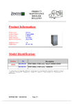
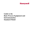
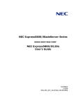
B120a-d 用増設メモリボード
セットアップカード
Memory Module for B120a-d
Setup Card
856-128215-002-00 05-2009 - Rev.01
●作業台の使用
静電気防止マットの上に本体を置き、その上で作業を行ってく
ださい。
●着衣
-ウールや化学繊維でできた服を身につけて作業を行わない
でください。
-静電気防止靴を履いて作業を行ってください。
-取り付け前に貴金属(指輪や腕輪、時計など)を外してくだ
さい。
●部品の取り扱い
-取り付ける部品は本体に組み込むまで静電気防止用の袋
に入れておいてください。
-各部品の縁の部分を持ち、端子や実装部品に触れないでく
ださい。
-部品を保管・運搬する場合は、静電気防止用の袋などに入
れてください。
ステップ 1
856-128215-002-00 * *
**
856-128215-002-00
日本語
●ほこりの多い場所や大気中に硫黄の蒸気が発生する場所及
び、水などの液体のかかるおそれのある場所に置かないでく
ださい。
●強い磁気を発生させるものの近くに置かないでください。
●メモリの端子部分には触れないでください。
本製品を安全にお使いいただくために次の
感電注意 火災注意
注意事項を必ずお守りください。人が死亡す
る、または重傷を負うおそれがあります。
型番
メモリ容量
N8402-042
1GB
(DDR3-1066 1GB DIMM (Registered) x 1 枚)
2GB
(DDR3-1066 2GB DIMM (Registered) x 1 枚)
4GB
(DDR3-1066 4GB DIMM (Registered) x 1 枚)
8GB
(DDR3-1066 8GB DIMM (Registered) x 1 枚)
4GB
(DDR3-1333 2GB DIMM (Unbuffered) x 2 枚)
N8402-043
N8402-044
N8402-045
N8402-046
1.
分解・修理・改造はしない
9.
無理な力を加えるとメモリやコネクタを破損するおそれがあり
ます。まっすぐ、ていねいに差し込んでください。
メモリボードの取り付け
取り外す CPU ブレードのシャットダウン処理をした後、CPU
ブレードの電源を OFF にする。
2.
CPU ブレードをブレード収納ユニットから取り出す。
3.
CPU ブレードをほこりが少なく、静電気防止が施されたシー
トの上に置く。
4.
10.
ケル水素バッテリを取り外さない
●プラグを差し込んだまま取り扱わない
11.
取り外した部品を取り付ける。
12.
CPU ブレードを取り付け、CPU ブレードの電源を ON にする
ことができる状態に戻す。
13.
CPU ブレードの電源を ON にした後、CPU ブレードの POST
(自己診断テスト)中にエラーメッセージが表示されていない
ことを確認する。
14.
BIOS SETUP メニューを起動して「Advanced」-「Memory
Configuration」の順でメニューを選択し、増設したメモリのス
テータス表示が「Normal」になっていることを確認する。
15.
「Advanced」メニューの「Reset Configuration Data」を「Yes」
にする。
ハードウェアの構成情報を更新するためです。
16.
ページングファイルサイズを推奨値以上(搭載メモリ x 1.5)
に設定する(Windows の場合)。
トップカバーを固定しているネジ(2 本)を外す。
はじめに
本増設メモリボードは、NEC BladeServer シリーズ用(以下「CPU
ブレード」と呼ぶ)の増設メモリボードです。
本製品を正しく動作させるために本書の内容をよくお読みになっ
た上で取り付けてください。
プラグを
抜く
(Fig.2a)
5.
CPU ブレード上の電子部品にぶつけないようていねいに取り
扱ってください。
使用上のご注意
静電気対策について
本製品は静電気に弱い電子部品です。取り付け・取り外しの際
は静電気による製品の故障に十分注意してください。
●リストストラップ(アームバンドや静電気防止手袋など)の着用
リスト接地ストラップを手首に巻き付けてください。手に入らな
い場合は部品を触る前に筐体の塗装されていない金属表面
に触れて身体に蓄積された静電気を放電します。
また、作業中は定期的に金属表面に触れて静電気を放電す
るようにしてください。
●作業場所の確認
-静電気防止処理が施された床、またはコンクリートの上で
作業を行います。
-カーペットなど静電気の発生しやすい場所で作業を行う場
合は、静電気防止処理を行った上で作業を行ってください。
カバーをしっかりと持ち、背面側へ少しスライドさせた後、
持ち上げて本体から取り外す。
増設時の注意事項
6.
エアーダクトカバーを固定しているネジを外す。
増設メモリを取り付けるときは、次の事項にご注意ください。
●1CPU 構成時と 2CPU 構成時でメモリの増設順序が違います。
-1CPU 構成時:メモリスロット番号の小さい順に増設
-2CPU 構成時:各 CPU のメモリスロット番号の小さい順に交
互に増設
●容量の大きいメモリからメモリスロット番号の小さい順に増設し
てください。
●メモリの増設単位は N 型番により異なります。
-N8402-042/043/044/045 (Registered DIMM) :1 枚単位
-N8402-046 (Unbuffered DIMM)
:2 枚単位
●Registered DIMM と Unbuffered DIMM を混載した場合、CPU
ブレードは正しく動作しません。
●CPU#2 を実装していない場合、CPU2_DIMM1~CPU2_DIMM6
は使用できません。
レバーを確実に閉じる。
DIMM が複数ある場合には、手順 8~10 と同じ手順でメモリを取
り付ける。
●リチウムバッテリやニッカドバッテリ、ニッ
火気禁止 水ぬれ禁止
メモリを垂直に立てて、コネクタにしっかりと押し込む。
メモリボードには誤挿入防止用のキースロットがあります。
コネクタのキーとキースロットを合わせて差し込んでくださ
い。
(Fig.2d)
●本書に記載されている場合を除き、自分で
破裂注意 分解禁止
(Fig.2c)
●保証書 : 1 枚
●セットアップカード(本書) : 1 冊
第三者への譲渡について
本製品を第三者へ譲渡(または売却)する場合には、本書を一緒
にお渡しください。
メモリを取り付けるコネクタにある左右のレバーを開く。
●メモリボード : 1 枚または 2 枚
ステップ 2
警告
8.
包装箱には、次のものが入っています。確認してください。
メモリボードの取り扱いについて
上記に加えて次の点についてもお守りください。
箱の中身の確認
取り外し
(Fig.2b)
7.
カバーをしっかりと持ち、持ち上げて本体から取り外す。
CPU ブレード上の電子部品にぶつけないようていねいに取り
扱ってください。
メモリを取り外すときは、「メモリボードの取り付け」の手順 1~7
を参照して取り外しの準備をした後、メモリを取り外すコネクタに
ある左右のレバーを開いてください。ロックが解除されメモリを取
り外せます。
また、Unbuffered DIMM を取り外す場合は、ペアを構成するもう
一方のコネクタからメモリを取り外す必要があります。
English
WARNING
Fire
hazard
Electric
hazard
Fire
Explosion
hazard prohibition
Unplug
Water
prohibition
Observe the following instructions to use
the server safely. Failure to follow these
instructions may result in death or serious
personal injury.
■ Do not disassemble, repair, or alter the
server.
■ Do not remove the lithium, nickel
cadmium, or nickel hydrogen battery.
■ Do not handle the CPU blade with the
power cord being plugged to a power
source.
Do not
disassemble
Additional notice
Step1
In addition to the above notes, observe the following
precautions while doing the installation.
■Do not put the memory modules in a dusty place.
■Do not put the memory modules in a place where water or
liquid is likely to splash onto the board.
■Do not put the memory modules in a place where steam of
sulfur occurs in the air.
■Do not put the memory modules in magnetic field.
■Do not touch any terminal pin of memory modules.
NOTE:Make sure of the orientation of the memory.
The connecting side of the memory has a cut-out to
prevent an incorrect insertion.
After you unpack the package, check if it contains the following.
●Memory Module
Code
N8402-042
N8402-043
N8402-044
Transfer of the Unit to a Third Party
When transferring (or selling) the unit to a third party, give
this operation manual to that party.
These contents of this document will be changed without
notice.
Unpacking
N8402-045
N8402-046
Memory Capacity
1GB
(DDR3-1066 1GB DIMM (Registered) x 1)
2GB
(DDR3-1066 2GB DIMM (Registered) x 1)
4GB
(DDR3-1066 4GB DIMM (Registered) x 1)
8GB
(DDR3-1066 8GB DIMM (Registered) x 1)
4GB
(DDR3-1333 2GB DIMM (Unbuffered) x 2)
●Memory Module Setup Card (This manual)
Key slot
Key
(Fig.2d)
10. Close the lever firmly.
If you need to install two or more memorys, install them
according to steps 8 through 10.
11. Install the components having been removed.
12. Make sure that no error message appears on the POST
screen.
13. Run SETUP and select [Advanced] → [Memory
Notes on Installing the memory
ANTI-STATIC MEASURES
The CPU blade contains electronic components sensitive to
static electricity. Avoid failures caused by static electricity
when installing or removing any optional devices.
■ Wear a wrist strap (an arm belt or anti-static glove).
Wear a wrist strap on your wrist. If no wrist strap is
available, touch an unpainted metal part of the cabinet
before touching a component to discharge static electricity
from your body.
Touch a metal part regularly when working with
components to discharge static electricity.
■ Select a suitable work space.
– Work with the CPU blade on the anti-static or concrete
floor.
– When you work with the CPU blade on a carpet where
static electricity is likely to be generated, make sure take
anti-static measures beforehand.
■ Use a work table.
Place the CPU blade on an anti-static mat to work with it.
■ Cloth
– Do not wear a wool or synthetic cloth to work with the
CPU blade.
– Wear anti-static shoes to work with the CPU blade.
– Take off any jewels (a ring, bracelet, or wrist watch)
before working with the CPU blade.
■ Handling of components
– Keep any component in an anti-static bag until you
actually install it to the CPU blade.
– Hold a component by its edge to avoid touching any
terminals or parts.
– To store or carry any component, place it in an anti-static
bag.
Step2
Preface
This memory module is an expansion kit for your system.
The memory module substaintilly increases your system
speed and responsiveness. Users benefit through increased
productivity - complete more work in a day or spend the time
saved to improve work quality.
Read this guide carefully for proper installation.
Adding Order and Precautions
■ Adding order depends on the number of CPUs installed.
– 1-CPU configuration:
Install the memory starting from the smallest DIMM slot
number.
– 2-CPU configuration:
Alternately install the memory starting from the smallest
DIMM slot number of each CPU.
■ Install the memory starting from the largest capacity and
from the smallest slot number.
■ Adding unit depends on N code assigned to DIMM.
– N8402-042/043/044/045 (Registered DIMM):
Can be installed one by one.
– N8402-046 (Unbeffered DIMM):
Must be installed two in pair.
■ The CPU blade does not operate correctly if Registered
DIMM and Unbuffered DIMM are mixedly installed.
■ If the CPU blade does not have CPU#2 installed, DIMM
slots CPU2_DIMM1 to CPU2_DIMM6 are unavailable.
Installing the memory
Configuration] to verify that the installed memory shows
the status "Normal".
14. Set [Advanced] – [Reset Configuration Data] in the
1.
After the shutdown processing for the CPU blade to be
removed, turn off the power of the CPU blade.
2.
Take the CPU blade out from the Blade Enclosure.
Refer to the User's Guide of the Blade Enclosure.
3.
Put the CPU blade on an anti-static sheet with little dust.
4.
Remove the two screws fixing the top cover.
5.
Firmly hold the cover, move it slightly toward the rear of
the blade, then lift the cover to remove it from the CPU
blade.
IMPORTANT:Handle the cover carefully so as not
to make it contact with any electronic devices on
the CPU blade.
6.
Remove the screws from the air duct cover.
(see Fig.2b)
7.
Firmly hold the cover, and lift it to remove.
IMPORTANT:Pay attention not to make the cover
hit any electronic component on the CPU blade.
8.
Open the levers at both ends of the DIMM socket.
(see Fig.2c)
9.
Push the memory into the socket straight.
If the memory is inserted into the DIMM socket, the lever
is automatically closed.
IMPORTANT:Use extreme care when installing a
memory. Applying too much pressure can damage
the socket. Keyed memory insert only one way.
[Advanced] menu to [Yes].
This is required to update the hardware configuration
information.
15. Set the paging file size to a value larger than the
recommended value (installed memory * 1.5) (for
Windows).
Removal
To remove the memory, provide the preparation of the
removal following steps 1 to 7 in the installation procedure
and open the levers at both ends of the DIMM socket to be
removed. The lock is released to allow you to remove the
memory.
If you are removing Unbuffered memory, remove the
pairing memory from another memory connector.