1
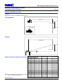
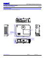
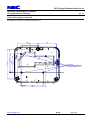
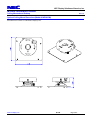
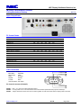
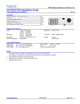
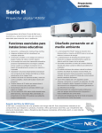
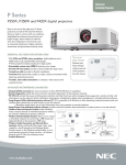
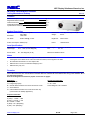
NEC Display Solutions of America, Inc. M322W Installation Guide Ceiling Mounted and Desktop Rev 1.0 Contents Product Description, Lens Specs, Notes and Formulas Diagrams & Distance Charts Cabinet Dimensions Ceiling Mount Dimensions Input Panel and Control Codes Pg 1 Pg 2 Pg 3-4 Pg 5 Pg 6 Product Description Dimensions: 14.5” (W) x 4.3” (H) x 11.5” (D) Weight: 8.0 lbs Resolution: 1 Chip DLP Projector 0.65” DMD 1280 x 800 Fan Noise: 38 dB / 30dB @ 1 meter Brightness: 3200 Lumens BTU’s: 1024 BTU/hour Type: Power Consumption: 286W (max) Lens Specifications Throw Ratio: Offset Angle: 1.2 – 2.0:1 (for 100” diagonal) 10.5° - 18.6° (for 100” diagonal) Focal Length: F/#: 17.09mm – 29.05mm 2.4 - 3.1 Screen Sizes: 30” - 300” diagonal (16:10) Manual Focus/Manual Zoom Notes For screen sizes not indicated on the projection tables, use the formulas below. If the figures on the tables do not match the results of formulas, use the figures in the table. All calculations are based on a 16:10 aspect ratio. Distances are in inches, for millimeters multiply by 25.4. Distances may vary 5%. Formulas The Projection Formulas use the image width for calculation. For proper projection placement, determine the image width for the desired screen size. Use the Screen Formulas below to calculate all screen dimensions. Plug in the width for “W” in the Projection Formulas. Refer to the diagrams and charts for popular screen sizes on page 2: Definitions: W = Image Width H = Image Height (size) B = Vertical distance between lens center and screen center C = Throw distance D = Vertical distance between lens center and screen top (screen bottom for desktop application) 16:10 Screen Formulas: W = H x 16/10 H = W x 10/16 Screen Diagonal = W x 18.868/4 Projection Formulas: B = 0.39W C (wide) = 1.236W – 1.966 C (tele) = 2.101W – 3.105 D = 0.078W – 0.2856 α (wide) = tanˉ¹ (B/C(wide)) α (tele) = tanˉ¹ (B/C(tele)) www.necdisplay.com M311W Page 1 of 6 NEC Display Solutions of America, Inc. M322W Installation Guide Ceiling Mounted and Desktop Rev 1.0 Diagrams and Distance Charts The following shows the proper relative positions of the projector and screen. Refer to the table to determine the position of installation. Distances are in inches. For millimeters multiply by 25.4. Ceiling Mounted C Throw D istance 5.43 5.56 Lens C tr D Screen Top B Lens Offset F rom Mount Pipe Screen C tr 3.31 Desktop C Throw D istance Screen C tr B Screen Bottom D Lens C tr 2.38" Distance Chart for popular 16:10 screens Note: For screen sizes not indicated on the projection tables, use the formulas on page 1. www.necdisplay.com Screen Size (16:10) B Diagonal Width(W) Height (H) inches inches inches 57 48 30 inches 19 C w ide - tele inches 57 98 D inches 4 α w ide - tele degrees 18.1 - 10.8 66 56 35 22 67 - 115 5 18.0 - 10.8 68 58 36 22 69 - 118 5 18.0 - 10.8 75 64 40 25 77 - 131 5 17.9 - 10.8 79 67 42 26 81 - 138 6 17.9 - 10.7 85 72 45 28 87 - 148 6 17.9 - 10.7 92 78 49 31 95 - 162 6 17.9 - 10.7 98 83 52 32 101 - 172 7 17.8 - 10.7 102 86 54 34 105 - 178 7 17.8 - 10.7 111 94 59 37 115 - 195 8 17.8 - 10.7 113 96 60 37 117 - 199 8 17.8 - 10.7 123 104 65 41 127 - 215 8 17.8 - 10.7 125 106 66 41 129 - 219 9 17.8 - 10.7 147 125 78 49 152 - 259 10 17.7 - 10.6 149 126 79 49 154 - 262 10 17.7 - 10.6 213 181 113 71 222 - 377 14 17.7 - 10.6 255 216 135 84 265 - 451 17 17.6 - 10.6 M311W Page 2 of 6 NEC Display Solutions of America, Inc. M322W Installation Guide Ceiling Mounted and Desktop Rev 1.0 Cabinet Dimensions The following drawings show the cabinet dimensions. Dimensions are in inches. For millimeters multiply by 25.4. AC IN L ET 1 1 .5 1 1 .3 L AMP ZOOM LEVER FOC U S L EVER AIR IN TAKE 1 4 .5 L EN S C EN TER L EN S C OVER IR R EC EIVER 2.299 4.232 3.839 www.necdisplay.com 2.378 EXH AU ST M311W Page 3 of 6 NEC Display Solutions of America, Inc. M322W Installation Guide Ceiling Mounted and Desktop Rev 1.0 Cabinet Dimensions (continued) The following drawings show the cabinet dimensions. Dimensions are in inches. For millimeters multiply by 25.4. 5.87 7.417 5.906 5.118 9.484 6.571 5.232 M4 x 8 Depth FOR CEILING MOUNT KIT 0.197 www.necdisplay.com 6.89 7.677 M311W Page 4 of 6 NEC Display Solutions of America, Inc. M322W Installation Guide Ceiling Mounted and Desktop Rev 1.0 Optional Ceiling Mount Dimensions (Model #: MP300CM) The following drawings show the ceiling mount dimensions. Dimensions are in inches. For millimeters multiply by 25.4. www.necdisplay.com M311W Page 5 of 6 NEC Display Solutions of America, Inc. M322W Installation Guide Ceiling Mounted and Desktop Rev 1.0 Input / Output Panel PC Control Codes Function POWER ON POWER OFF INPUT SELECT COMPUTER1 INPUT SELECT HDMI 1 INPUT SELECT HDMI 2 INPUT SELECT VIDEO INPUT SELECT VIEWER INPUT SELECT NETWORK INPUT SELECT USB DISPLAY PICTURE MUTE ON PICTURE MUTE OFF SOUND MUTE ON SOUND MUTE OFF PROJECTOR INFORMATION REQUEST ERROR STATUS REQUEST INFORMATION REQUEST Code Data 02H 00H 02H 01H 02H 03H 02H 03H 02H 03H 02H 03H 02H 03H 02H 03H 02H 03H 02H 10H 02H 11H 02H 12H 02H 13H 00H BFH 00H 88H 03H 8AH 00H 00H 00H 00H 00H 00H 00H 00H 00H 00H 00H 00H 00H 00H 00H 00H 00H 00H 00H 00H 00H 00H 00H 00H 00H 00H 00H 00H 00H 00H 00H 00H 00H 00H 02H 02H 02H 02H 02H 02H 02H 00H 00H 00H 00H 01H 00H 00H 02H 03H 01H 01H 01H 01H 01H 01H 01H 12H 13H 14H 15H 02H 88H 8DH 01H 1AH 12H 06H 1FH 20H 22H 09H 22H AAH 0EH 27H 28H 2AH C2H Note: Contact your NEC rep for codes not listed. Cable Connection Communication Protocol: Baud Rate: 38400 bps Data Length: 8 bits Parity: No Parity Stop Bit: One Bit X on/off: None Communications: Full duplex To TxD of PC To RxD of PC To GND of PC 1 2 6 7 3 4 8 PC Control Connector (D-Sub 9P) 5 9 To RTS of PC To CTS of PC NOTE 1 : Pins 1, 4, 6, and 9 are used inside the projector. NOTE 2: For long cable runs it is recommended to set communication speed within the projector to 9600 bps. NOTE 3: Jumper “Request to Send” and “Clear to Send” together on both ends of the cable to simplify cable connection. www.necdisplay.com M311W Page 6 of 6