1
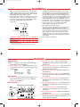
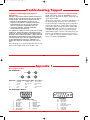
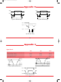
User’s Manual
13" True Color TFT LCD Monitor
13" True Color TFT LCD Monitor
NEC Technologies, Inc.
1255 N. Michael Drive
Wood Dale, Illinois 60191-1094
Part No.
Printed in U.S.A.
LCD1280 10/29/99 9:25 AM Page 1
LCD1280 10/29/99 9:25 AM Page 2
Information for LCD1280
WARNING
TO PREVENT FIRE OR SHOCK HAZARDS, DO NOT EXPOSE THIS UNIT TO RAIN
OR MOISTURE. ALSO, DO NOT USE THIS UNIT’S POLARIZED PLUG WITH AN
EXTENSION CORD RECEPTACLE OR OTHER OUTLETS, UNLESS THE PRONGS CAN
BE FULLY INSERTED.
REFRAIN FROM OPENING THE CABINET AS THERE ARE HIGH VOLTAGE
COMPONENTS INSIDE. REFER SERVICING TO QUALIFIED SERVICE PERSONNEL.
CAUTION
RISK OF ELECTRIC SHOCK
DO NOT OPEN
CAUTION: TO REDUCE THE RISK OF ELECTRIC SHOCK, DO NOT REMOVE
COVER (OR BACK). NO USER SERVICEABLE PARTS INSIDE. REFER
SERVICING TO QUALIFIED SERVICE PERSONNEL.
This symbol warns user that uninsulated voltage within the unit may
have sufficient magnitude to cause electric shock. Therefore, it is
dangerous to make any kind of contact with any part inside this unit.
This symbol alerts the user that important literature concerning the
operation and maintenance of this unit has been included.
Therefore, it should be read carefully in order to avoid any problems.
FCC Information
The Federal Communications Commission Radio Frequency
Interference Statement includes the following warning:
FCC Rules. These limits are designed to provide reasonable
protection against harmful interference when the equipment is
operated in a commercial environment. This equipment generates, uses, and can radiate radio frequency energy, and, if not
installed and used in accordance with the instruction manual,
may cause harmful interference to radio communications.
Operation of this equipment in a residential area is likely to
cause harmful interference in which case the user will be
required to correct the interference at his own expense.
DOC Compliance Notice
This digital apparatus does not exceed the Class A limits for
radio noise emissions from digital apparatus set out in the Radio
Interference Regulations of the Canadian Department of
Communications.
DOC Avis de Conformation
Le presént appareil numérique n’émet pas de bruits radioélectriques dépassant les limites applicables aux appareils
numériques de la Class A prescrites dans le Réglement sur le
brouillage radioélectrique édicté par le ministére des
Communications du Canada.
Note: This equipment has been tested and found to comply with
the limits for a Class A digital device, pursuant to part 15 of the
Contents
Introduction
Contents of Package
Introduction to the NEC LCD1280
True Color Monitor
Analog Interface
Reduced Footprint
Low Power Consumption
ErgoDesign™
Reduced Emissions
LCD1280 Specifications
Installation
Recommended Use
Connection to Graphics Cards
using BNC cables
Controls
Front Controls
Side Control
Rear Controls
1
1
1
1
1
2
2
2
3
5
5
5
7
7
7
7
Troubleshooting/Support
Troubleshooting Chart
Technical Support
BBS
FastFacts™
Warranty
Appendix 1
Pin Assignment Table
Appendix 2
Signal Timings
Appendix 3
Signal Levels
9
9
10
10
10
10
13
13
14
14
17
17
References
18
Index
18
LCD1280, ErgoDesign, IPM, Reduced Magnetic Field, and FastFacts are trademarks of NEC Technologies, Inc. NEC is a registered trademark of NEC Corporation.
Copyright ©1995 by NEC Technologies, Inc. All other brand or product names are trademarks or registered trademarks of their respective holders.
LCD1280 10/29/99 9:25 AM Page 3
Introduction
formance necessary for today’s sophisticated Windows,
Macintosh, Silicon Graphics, Sun and other workstation
applications.
Contents of Package
Congratulations on your purchase of the NEC LCD1280™
True Color monitor!
In addition to offering support for VGA graphics mode
(640 x 480), the LCD1280 supports WS high resolution
mode (1280 x 1024). The LCD1280 automatically detects
and changes between WS high resolution mode and VGA
graphics mode. The LCD1280 can display an infinite
number of colors in its high resolution mode.
Included with your LCD1280 monitor are the following items:
1. NEC LCD1280 (Model #LA-1331JSW) True Color monitor.
2. AC power cable.
3. Video signal cable (15 pin mini D-sub male to 5
branched BNC male).
4. User’s Manual.
Analog Interface
Remember to save the original box and packing materials
to transport or ship this monitor.
Because the LCD1280 accepts an analog input, a graphics
card with digital output is not required. The same graphics board can be used to drive the LCD1280 or a standard
CRT monitor. The analog interface also provides the LCD
with its true-color capability. Unlike digital panels, the
LCD1280 is able to display a continuous spectrum of
“true” colors.
Introduction to the NEC LCD1280
True Color Monitor
The LCD1280 monitor provides superior display
performance, a reduced footprint and the flexibility and
adaptability required by today’s complex computing
environments.
Reduced Footprint
The LCD1280 monitor offers nearly the same active
display size as a conventional 15-inch CRT (13.8” diagonal
viewable image size) at 40% of the depth and 30% of the
weight. With a depth of less than seven inches, the reduced
footprint of the LCD1280 provides the ideal solution for
applications requiring a large display and high resolution but
where space and weight are of particular concern.
The LCD1280 features a 13-inch (diagonal viewable
image size), active matrix, true-color, thin-film-transistor,
liquid crystal display to provide superior display performance with a reduced footprint. Less than seven inches in
depth, the LCD1280 monitor is ideal for environments with
space and weight constraints that require superior image
quality. The LCD1280 also delivers the outstanding per1
LCD1280 10/29/99 9:25 AM Page 4
Introduction
Low Power Consumption
The LCD1280 has been designed with NEC’s IPM™ (Intelligent
Power Manager) System. When utilized with an Energy Star
system or video card, the LCD1280's IPM System is an innovative power saving utility that complies with both the EPA’s
Energy Star requirements and Europe’s NUTEK’s power management requirements.
different IPM modes. The following is the description of the
LED indicator for the IPM power saving modes:
Mode
ON
Stand By & Suspend
Power Switch, OFF
With a maximum power consumption of only 50 watts in
its on mode, the LCD1280 monitor consumes up to 50%
less power and emits less heat than conventional CRTs.
In its power saving mode, the LCD1280 consumes less
than 8 watts. All this translates into energy savings, environmental protection, reduced emissions and reduced air
conditioning costs of the work environment.
LED Indicator
Green
Amber
No Light
Power Consumption
Typical: 45 watts
Typical: Less than 8 watts
No Power Used
ErgoDesign™
The LCD1280 utilizes NEC’s ErgoDesign philosophy to
make the panel more comfortable and easy to use. The
panel’s power and brightness control are positioned within
easy reach, and the tilt base adjusts to each individual’s
preferred angle of vision. The LCD1280 monitor’s cabinet
design and aesthetics look good from all angles.
The LCD1280 monitor follows the Video Electronics Standard
Association (VESA) approved DPMS power-down signaling
method. VESA’s Display Power Management Signaling (DPMS)
method which is endorsed by the EPA is the power-down
process a system should use to communicate to the monitor to
save power. Power-down functions can only be utilized with
an Energy Star system or video card which adheres to the
VESA DPMS standard. By using the monitor’s horizontal and
vertical SYNC signals, the monitor can be prompted into the
Reduced Emissions
Incorporating NEC’s own Reduced Magnetic Field™ technology, the LCD1280 has minimal field emissions and
follows the strictest magnetic field, alternating electric field
and electro-static recommendations of the Swedish Board
for Technical Accreditation, or SWEDAC (previously
known as MPR, National Board for Measurement and
Testing). The LCD1280 conforms to SWEDAC MPR
1990:8 (MPR II) Testing Methods for Emissions. These
standards are the most restrictive guidelines in the world.
2
LCD1280 Specifications
Display:
13-inch (13.0” viewable image size), active matrix, thin film transistor (TFT), liquid crystal
display (LCD); 0.201mm dot pitch; RGB vertical stripe color filter arrangement; 100 cd/m2
white luminance, typical; 100:1 contrast ratio, typical
Compatibility:
640 x 480: VGA, 60 Hz vertical refresh
1280 X 1024: WS high resolution, 60 Hz vertical refresh
Synchronization Range:
VGA:
High
Resolution:
Horizontal:
Vertical:
Pixel Frequency:
Horizontal:
Vertical:
Pixel Frequency
(switchable):
Resolution:
Horizontal:
Vertical:
1280 dots
1024 lines
Active Display Area:
Horizontal:
Vertical:
257.3 mm, 10.13”
205.8 mm, 8.10”
Minimum Viewing Angles:
Input Signal:
Up 10°, Down 30°, Right 30°, Left 30°
29.5 kHz to 33.5 kHz
> 60 Hz
25.175 MHz ± 50 ppm
63.0 kHz to 66.4 kHz
> 60 Hz
107.5 MHz ± 50 ppm, or
107.352 MHz ± 50 ppm
Video: Analog Red, Green, Blue
Input Impedance: 75 ohms +/– 5% (at 100 kHz)
Sync:
Separate sync. TTL level
Horizontal sync: positive/negative
Vertical sync: positive/negative
Composite sync: TTL level, positive/negative
Composite sync. on green video: 0.3 Vp-p (+/– 3 dB) negative
(Video 0.7 Vp-p positive)
3
LCD1280 10/29/99 9:25 AM Page 5
Introduction
LCD1280 Specifications
Display Colors:
User Controls:
Signal Cable:
Power Supply:
Power Consumption:
Dimensions (W, H, D):
Weight:
Unlimited colors (depends on graphics interface and/or application)
Tilt Rotation:
Up: 25 degrees
Down: 5 degrees
Environmental:
Operating temperature:
Storage temperature:
Power, brightness, horizontal position, vertical position, clock delay adjust
15-pin mini D-sub male to 5 branched BNC male
AC 90 to 264 V worldwide input, 48 to 62 Hz
Typical: 45 watts in ON mode, Under 8 watts in power saving mode.
344 x 325 x 171 mm/13.5 x 12.8 x 6.7 inches
Net: 5.0 kg /11.0 lbs.
Gross: 6.8 kg /15.0 lbs.
10°C to 30°C, 50°F to 86°F; humidity 80% maximum
–10°C to 60°C, 14°F to 140°F, humidity 85% maximum
Note: All technical specifications are subject to change without notice.
4
Installation
a high resolution pixel frequency of 107.5 MHz ± 50 ppm
or 107.352 MHz ± 50 ppm. Silicon Graphics’ INDIGO2
workstation does not require a graphics card. (For a current
list of compatible platforms please call NEC’s FastFacts at
1-800-366-0476 and request document #52301280).
To attach the monitor to your system, follow these instructions:
Recommended Use
For optimum performance, please note the following when
setting up and using the LCD1280 color monitor:
• The optimum monitor position is facing away from direct sunlight.
• Match the monitor’s brightness to the ambient room brightness.
The brightness control should be adjusted to a point where the
overall background area just begins to disappear.
• If possible, use a white background and black text to ease eye
strain.
• Do not place any heavy objects on the power cord. Damage
to the cord may cause shock or fire.
• Handle with care when transporting.
• Use the monitor in a clean and dry area.
• Clean the LCD surface with a lint-free, non-abrasive cloth and a nonalcohol, neutral, non-abrasive cleaning solution or glass cleaner.
• For optimum performance, allow 20 minutes for warm-up.
• Avoid displaying fixed patterns on the monitor for extremely long
periods of time to avoid after-image effects.
1. Turn off the power to the monitor and computer.
2. If necessary, install the graphics card and drivers.
Determine the pixel frequency (DOT clock) output and the
SYNC method used by the graphics card or system. For
more information, refer to the graphics card or system manual
or the FastFacts document referred to above.
3. Make sure the H-SEL switch on the rear of the panel
is positioned to the appropriate pixel frequency (if you are
not sure, refer to the board manual or documents). Under
most cases, a timing of 107.5 MHz will apply (Mode 1). For
SGI’s INDIGO2, a timing of 107.352 MHz applies (Mode 2).
1
2
H-SEL
Pixel Frequency (DOT clock):
H-SEL Mode 1 — 107.5 MHz
H-SEL Mode 2 -— 107.352 MHz
4. Make sure the SYNC switch on the rear of the panel
is positioned to the appropriate mode.
SYNC
Input Mode:
OFF — Separate Sync/
Composite Sync
ON — Sync on Green
OFF ON
Connection to Graphics Cards using BNC cables
The NEC LCD1280 color monitor complements a host of
computing platforms. However, because the LCD1280 is a
high resolution, full color analog monitor, it may require
the use of a graphics card (sometimes referred to as a
video card, video adapter or graphics board) that supports high resolution graphics (1280 x 1024), 24-bit color
(16.7M colors), delivers an analog output, and which has
5
LCD1280 10/29/99 9:25 AM Page 6
Installation
5. Make sure the appropriate BNC cable is used. Should the
graphics adapter require a connector other than the 15 pin
mini D-sub male included with the monitor, please call NEC
at (800) 820-1230. Connect cable to system.
6. Connect BNC cables as follows according to the input video
mode selected above. (Note: incorrect cable connections
may result in irregular operation, damage display quality/
components of LCD module, and/or shorten the
module’s life.)
Connect the red BNC cable to the BNC connector on the
monitor labeled R. The green BNC cable should be connected to the BNC connector on the monitor labeled G. The
blue BNC cable should be connected to the BNC connector
on the monitor labeled B. If you have a fourth BNC connector (Composite Sync), connect it to the BNC connector on the
monitor labeled H/CS. If you have a fifth BNC connector
(Vertical Sync), connect it to the BNC connector on the monitor labeled VS. Please see Appendix 1 for pin assignments.
7. Connect one end of the power cable to the LCD1280
monitor and the other end to the power outlet.
8. Turn on the monitor and the computer.
Note: If the settings and connections were made properly,
the LED on the front of the LCD1280 will show green.
If the LED displays an amber color, the monitor is not receiving the appropriate input. Please make certain that the
above settings were made properly. If the LED continues
to display an amber color or the monitor is not displaying
a stable image, please refer to the Troubleshooting section
of this manual.
9. This completes the installation.
H Sync/Composite Sync
V Sync
SYNC
H/CS
VS
OFF ON
R
G/SYNC
B
Sync Mode Select
Blue
Red
Green / Sync on Green
Input Video Mode
H/CS
O
O
X
Separate Sync
Composite Sync
Sync on Green
VS
O
X
X
R G/SYNC B
O
O
O
O
O
O
O
O
O
O - BNC connector is utilized; X - BNC connector is not utilized
6
Controls
SYNC Mode Select Switch: allows selection between
Standard mode (OFF) and Sync on Green (ON)
priority mode.
H-SEL Pixel Frequency Select Switch: selects the external
pixel clock source for WS timing 1 (107.5 MHz) or
WS timing 2 (107.352 MHz).
WS Clock Delay Adjust (H-C): adjustment of WS pixel
clock delay rate.
Rough WS Horizontal Adjust (H-H1): rough adjustment
for horizontal position of WS mode (16 dot increment
per operation).
Fine WS Horizontal Adjust (H-H2): fine adjustment for
horizontal position of WS mode (1 dot increment per
operation).
Rough WS Vertical Adjust (H-V1): rough adjustment for
vertical position of WS mode (16 line increment per
operation).
Fine WS Vertical Adjust (H-V2): fine adjustment for
vertical position of WS mode (1 line increment per
operation).
VGA Clock Delay Adjust (V-C): adjustment of VGA pixel
clock delay rate.
Rough VGA Horizontal Adjust (V-H1): rough adjustment
for horizontal position of VGA mode (32 pixel / 16
dot increment per operation).
Front Controls:
Brightness: slide type control adjusts the overall image
and background screen brightness.
LED Power Indicator Light: indicates the monitor’s power
mode. Each mode reduces the amount of power used
by the monitor:
Mode
ON
Stand By & Suspend
Power Switch, OFF
Light
green
amber
no light
Side Control:
Power Switch: push type button located on right side of
monitor base turns the power on or off. When the
power is on, the LED is lit.
Rear Controls:
Display Position / Clock Delay Adjust
H-SEL
Pixel Frequency
Select
H-C
V-H2
V-V2
V-C
V-V1
V-H1
H-V2
H-H2
H-H1 H-V1
0
2
E
6
A
H/CS
VS
G/SYNC
B
SYNC
4
C
OFF
ON
8
R
Sync Mode Select
7
LCD1280 10/29/99 9:25 AM Page 7
Controls
Fine VGA Horizontal Adjust (V-H2): fine adjustment for
horizontal position of VGA mode (2 pixel / 1 dot
increment per operation).
Rough VGA Vertical Adjust (V-V1): rough adjustment for
vertical position of VGA mode (32 pixel / 16 line
increment per operation).
Fine VGA Vertical Adjust (V-V2): fine adjustment for
vertical position of VGA mode (2 pixel / 1 line
increment per operation).
8
Troubleshooting/Support
Problem
Check These Items
No Picture
•
•
•
•
•
Image is unstable or swimming
is apparent
• Signal cable should be completely attached to the computer.
• Check the monitor and your video card with respect to compatability and recommended
signal timings (Please see FastFacts document #52301280 and Appendix 2).
• Check the SYNC Switch and H-SEL Switch for their correct position.
LED on the monitor is not lit
(no green or amber color can
be seen)
Picture is not focused or
jitter is present
• Power Switch should be in the ON position and the power cord should be connected.
• Make certain the computer is not in a Power-Saving mode (touch the keyboard or mouse).
Display image is not centered
• Use WS and VGA horizontal and vertical adjustment controls located on the rear of the
panel to adjust centering.
The signal cable should be completely connected to the video card/computer.
The video card should be completely seated in its slot.
Power Switch and computer power switch should be in the ON position.
Check BNC connectors to make certain that each connector has been attached correctly.
Check H-SEL Switch and SYNC Switch to make certain that they are in the
correct position according to the Installation section of this manual.
• Use WS Clock Delay Adjust (H-C) or VGA Clock Delay Adjust (V-C) to focus
display. When the display mode will be changed, the clock settings may need to be
re-adjusted.
9
LCD1280 10/29/99 9:25 AM Page 8
Troubleshooting/Support
Technical Support
FastFacts™
FastFacts system is an easy-to-use, automated facsimile
service that provides you with information whenever you
need it, 24 hours a day, seven days a week. You can call
the FastFacts system with your touchtone telephone, order a
catalog listing the available documents, or order the document you need. Within minutes, your requested information
will be sent to your fax machine. The information includes:
If the problem persists, call NEC Technologies, Inc. at
(800) 388-8888. Before you call, please follow these
instructions to allow for faster service:
• Call from a location at or near your monitor.
• Know the name and model number of your monitor:
LCD1280, LA-1331JSW
• Know the name and the model number of the computer
you are using, and have its manual nearby.
• Know the name of the graphics card you are using, and
have its manual nearby.
• If it is more convenient to fax a question to NEC’s
Technical Support, the fax number is (508) 635-4666.
-
The BBS
product brochures
installation procedures
quick reference guides
troubleshooting information
compatibility charts
To contact FastFacts, dial: (800) 366-0476.
The
NEC Remote Bulletin Board System (BBS) is a great
way to keep in touch with NEC. It is an electronic service
accessible with your system and a modem. You can tell us
things about yourself, your experience with the product,
and leave messages requesting on-line help. Also, the
BBS keeps you up to date on the latest NEC products and
lets you download new product information when it is
available.
To contact the BBS using any computer with a modem,
dial: (508) 635-4706.
Communications parameters are: 300/1200/2400/9600
bps, no parity, 8-data bits, 1 stop bit.
Limited Warranty
NEC Technologies, Inc. (hereinafter NECTECH) warrants
this Product to be free from defects in material and workmanship and agrees to repair or replace any part of the
enclosed unit which proves defective under these terms
and conditions.
How Long is the Warranty
Parts and labor are warranted for one (1) year from the
date of the first consumer purchase. Spare parts are warranted for ninety (90) days.
10
Who is Protected
5. This warranty covers only NECTECH-supplied components.
Service required as a result of third party components is not
covered under this warranty.
What is Covered and What is not Covered
What NECTECH Will Pay For and What We
Will Not Pay For
This warranty may be enforced only by the first consumer
purchaser and is not transferable.
Except as specified below, this warranty covers all defects
in material or workmanship in this Product. The following
are not covered by this warranty:
NECTECH will pay labor and material expenses for covered
items, but we will not pay for the following:
1. Any Product which is not distributed in the U.S.A. or
Canada by NECTECH or which is not purchased in the
U.S.A. or Canada by the first consumer purchaser.
2. Any Product on which the serial number has been defaced,
modified or removed.
3. Damage, deterioration or malfunction resulting from, but not
limited to:
a. Accident, misuse, abuse, neglect, fire, water, lightning
or other acts of nature, improper storage, unauthorized
Product modification, or failure to follow instructions
supplied with the Product.
b. Alteration, repair or attempted repair by anyone not
authorized by NECTECH.
c. Any shipment of the Product (claims must be presented
to the carrier).
d. Removal or installation of the Product.
e. Any other cause which does not relate to a Product
defect.
4. Cartons, carrying cases, batteries, external cabinets,
magnetic tapes, or any accessories used in connection with
the product.
1. Removal or installation charges.
2. Costs of initial technical adjustments (set-up), including adjustment of user controls.
3. Payment of shipping and related charges incurred in returning
the Product for warranty repair.
How You Can Get Warranty Service
This product must be returned to a NECTECH factory for
repair. It shall be your obligation and expense to ship the
Product, freight prepaid, to a facility authorized by NECTECH
to render the warranty services in either the original package
or a similar package affording an equal degree of protection.
NECTECH may require that you provide the original bill of
sale or receipt as proof of purchase in order to obtain warranty service. Please retain such proof of purchase with your
records.
11
LCD1280 10/29/99 9:25 AM Page 9
Troubleshooting/Support
Limitation of Damages and Implied
Warranties
For Information, Telephone 1-800-388-8888
NOTE: All Products returned to NECTECH for service
MUST have prior approval; this may be obtained by calling the above number.
NECTECH’S SOLE LIABILITY FOR ANY DEFECTIVE PRODUCT IS
LIMITED TO THE REPAIR OR REPLACEMENT OF THE PRODUCT
AT OUR OPTION. NECTECH SHALL NOT BE LIABLE FOR:
This Product is warranted in accordance with the terms of
this limited warranty. Consumers are cautioned that
Product performance is affected by system configuration,
software, the application, customer data, and operator
control of the system, among other factors. While NEC
TECHNOLOGIES, INC. Products are considered to be
compatible with many systems, the specific functional
implementation by the customers of the Product may vary.
Therefore, the suitability of a Product for a specific purpose or application must be determined by the customer
and is not warranted by NECTECH.
1. DAMAGE TO OTHER PROPERTY CAUSED BY ANY
DEFECTS IN THIS PRODUCT, DAMAGES BASED UPON
INCONVENIENCE, LOSS OF USE OF THE PRODUCT,
LOSS OF TIME OR DATA, COMMERCIAL LOSS; OR
2. ANY OTHER DAMAGES, WHETHER INCIDENTAL,
CONSEQUENTIAL OR OTHERWISE.
THIS WARRANTY IS EXCLUSIVE AND IS IN LIEU OF ALL OTHER
WARRANTIES, EXPRESS OR IMPLIED, INCLUDING BUT NOT
LIMITED TO, THE IMPLIED WARRANTIES OF MERCHANTABILITY
OR FITNESS FOR A PARTICULAR PURPOSE. SOME STATES DO
NOT ALLOW THE EXCLUSION OF IMPLIED WARRANTIES OR
THE LIMITATION OR EXCLUSION OF LIABILITY FOR INCIDENTAL OR CONSEQUENTIAL DAMAGES. THEREFORE, THE
ABOVE EXCLUSIONS OR LIMITATIONS MAY NOT APPLY TO
YOU.
This warranty gives you specific legal rights, and you may
also have other rights which vary from state to state.
12
Appendix 1
Pin Assignment Table
For the Monitor:
H/CS
VS
G
B
R
BNC Number
1
2
3
4
5
Separate SYNC Composite SYNC
Horizontal
Composite SYNC
Vertical
No Connection
Red
Red
Green
Green
Blue
Blue
Sync on Green
No Connection
No Connection
Red
Green with SYNC
Blue
For the Graphics Board:
2
1
6
11 12
4
3
7
8
5
9
13 14
10
A1
Red Video
Green Video
Blue Video
Reserved
Reserved
Red Ground
Green Ground
Blue Ground
9
10
11
12
13
14
15
A1
A2
A3
Reserved
Digital Ground
Reserved
Reserved
Horizontal SYNC
Vertical SYNC
Reserved
3
4
5
8
9
10
13
9
8
7
1
15
IBM VGA
15-pin mini D-Sub female
1
2
3
4
5
6
7
8
6
2
3
10
4
5
A2
A3
13W3 Male
Red Video
Green Video
Blue Video
Sense Code
Return for Sense Code
Composite Sync
Sense Code
Sense Code
Sync Return
LCD1280 10/29/99 9:25 AM Page 10
Appendix 2
Signal Timings
Input Signal Timings (WS High Resolution Mode)
Item
Abbreviation
Monitor Rating
Pixel frequency
fc
107.5MHz ± 50ppm
9.302nsec/pixel
107.352HHz ± 50ppm
9.315nsec/pixel
Horizontal frequency
fh
64.60KHz
Line Time total
Th
15.479usec
1664CLK
15.649esec
1680CLK
Horizontal active display
Thd
11.907usec
1280CLK
11.923usec
1280CLK
Horizontal sync pulse
Thp
1.786usec
192CLK
1.118usec
120CLK
Horizontal baack porch
Thb
1.488usec
160CLK
2.329usec
250CLK
Horizontal front porch
Thf
0.298usec
32CLK
0.279usec
30CLK
H-sync Rise & Fall
Thrf
5ns(max.)
Vertical frequency
fv
59.93Hz
Frame time total
Tv
16.686msec
1078H
16.667msec
1065H
Vertical active display
Tvd
15.850msec
1024H
16.025msec
1029H
Vertical sync pulse
Tvp
0.062msec
4H
0.047msec
3H
Vertical back porch
Tvb
0.666msec
43H
0.548msec
35H
Vertical front porch
Tvf
0.108msec
7H
0.047msec
3H
63.9KHz
60.0Hz
IMPORTANT: The Jitter on Hsync output from video card should be less than 300 psec or you may see some jitter on the screen.
14
Input Signal Timings (VGA Mode)
(The values of Front & Back porch are for reference only)
Item
Abbreviation
Monitor Rating
Pixel frequency
fc
25.175MHz ± 50ppm
39.72nsec/pixel
Horizontal frequency
fh
31.469KHz
Line Time total
Th
31.778usec
800CLK
Horizontal active display
Thd
25.422usec
640CLK
Horizontal sync pulse
Thp
3.813usec
96CLK
Horizontal back porch
Thb
1.907usec
48CLK
Horizontal front porch
Thf
0.636usec
16CLK
Vertical frequency
fv
59.94Hz
Frame time total
Tv
16.683msec
525H
Vertical active display
Tvd
15.253msec
480H
Vertical sync pulse
Tvp
0.063msec
2H
Vertical back porch
Tvb
1.017msec
32H
Vertical front porch
Tvf
0.350msec
15H
IMPORTANT: The Jitter on Hsync output from video card should be less than 300 psec or you may see some jitter on the screen.
15
LCD1280 10/29/99 9:25 AM Page 11
Appendix 2
H-Video
V-Video
Tvd
Thd
Horizontal
Vertical
Thp
Thb
Thf
Tvp Tvb
Tvf
Th
Tv
Fig. A2-1: Horizontal Timing
Fig. A2-2: Vertical Timing
V sync
H sync
Th
H sync
2.0V
0.8V
Thrf
Thrf
Fig. A2-3: Sync Timing
16
Appendix 3
Signal levels
Min.
Typ.
Max.
–
–
0.765V
Setup level (Black – Blank)
0.035V
0.054V
0.072V
White level (White – Black)
0.627V
0.660V
0.694V
.05V
–
Video Swing (White – Blank: W/O Sync process)
Video input offset (VAIO)
0.5V
White Level
White Level
Video swing
Video swing
Black Level
Setup
Black Level
Setup
Blank Level
Blank Level
Sync Level
Fig. A3-1: Separate video wave forms
Fig. A3-2: Sync on Green video wave forms
Hsync
Video
VAIO
Ground Level
Fig. A3-3: Video input offset
17
LCD1280 10/29/99 9:25 AM Page 12
References
Analog Interface
BNC Cables
Brightness Control
Compatibility
Composite Sync
Dimensions
Display Area
Display mode
Dot Pitch
ErgoDesign
FastFacts
FCC
Focus
Graphics Board
Graphics Standards
Input Mode
Installation
LED indicator
Magnetic Fields
MPR
Pin Assignments
Position Controls
Power Consumption
Power Supply
Reduced Footprint
Reduced Magnetic Field Technology
Remote Bulletin Board System (BBS)
Resolution
Separate Sync
Signal Levels
Signal Timings
Specifications
Sync on Green
SYNC Switch
Synchronization Range
Technical Support
Tilt Base
Timing Charts
Troubleshooting
VESA
Video Board
Viewing Angle
Warranty
Weight
1
5
7
1, 3, 5
6, 13
4
1, 3
2
3
2
5, 10
IFC
9
5, 13
2
5
5
2, 7
2
2
13
7
2, 4
4
1
2
18
10
1, 3
6, 13
17
14, 15
3, 4
6, 13
5, 7
3
10
2, 4
14, 15
9
2
5
3
10, 11, 12
1, 4