1
Series3800/S120R-2
USER’S MANUAL
1.0b
The information in this User’s Manual has been carefully reviewed and is believed to be accurate.
The vendor assumes no responsibility for any inaccuracies that may be contained in this document,
makes no commitment to update or to keep current the information in this manual, or to notify any
person or organization of the updates. Please Note: For the most up-to-date version of this
manual, please see our web site at www.supermicro.com.
Super Micro Computer, Inc. ("Supermicro") reserves the right to make changes to the product
described in this manual at any time and without notice. This product, including software, if any,
and documentation may not, in whole or in part, be copied, photocopied, reproduced, translated or
reduced to any medium or machine without prior written consent.
IN NO EVENT WILL SUPERMICRO BE LIABLE FOR DIRECT, INDIRECT, SPECIAL, INCIDENTAL,
SPECULATIVE OR CONSEQUENTIAL DAMAGES ARISING FROM THE USE OR INABILITY TO
USE THIS PRODUCT OR DOCUMENTATION, EVEN IF ADVISED OF THE POSSIBILITY OF
SUCH DAMAGES. IN PARTICULAR, SUPERMICRO SHALL NOT HAVE LIABILITY FOR ANY
HARDWARE, SOFTWARE, OR DATA STORED OR USED WITH THE PRODUCT, INCLUDING THE
COSTS OF REPAIRING, REPLACING, INTEGRATING, INSTALLING OR RECOVERING SUCH
HARDWARE, SOFTWARE, OR DATA.
Any disputes arising between manufacturer and customer shall be governed by the laws of Santa
Clara County in the State of California, USA. The State of California, County of Santa Clara shall
be the exclusive venue for the resolution of any such disputes. Super Micro's total liability for
all claims will not exceed the price paid for the hardware product.
FCC Statement: This equipment has been tested and found to comply with the limits for a Class
A digital device pursuant to Part 15 of the FCC Rules. These limits are designed to provide
reasonable protection against harmful interference when the equipment is operated in a commercial
environment. This equipment generates, uses, and can radiate radio frequency energy and, if not
installed and used in accordance with the manufacturer’s instruction manual, may cause harmful
interference with radio communications. Operation of this equipment in a residential area is likely
to cause harmful interference, in which case you will be required to correct the interference at your
own expense.
California Best Management Practices Regulations for Perchlorate Materials: This Perchlorate
warning applies only to products containing CR (Manganese Dioxide) Lithium coin cells. “Perchlorate
Material-special handling may apply. See www.dtsc.ca.gov/hazardouswaste/perchlorate”
WARNING: Handling of lead solder materials used in this
product may expose you to lead, a chemical known to
the State of California to cause birth defects and other
reproductive harm.
Manual Revision 1.0b
Release Date: November 1, 2007
Unless you request and receive written permission from Super Micro Computer, Inc., you may not
copy any part of this document.
Information in this document is subject to change without notice. Other products and companies
referred to herein are trademarks or registered trademarks of their respective companies or mark
holders.
Copyright © 2007 by Super Micro Computer, Inc.
All rights reserved.
Printed in the United States of America
Preface
Preface
About This Manual
This manual is written for professional system integrators and PC technicians. It
provides information for the installation and use of the Series3800/S120R-2
3/6025B-3R).
(6025B-
Installation and maintainance should be performed by experienced
technicians only.
The Series3800/S120R-2
is a high-end server based on the
SC825TQ-560LP/SC825TQ-R700LP 2U rackmount chassis and the X7DB3, a
dual processor serverboard that supports single or dual Intel® dual-core XeonTM
(6025B-3/6025B-3R)
5000/5100 Sequence processors at a Front Side (System) Bus speed of 1333 MHz
and up to 32 GB of FBD ECC DDR2-667/533 SDRAM.
Manual Organization
Chapter 1: Introduction
The first chapter provides a checklist of the main components included with the
server system and describes the main features of the X7DB3 serverboard and
the SC825TQ-560LP/SC825TQ-R700LP chassis, which comprise the Series3800/
S120R-2 (6025B-3/6025B-3R).
Chapter 2: Server Installation
This chapter describes the steps necessary to install the Series3800/S120R-2
(6025B-3/6025B-3R) into a rack and check out the server configuration prior to powering up the system. If your server was ordered without processor and memory
components, this chapter will refer you to the appropriate sections of the manual
for their installation.
Chapter 3: System Interface
Refer here for details on the system interface, which includes the functions and
information provided by the control panel on the chassis as well as other LEDs
located throughout the system.
iii
Series3800/S120R-2
(6025B-3/6025B-3R)
User's Manual
Chapter 4: System Safety
You should thoroughly familiarize yourself with this chapter for a general overview
of safety precautions that should be followed when installing and servicing the
Series3800/S120R-2
(6025B-3/6025B-3R).
Chapter 5: Advanced Serverboard Setup
Chapter 5 provides detailed information on the X7DB3 serverboard, including the
locations and functions of connections, headers and jumpers. Refer to this chapter
when adding or removing processors or main memory and when reconfiguring the
serverboard.
Chapter 6: Advanced Chassis Setup
Refer to Chapter 6 for detailed information on the SC825TQ-560LP/SC825TQR700LP server chassis. You should follow the procedures given in this chapter
when installing, removing or reconfiguring SAS or peripheral drives and when
replacing system power supply units and cooling fans.
Chapter 7: BIOS
The BIOS chapter includes an introduction to BIOS and provides detailed information on running the CMOS Setup Utility.
Appendix A: BIOS POST Messages
Appendix B: BIOS POST Codes
Appendix C: RAID and Software Installation
Appendix D: System Specifications
iv
Preface
Notes
v
Series3800/S120R-2
(6025B-3/6025B-3R)
User's Manual
Table of Contents
Preface
About This Manual ...................................................................................................... iii
Manual Organization ................................................................................................... iii
Chapter 1: Introduction
1-1
Overview ......................................................................................................... 1-1
1-2
Serverboard Features ..................................................................................... 1-2
1-3
Server Chassis Features ................................................................................ 1-4
1-4
Notes .............................................................................................................. 1-6
Chapter 2: Server Installation
2-1
Overview ......................................................................................................... 2-1
2-2
Unpacking the System ................................................................................... 2-1
2-3
Preparing for Setup ........................................................................................ 2-1
2-4
Installing the System into a Rack ................................................................... 2-4
2-5
Checking the Serverboard Setup ................................................................... 2-7
2-6
Checking the Drive Bay Setup ....................................................................... 2-9
Chapter 3: System Interface
3-1
Overview ......................................................................................................... 3-1
3-2
Control Panel Buttons .................................................................................... 3-1
Reset ........................................................................................................ 3-1
Power ....................................................................................................... 3-1
3-3
Control Panel LEDs ........................................................................................ 3-2
Power Fail ................................................................................................ 3-2
Overheat/Fan Fail .................................................................................... 3-2
NIC1 ......................................................................................................... 3-2
NIC2 ......................................................................................................... 3-2
HDD .......................................................................................................... 3-3
Power Fail ................................................................................................ 3-3
3-4
SAS Drive Carrier LEDs ................................................................................. 3-3
Chapter 4: System Safety
4-1
Electrical Safety Precautions .......................................................................... 4-1
4-2
General Safety Precautions ........................................................................... 4-2
4-3
ESD Precautions ............................................................................................ 4-3
4-4
Operating Precautions .................................................................................... 4-4
vi
Table of Contents
Chapter 5: Advanced Serverboard Setup
5-1
Handling the Serverboard .............................................................................. 5-1
5-2
Processor and Heatsink Installation ............................................................... 5-2
5-3
Connecting Cables ......................................................................................... 5-5
Connecting Data Cables .......................................................................... 5-5
Connecting Power Cables ....................................................................... 5-5
Connecting the Control Panel .................................................................. 5-6
5-4
I/O Ports ......................................................................................................... 5-7
5-5
Installing Memory ........................................................................................... 5-7
5-6
Adding PCI Cards ........................................................................................... 5-9
5-7
Serverboard Details ...................................................................................... 5-10
X7DB3 Layout ........................................................................................ 5-10
X7DB3 Quick Reference ........................................................................ 5-11
5-8
Connector Definitions ................................................................................... 5-12
ATX Power Connector ............................................................................ 5-12
Auxiliary Power Connector ..................................................................... 5-12
Processor Power Connector .................................................................. 5-12
NMI Button ............................................................................................. 5-12
Power LED ............................................................................................. 5-12
HDD LED ............................................................................................... 5-13
NIC1 LED ............................................................................................... 5-13
NIC2 LED ............................................................................................... 5-13
Overheat/Fan Fail LED .......................................................................... 5-13
Power Fail LED ...................................................................................... 5-14
Reset Button .......................................................................................... 5-14
Power Button .......................................................................................... 5-14
Universal Serial Bus (USB0/1) ............................................................... 5-14
Serial Ports ............................................................................................. 5-15
Power Fail Header ................................................................................. 5-15
Fan Headers .......................................................................................... 5-15
Chassis Intrusion .................................................................................... 5-15
Extra Universal Serial Bus Headers ...................................................... 5-16
Power LED/Speaker ............................................................................... 5-16
ATX PS/2 Keyboard and Mouse Ports .................................................. 5-16
Overheat LED ........................................................................................ 5-16
Wake-On-LAN ........................................................................................ 5-17
Wake-On-Ring ........................................................................................ 5-17
SMBUS ................................................................................................... 5-17
SMB (I2C) ............................................................................................... 5-17
vii
Series3800/S120R-2
(6025B-3/6025B-3R)
User's Manual
SGPIO .................................................................................................... 5-18
JLAN1/2 .................................................................................................. 5-18
Alarm Reset ........................................................................................... 5-18
Keylock ................................................................................................... 5-18
5-9
Jumper Settings ............................................................................................ 5-19
Explanation of Jumpers ......................................................................... 5-19
CMOS Clear ........................................................................................... 5-19
VGA Enable/Disable ............................................................................... 5-19
3rd Power Supply Fail Detect Enable/Disable ....................................... 5-20
JLAN Enable/Disable ............................................................................. 5-20
Compact Flash Master/Slave Select ...................................................... 5-20
Watch Dog Enable/Disable .................................................................... 5-21
5-10 Onboard Indicators ....................................................................................... 5-21
JLAN1/JLAN2 LEDs ............................................................................... 5-21
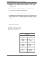
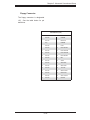
5-11 Parallel Port, Floppy, IDE and SATA Drive Connections ............................. 5-22
Parallel Port Connector .......................................................................... 5-22
Floppy Connector ................................................................................... 5-23
IDE Connectors ...................................................................................... 5-24
SATA Ports ............................................................................................. 5-24
Chapter 6: Advanced Chassis Setup
6-1
Static-Sensitive Devices ................................................................................. 6-1
6-2
Control Panel .................................................................................................. 6-2
6-3
System Fans ................................................................................................... 6-3
System Fan Failure .................................................................................. 6-3
Replacing System Fans ........................................................................... 6-3
6-4
Drive Bay Installation/Removal ....................................................................... 6-4
Accessing the Drive Bays ........................................................................ 6-4
SAS Drive Installation .............................................................................. 6-5
Installing Components in the 5.25" Drive Bays ....................................... 6-7
6-5
Power Supply ................................................................................................. 6-8
Power Supply Failure ............................................................................... 6-8
Removing/Replacing the Power Supply ................................................... 6-8
Chapter 7: BIOS
7-1
Introduction ..................................................................................................... 7-1
7-2
Running Setup ................................................................................................ 7-2
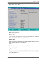
7-3
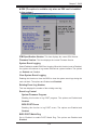
Main BIOS Setup ............................................................................................ 7-2
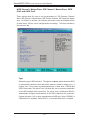
7-4
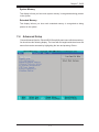
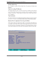
Advanced Setup ............................................................................................. 7-7
viii
Table of Contents
7-5
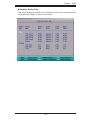
Security ......................................................................................................... 7-24
7-6
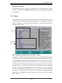
Boot .............................................................................................................. 7-25
7-7
Exit ................................................................................................................ 7-26
Appendices:
Appendix A: BIOS POST Messages
Appendix B: BIOS POST Codes
Appendix C: RAID and Software Installation
Appendix D: System Specifications
ix
Series3800/S120R-2
(6025B-3/6025B-3R)
User's Manual
Notes
x
Chapter 1: Introduction
Chapter 1
Introduction
1-1
Overview
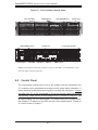
The Series3800/S120R-2 (6025B-3/6025B-3R) is a high-end server that is comprised of
two main subsystems: the SC825TQ-560LP/SC825TQ-R700LP 2U server chassis
and the X7DB3 Intel dual Xeon processor serverboard. Please refer to our web
site for information on operating systems that have been certified for use with the
Series3800/S120R-2 (6025B-3/6025B-3R).
In addition to the serverboard and chassis, various hardware components have been
included with the Series3800/S120R-2 (6025B-3/6025B-3R), as listed below:
Three (3) 8-cm hot-swap chassis fans (FAN-0094L)
One (1) DVD-ROM drive [DVM-PNSC-824V(B)]
One (1) air shroud (MCP-310-00005-00)
One (1) front control panel cable (CBL-0087)
SAS Accessories
One (1) SAS backplane (BPN-SAS-825TQ)
Two (2) SAS cables (CBL-0176L)
Eight (8) hot-swap drive carriers [MCP-220-00001-03(01)]
Two (2) CPU passive heatsinks (SNK-P0018)
One (1) rackmount kit (MCP-290-00002-00)
Note: the "V" at the end of a server name (e.g. 6025B-3V/6025B-3RV) denotes the
chassis is silver in color.
1-1
Series3800/S120R-2
1-2
(6025B-3/6025B-3R)
User's Manual
Serverboard Features
At the heart of the Series3800/S120R-2 (6025B-3/6025B-3R) lies the X7DB3, a dual
processor serverboard based on the Intel 5000P chipset and designed to provide
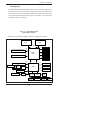
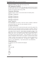
maximum performance. Below are the main features of the X7DB3. (See Figure
1-1 for a block diagram of the 5000P chipset).
Processors
The X7DB3 supports single or dual Intel dual-core Xeon 5000/5100 Sequence
processors at a FSB speed of 1333 MHz.
Memory
The X7DB3 has eight 240-pin DIMM slots that can support up to 32 GB of FBD
(Fully Buffered DIMMs) ECC DDR2-667/533 SDRAM. The memory operates in a
2-way interleaved configurations and requires requires modules of the same size
and speed to be installed in pairs (two at a time). See Section 5-5 for details.
Onboard SAS
An onboard Adaptec AIC-9410 SAS controller in integrated into the X7DB3, which
supports eight SAS hard drives. The SAS drives are connected to a backplane
that provides power, bus termination and configuration settings. The SAS drives
are hot-swappable units.
Note: The operating system you use must have RAID support to enable the
hot-swap capability and RAID function of the SAS drives. RAID 0, 1 and 10 are
supported.
PCI Expansion Slots
The X7DB3 has six PCI expansion slots, which includes two x8 PCI-Express slots,
one x4 PCI-Express slot, two 64-bit 133 MHz PCI-X slots and one 64-bit 100 MHz
PCI-X slot. The 100 MHz PCI slot supports Zero Channel RAID.
Onboard Controllers/Ports
1-2
Chapter 1: Introduction
One floppy drive controller and two onboard ATA/100 controllers are provided to
support up to four IDE hard drives or ATAPI devices. The color-coded I/O ports
include one COM port (an additional COM header is located on the serverboard), a
VGA (monitor) port, a parallel port, two USB 2.0 ports, PS/2 mouse and keyboard
ports and two gigabit Ethernet ports.
ATI Graphics Controller
The X7DB3 features an integrated ATI video controller based on the ES1000 graphics chip. The ES1000 was designed specifically for servers, featuring low power
consumption, high reliability and superior longevity.
Other Features
Other onboard features that promote system health include onboard voltage monitors, a chassis intrusion header, auto-switching voltage regulators, chassis and CPU
overheat sensors, virus protection and BIOS rescue.
1-3
Series3800/S120R-2
1-3
(6025B-3/6025B-3R)
User's Manual
Server Chassis Features
The following is a general outline of the main features of the SC825TQ-560LP/
SC825TQ-R700LP server chassis.
System Power
The SC825TQ-560LP features a single 560W power supply. The system must be
shut down and the AC power cord removed before replacing or performing any
service on the power supply unit. The SC825TQ-R700LP features a redundant
700W power supply consisting of two power modules. The system does not need
to be shut down when replacing or removing a single power supply module.
SAS Subsystem
The SC825TQ-560LP/SC825TQ-R700LP chassis was designed to support eight
SAS hard drives, which are hot-swappable units.
Note: The operating system you use must have RAID support to enable the hotswap capability of the SAS drives.
Front Control Panel
The control panel on the Series3800/S120R-2 (6025B-3/6025B-3R) provides you with
system monitoring and control. LEDs indicate system power, HDD activity, network
activity, system overheat and power failure. A main power button and a system
reset button are also included. In addition, two USB ports have been incorporated
into the control panel to provide front side USB access.
I/O Backplane
The SC825TQ-560LP/SC825TQ-R700LP is an ATX form factor chassis designed for
use in a 2U rackmount configuration. The I/O backplane provides seven low-profile
PCI expansion slots, one COM port, a parallel port, a VGA port, two USB 2.0 ports,
PS/2 mouse and keyboard ports and two gigabit Ethernet ports.
1-4
Chapter 1: Introduction
Cooling System
The SC825TQ-560LP/SC825TQ-R700LP chassis has an innovative cooling design
that includes three 8-cm hot-plug system cooling fans located in the middle section
of the chassis. An air shroud channels the airflow from the system fans to efficiently
cool the processor and onboard memory area of the system. The power supply
module also includes a cooling fan.
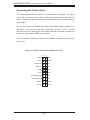
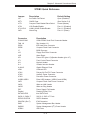
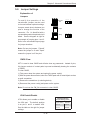
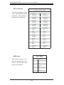
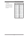
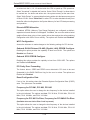
Figure 1-1. Intel 5000P Chipset:
System Block Diagram
Note: This is a general block diagram. Please see Chapter 5 for details.
CPU1
CPU2
1067/1333 MT/s
PCI-Exp
FBD CH2
x8
Slot 5: PCI-Express x8
FBD DIMM Bank4
FBD CH1
5000P
MCH
FBD DIMM Bank3
Slot 6: PCI-Exp x8/SEPC
FBD DIMM Bank2
x8
FBD DIMM Bank1
FBD CH0
PCI-Exp
PCI-Exp
3.0 Gb/s
SATA Ports (6)
PCI-Exp
ATA 100
ESB2
x8
PXH
Slot 3: PCI-X
USB 2.0
PCI-X 133
PCI 32
LAN Ports (2)
DDR2
x4
Slot 4: PCI-Express x8
AIC
Slot 2: PCI-X
9410
Slot 1: PCI-X
PCI-E x4
PCI-E x8
FBD CH3
82563
Kumeran
ATI
ES1000
Kybd/
Mouse
1-5
IDE Ports (2)
USB Ports (5)
LPC
S I/O
Floppy
BIOS
COM
Ports (2)
Parallel
Port
Series3800/S120R-2
1-4
(6025B-3/6025B-3R)
User's Manual
Notes
1-6
Chapter 2: Server Installation
Chapter 2
Server Installation
2-1 Overview
This chapter provides a quick setup checklist to get your Series3800/S120R-2
(6025B-3/6025B-3R) up and running. Following these steps in the order given
should enable you to have the system operational within a minimum amount of
time. This quick setup assumes that your system has come to you with the processors and memory preinstalled. If your system is not already fully integrated with a
serverboard, processors, system memory etc., please turn to the chapter or section
noted in each step for details on installing specific components.
2-2
Unpacking the System
You should inspect the box the Series3800/S120R-2 (6025B-3/6025B-3R) was
shipped in and note if it was damaged in any way. If the server itself shows damage you should file a damage claim with the carrier who delivered it.
Decide on a suitable location for the rack unit that will hold the Series3800/S120R-2
(6025B-3/6025B-3R). It should be situated in a clean, dust-free area that is well
ventilated. Avoid areas where heat, electrical noise and electromagnetic fields are
generated. You will also need it placed near a grounded power outlet. Read the
Rack and Server Precautions in the next section.
2-3
Preparing for Setup
The box the Series3800/S120R-2 (6025B-3/6025B-3R) was shipped in should
include two sets of rail assemblies, two rail mounting brackets and the mounting
screws you will need to install the system into the rack. Follow the steps in the order
given to complete the installation process in a minimum amount of time. Please
read this section in its entirety before you begin the installation procedure outlined
in the sections that follow.
2-1
Series3800/S120R-2
(6025B-3/6025B-3R)
User's Manual
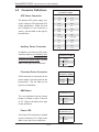
Choosing a Setup Location
- Leave enough clearance in front of the rack to enable you to open the front
door completely (~25 inches).
- Leave approximately 30 inches of clearance in the back of the rack to allow for
sufficient airflow and ease in servicing.
-This product is for installation only in a Restricted Access Location (dedicated
equipment rooms, service closets and the like).
-This product is not suitable for use with visual display work place devices acccording to §2 of the the German Ordinance for Work with Visual Display Units.
!
Warnings and Precautions!
!
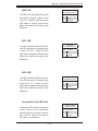
Rack Precautions
- Ensure that the leveling jacks on the bottom of the rack are fully extended to the
floor with the full weight of the rack resting on them.
- In single rack installation, stabilizers should be attached to the rack.
- In multiple rack installations, the racks should be coupled together.
- Always make sure the rack is stable before extending a component from the
rack.
- You should extend only one component at a time - extending two or more simultaneously may cause the rack to become unstable.
Server Precautions
- Review the electrical and general safety precautions in Chapter 4.
- Determine the placement of each component in the rack before you install the
rails.
- Install the heaviest server components on the bottom of the rack first, and then
work up.
- Use a regulating uninterruptible power supply (UPS) to protect the server from
power surges, voltage spikes and to keep your system operating in case of a power
failure.
- Allow the hot plug SAS drives and power supply units to cool before touching them.
- Always keep the rack's front door and all panels and components on the servers
closed when not servicing to maintain proper cooling.
2-2
Chapter 2: Server Installation
Rack Mounting Considerations
Ambient Operating Temperature
If installed in a closed or multi-unit rack assembly, the ambient operating temperature of the rack environment may be greater than the ambient temperature of the
room. Therefore, consideration should be given to installing the equipment in an
environment compatible with the manufacturer’s maximum rated ambient temperature (Tmra).
Reduced Airflow
Equipment should be mounted into a rack so that the amount of airflow required
for safe operation is not compromised.
Mechanical Loading
Equipment should be mounted into a rack so that a hazardous condition does not
arise due to uneven mechanical loading.
Circuit Overloading
Consideration should be given to the connection of the equipment to the power
supply circuitry and the effect that any possible overloading of circuits might have
on overcurrent protection and power supply wiring. Appropriate consideration of
equipment nameplate ratings should be used when addressing this concern.
Reliable Ground
A reliable ground must be maintained at all times. To ensure this, the rack itself
should be grounded. Particular attention should be given to power supply connections other than the direct connections to the branch circuit (i.e. the use of power
strips, etc.).
2-3
Series3800/S120R-2
2-4
(6025B-3/6025B-3R)
User's Manual
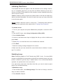
Installing the System into a Rack
This section provides information on installing the Series3800/S120R-2 (6025B3/6025B-3R) into a rack unit. If the S120R-2 has already been mounted into a
rack, you can skip ahead to Sections 2-5 and 2-6. There are a variety of rack
units on the market, which may mean the assembly procedure will differ slightly.
The following is a guideline for installing the system into a rack with the rack rails
provided. You should also refer to the installation instructions that came with the
rack unit you are using.
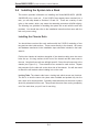
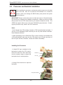
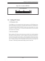
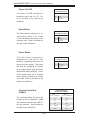
Installing the Chassis Rails
You should have received four rack sections with the S120R-2 consisting of two
long and two short rails sections. These secure directly to the chassis. All screws
and hardware mentioned in the installation steps should be included in the hardware kit.
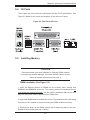
Position the chassis rail sections alongside of the chassis making sure the screw
holes line up - the long sections to the front of the chassis and the sorter ones to
the rear. Note that these rails are left/right specific. Screw the rails securely to the
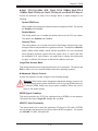
chassis (see Figure 2-1). There should be two screws for each section. Repeat
this procedure for the other rail on the other side of the chassis. You will also need
to attach the rail brackets when installng into a telco rack.
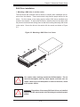
Locking Tabs: The chassis rails have a locking tab, which serves two functions.
The first is to lock the server into place when installed and pushed fully into the
rack, which is its normal position. Secondly, these tabs also lock the server in place
when fully extended from the rack. This prevents the server from coming completely
out of the rack when you pull it out for servicing.
2-4
Chapter 2: Server Installation
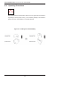
Figure 2-1. Installing Chassis Rails
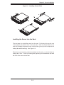
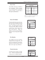
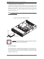
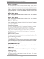
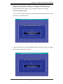
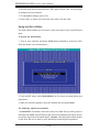
Installing the Server into the Rack
The next step is to install the server into the rack. Do this by lining up the rear
of the chassis rails with the front of the rack rails. Slide the chassis rails into the
rack rails, keeping the pressure even on both sides (you may have to depress the
locking tabs when inserting). See Figure 2-2.
When the server has been pushed completely into the rack, you should hear the
locking tabs "click". Finish by inserting and tightening the thumbscrews that hold
the front of the server to the rack.
2-5
Series3800/S120R-2
(6025B-3/6025B-3R)
User's Manual
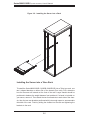
Figure 2-2. Installing the Server into a Rack
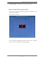
Installing the Server into a Telco Rack
To install the Series3800/S120R-2 (6025B-3/6025B-3R) into a Telco type rack, use
two L-shaped brackets on either side of the chassis (four total). First, determine
how far the server will extend out the front of the rack. Larger chassis should be
positioned to balance the weight between front and back. If a bezel is included on
your server, remove it. Then attach the two front brackets to each side of the chassis, then the two rear brackets positioned with just enough space to accommodate
the width of the rack. Finish by sliding the chassis into the rack and tightening the
brackets to the rack.
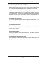
2-6
Chapter 2: Server Installation
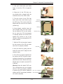
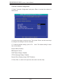
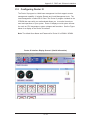
2-5
Checking the Serverboard Setup
After you install the S120R-2 in the rack, you will need to open the unit to make sure
the serverboard is properly installed and all the connections have been made.
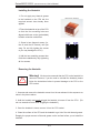
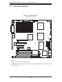
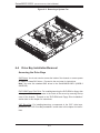
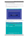
1. Accessing the inside of the System (see Figure 2-3)
First, grasp the two handles on either side and pull the unit straight out until it locks
(you will hear a "click"). Next