1
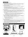
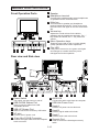
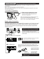
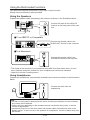
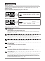
WARNING
TO PREVENT FIRE OR SHOCK HAZARDS, DO NOT EXPOSE THIS UNIT TO RAIN OR MOISTURE. ALSO, DO
NOT USE THIS UNIT’S POLARIZED PLUG WITH AN EXTENSION CORD RECEPTACLE OR OTHER OUTLETS
UNLESS THE PRONGS CAN BE FULLY INSERTED.
REFRAIN FROM OPENING THE CABINET AS THERE ARE HIGH VOLTAGE COMPONENTS INSIDE. REFER
SERVICING TO QUALIFIED SERVICE PERSONNEL.
CAUTION
CAUTION: TO REDUCE THE RISK OF ELECTRIC SHOCK, MAKE SURE POWER CORD IS UNPLUGGED
FROM WALL SOCKET. TO FULLY DISENGAGE THE POWER TO THE UNIT, PLEASE
DISCONNECT THE POWER CORD FROM THE AC OUTLET. DO NOT REMOVE COVER (OR
BACK). NO USER SERVICEABLE PARTS INSIDE. REFER SERVICING TO QUALIFIED SERVICE
PERSONNEL.
This symbol warns user that uninsulated voltage within the unit may have sufficient magnitude to cause
electric shock. Therefore, it is dangerous to make any kind of contact with any part inside this unit.
This symbol alerts the user that important literature concerning the operation and maintenance of this unit has
been included. Therefore, it should be read carefully in order to avoid any problems.
POWER CORD SELECTION
The power cord set for this unit has been packed separately and has been selected according to the country of
destination and must be used to prevent electric shock. Use the following guidelines if it is necessary to replace
the original cord set, or if the cord set is not enclosed.
The female receptacle of the cord set must meet CEE-22 requirements and will look like Figure 1:
For the United States and Canada:
In the United States and Canada the male plug is a NEMA 5-15 style (Figure 2) and is UL listed and CSA labelled.
For units which are mounted on a desk or table, type SVT or SJT cord sets may be used. For units which sit on
the floor, only SJT type cord sets may be used. The cord set must be selected according to the current rating for
your unit. Please consult Table A for the selection criteria for power cords used in the United States and Canada.
(The cord set is marked with its Cord Type.)
For European Countries:
In Europe you must use a cord set which is appropriate for the receptacles in your country. The cord set is
HAR-Certified, and the mark t HAR s will appear on the outer sheath, or on the insulation of one of the
inner conductors.
In UK, a BS approved power cord with moulded plug has a Black (five Amps) fuse installed for use with this
equipment. If a power cord is not supplied with this equipment please contact your supplier.
For all other countries:
For all other cases, use a power cord that matches the AC voltage of the power outlet and has been approved by
and complies with the safety standard of your particular country.
If you have any questions concerning the proper power cord to use, please consult with the dealer from whom
you have purchased your unit.
Table A
Cord Type
SJT
SVT
Size of Conductors In Cord
18AWG
16AWG
14AWG
18AWG
17AWG
Maximum Current Rating of Unit
10Amps
12Amps
12Amps
10Amps
12Amps
Figure 1
Figure 2
IBM PC/XT/AT, PS/2, MCGA, VGA, 8514/A and XGA are registered trademarks of International
Business Machines Corporation.
Apple and Macintosh are registered trademarks of Apple Computer Inc.
Microsoft and Windows are registered trademarks of the Microsoft Corporation.
ENERGY STAR is a U.S. registered mark.
NEC is a registered trademark of NEC Corporation. ErgoDesign and IPM are trademarks of NEC Home
Electronics, Ltd.
MultiSync is a registered trademark of NEC Technologies, Inc in U.S., and of NEC Home Electronics,
Ltd in Canada, U.K., Germany, France, Spain, Italy, Austria, Benelux, Switzerland, Denmark, Finland,
Norway and Saudi Arabia.
All other trademarks or registered trademarks are property of their respective owners.
I-1
ENGLISH
Safety Instruction
ENGLISH
K This monitor cannot be used in the interlaced mode.
K When the Apple Power Macintosh® is used, use the “On The
Fly” mode.
Please refer to the operation manuals of your computer and video cards
for further details.
As an E NERGY S TAR ® partner, NEC has determined that this product meets the
E NERGY STAR ® guidelines for energy efficiency.
NOTES:
K
For ergonomic reasons, it is recommended not to use blue characters on a dark background.
Doing so may produce insufficient contrast that could lead to eye strain.
CE Conformity
This device complies with the requirements of the EEC directive 89 / 336 / EEC as amended
by 92 / 31 / EEC and 93 / 68 / EEC Art.5 with regard to “Electromagnetic compatibility”, and
73 / 23 / EEC as amended by 93 / 68 / EEC Art. 13 with regard to “Safety”.
Required item
Relative to Standard Value Relative to those Exceeding Standard Value Remarks
EM I
#1
#4
ESD
#2
#3
RADIATED RF
#1
#3
TRANSIENT F / B
#1
#3
LINE HARMONICS
#1
#1 : Satisfies standards with no problems in performance and reliability.
#2 : Effects may appear temporarily on the screen but there will be no problem in reliability.
#3 : There is fear of the product breaking down.
#4 : If a signal cable other than that specified is used, it may be the cause of electromagnetic wave
interruption to peripheral devices.
To assure continued CE compliance the user must use the provided 1.5 m shielded video signal cable
with bonded ferrite cores at both ends of the cable.
Handle correctly in accordance with the instruction manual.
EMI : Electromagnetic Interference
ESD : Electrostatic Discharge
RF : Radio Frequency
F / B : Fast Burst
(1) Unauthorized modification of any part or the entire unit is prohibited.
(2) The contents of this manual may be modified without notice in the future.
(3) The contents of this manual may be changed for improvements but if there is any error or
omission please contact your sales representative.
(4) Please be aware in advance that in spite of the contents described in item (3), our company
is not responsible and will not assume any losses for bills for financial loss resulting from
damage caused by use of this equipment.
(5) We will make exchanges for incorrect collating or missing pages in this manual. Please
contact your sales representative.
I-2
Federal Communications Commission Requirements
This equipment has been tested and found to comply with the limits for Class B digital devices,
pursuant to Part 15 of the FCC Rules. These limits are designed to provide reasonable protection
against harmful interference in a residential installation. This equipment generates, uses, and can
radiate radio frequency energy and, if not installed and used in accordance with the instructions, may
cause harmful interference to radio communications. However, there is no guarantee that interference
will not occur in a particular installation. If this equipment does cause harmful interference to radio or
television reception, which can be determined by turning the equipment off and on, the user is
encouraged to try to correct the interference by one or more of the following measures:
– Reorient or relocate the receiving antenna.
– Increase the separation between the equipment and receiver.
– Connect the equipment into an outlet on a circuit different from that to which the receiver is connected.
– Consult the dealer or an experienced radio / TV technician for help.
FCC Warning:
To assure continued FCC compliance, the user must use grounded power supply cord and the
provided shielded video interface cable with bonded ferrite cores.
Also, any unauthorized changes or modifications to this monitor would void the users authority
to operate this device.
Customer’s Record
M The serial number (SERIAL No.) is important for quality control. Check the serial
number (SERIAL No.) on the main unit of the product and the guarantee certificate.
Read this manual carefully and use the monitor correctly.
It is convenient if the serial number of the unit is indicated in the provided space.
Model number
: LA-1524HMW
Serial number
:
Table of Contents
The product names are registered trademarks of their
respective companies.
WARNING ..............................................................................
CAUTION ...............................................................................
Recommended Use ................................................................
Dimensions .............................................................................
Features .................................................................................
Names and Functions .............................................................
Connections ............................................................................
AC Power Cord .......................................................................
On-Screen Display (OSD) ......................................................
Operation Procedures ............................................................
Adjustments ............................................................................
Power Management System ..................................................
Display Modes Memory ..........................................................
If Trouble Occurs ....................................................................
Specifications .........................................................................
Preset Modes .........................................................................
Security Port ...........................................................................
TCO’95 ...................................................................................
I-3
I-4
I-4
I-4
I-5
I-5
I-6
I-7
I-10
I-11
I-12
I-13
I-16
I-16
I-17
I-18
I-19
I-19
I-20
WARNING
• DO NOT OPEN THE MONITOR. There are no user serviceable parts inside and opening or removing
covers may expose you to dangerous shock hazards or other risks. Refer all servicing to qualified
service personnel.
• Do not damage the power cord (ex, placing any heavy objects on the power cord). The damage to
the cord may cause shock or fire.
• Do not insert objects of any kind into the cabinet slots, as they may touch dangerous voltage points, which
can be harmful or fatal or may cause electric shock, fire or equipment failure.
• Do not place this product on a sloping or unstable cart, stand or table, as the monitor may fall,
causing serious damage to the monitor, or The unit could fall or tip over and may result in injury.
• Do not spill any liquids into the cabinet or use your monitor near water, or it may result in a fire or
electric shock.
• Plug power cable completely into wall outlet and inlet lf the main unit, incomplete plugging may cause
fire or electric shock.
• Immediately unplug your monitor from the wall outlet, holding the male plug. And refer servicing to
qualified service personnel under the following conditions, or it may result in a fire or electric shock.
• When the power supply cord or plug is damaged.
• If liquid has been spilled or objects have fallen into the monitor.
• If the monitor has been exposed to rain or water.
• If the monitor has been dropped or the cabinet is damaged.
CAUTION
• Allow adequate ventilation around the monitor so that heat can properly dissipate.
Do not block ventilated openings or place the monitor near a radiator or other heat sources, Do not
spill anything on top of monitor, or it may result in a fire or electric shock.
• Do not store or use the unit in places exposed to direct sunlight or near equipment that generates
heat. It may result in fire.
Recommended Use
For optimum performance, please note the following when setting up and using the MultiSync
LCD1500M colour monitor:
•
•
•
•
•
•
•
•
•
The optimum monitor position is facing away from direct sunlight.
Use the monitor in a clean and dry area.
Handle with care when transporting. Save packaging for transporting.
The power cable connector is the primary means of detaching the system from the power supply.
The monitor should be installed close to a power outlet which is easily accessible.
The inside of the fluorescent tube located within the LCD monitor contains mercury. Please follow the
bylaws or rules of your local municipality to dispose of this tube property.
Clean the LCD monitor surface with a lint-free, non-abrasive cloth. Avoid using any cleaning solution,
glass cleaner or tissue paper.
For optimum performance, allow 30 minutes for warm-up.
Avoid displaying fixed patterns on the monitor for long periods of the time to avoid image persistence
(after-image effects.)
Avoid applying pressure to the LCD monitor surface.
CORRECT PLACEMENT AND ADJUSTMENT OF THE MONITOR CAN REDUCE EYE,
SHOULDER AND NECK FATIGUE. CHECK THE FOLLOWING WHEN YOU POSITION THE
MONITOR:
• Adjust the monitor height so that top of the screen is at or slightly below eye level.
Your eyes should look slightly downward when viewing the middle of the screen.
• Position your monitor no closer than 40 cm and no further away than 70 cm from your eyes. The
optimal distance is 53 cm for the MultiSync LCD1500M monitor.
• Rest your eyes periodically by focusing on an object at least 6 m away.
• Position the monitor at a 90° angle to windows and other light sources to minimize glare and
reflections. Adjust the monitor tilt so that ceiling lights do not reflect on your screen.
• If reflected light makes it hard for you to see your screen, use an anti-glare filter.
• Adjust the monitor’s brightness and contrast control to enhance readability.
• Use a document holder placed close to the screen.
• Position whatever you are looking at most of the time (the screen or reference material) directly in
front of you to minimize turning your head while you are typing.
• Get regular eye checkups.
I-4
Features
High-quality liquid crystal panel
• The 15 inch (0.297 mm pixel pitch) panel and anti-glare hard coating enables low reflection,
anti-static, high-resolution and high-contrast characteristics and equivalent of 16.19 million
colors display (full-color) is also possible.
• Bass-reflex type stereo speakers (1 W +1 W) are used for bass reproduction.
Plug & Play Compatible
• This unit conforms to the VESA® (Video Electronics Standards Association) DDC™ (Display Data
Channel) specified by Windows® 95 / 98.
• Any self-powered mode that conforms to USB (Universal Serial Bus) ver. 1.0 can be used.
Up to four USB-compatible devices can easily be connected.* 1
• A picture adjustment function makes it possible to adjust the image quality to match the input signal.
*1: Use is not possible in some cases, depending on the personal computer and OS used.
Digital Multi-scan
• This unit has a horizontal frequency of 30 kHz to 61 kHz, vertical frequency 50 Hz to 77 Hz with
automatic following and a maximum resolution of 1024 (H) × 768 (V) (75 Hz refresh rate).
• This unit is compatible with both IBM ® PC or compatible units and Apple Macintosh® (13" / 16" /
19" modes* 2, and the Power Macintosh® “On the Fly” mode*2).
• Use of a pixel conversion method enables clear characters and graphic display in the fullscreen*3 display.
*2: Only when the horizontal and vertical synchronization signals are input separately.
*3: In the modes from 640 × 400 to 832 × 624. However, the full-screen display may not be
possible depending on the timing or the type of computer that is used.
An automatic size adjustment function is provided.
• The input signal is determined automatically and the adjustments for the “H. POSITION”, “H.
SIZE”*4, “V. FINETUNE”*5, “ V. POSITION”, “V. SIZE”*4 and “H. FINETUNE”*5 are performed
automatically* 6 when the automatic size adjustment function is set.
*4: In the 640 × 400 to 832 × 624 modes.
*5: Only in the 1024 × 768 mode.
*6: Manual adjustment is required when the 1024 × 768 mode is used or depending on the
timing or the computer that is used.
Environmentally-friendly
• The LCD monitor power consumption can be reduced by using this unit in combination of a
computer that conforms to the VESA® DPMS™ (Display Power Management Signaling) standard.
• This product conforms to the international ENERGY STAR® program standards.
• It conforms to Sweden’s MPR II guidelines (low-frequency electro-magnetic field) and TCO’95
(emissions, power saving, ecology, ergonomics, safety) has been obtained.
• Desk space can be used effectively due to the 20.0 cm depth.
Dimensions
When adjusting the angle, hold the bottom corners of the monitor with both
hands and turn it slowly. Do not press on the upper part of the LCD as this may
cause the unit to fall down.
Dimension unit : mm
385 mm (W) × 391 mm (H) × 200 mm (D)
Angle adjustment range: 0~30° vertically
I-5
Names and Functions
Front Operation Parts
1 Speaker
2 Headphone terminal
Commercially available audio stereo headphones
or speakers can be connected here.
3 Mute key
Turns the built-in speaker and headphone
terminal sound ON and OFF. Press once to turn
the sound OFF and again to turn the sound back
ON.
4 Volume key
1
Adjusts the sound volume for the built-in
speakers and the headphone terminals. The “−”
key lowers the volume; the “+” key raises the
volume.
1
5 Menu Operation keys
These keys are used for the on-screen display
(OSD) operations and screen adjustment.
6 Pilot LED
2
4
3
5
6
If the power is turned on, the green color lights
and changes to a amber when the power
management function operates.
Rear view and Side view
7
8
9
13
10
11
12
7 Power Switch
13
Used to connect cables from USBcompatible devices.
9 USB-UP Stream Port
Used to connect the accessory USB cable.
10 AC inlet
Connect the AC power cord.
11 15 pin Mini D-SUB Connector
Connect the signal cable from the computer
to this connector.
15 17 16
8
12 AUDIO IN
This switch sets the power on and off.
8 USB-DOWN Stream Port
14
Connect the audio cable from the computer.
13 USB Hub Power Cord
14 Hook A
Hold the AC power cord to this hook.
15 Hook B
Hold the signal cable to this hook.
16 Hook C
Hold the audio cord to this hook.
17 Security Port
Used to connect the Kensington security
cable.
I-6
Connections
Always turn off the power supply of the computer and the
monitor before performing the connection procedures.
The connection method differs depending on the type of computer the monitor is
connected to.
Refer to the following page to connect the monitor.
When other types of computers are used, refer to their operation manual for the correct
connection procedures.
Connection Preparation
Cable storage compartment cover
Connect the signal cable and electrical cord
and then store the cable section that is not
used in this compartment.
Refer to the following figure in advance and remove
the cover of the cable storage compartment.
(Remove the cover while pressing the parts indicated
by the e and f arrow marks in the figure.)
Signal cable Connection
Connection method will differ in accordance with the computer in use. Connect one end of
the supplied signal cable to the mini D-SUB 15-pin connector on the rear of the unit, and
then connect the other end to the computer’s video connector. Refer to the following if
connection is to be made to any other computer, refer to the instruction manual of the
machine in question.
Tighten the screws securing the plug tightly
to prevent it from becoming disconnected.
Connect the standard connector to the video input
connector on the rear side of the monitor.
Place the signal cable to the hook on the rear side
of the monitor.
■ To an IBM PC or Compatible
Connect the standard connector to the video
output connector of the computer.
Tighten the screws securing the plug tightly
to prevent it from becoming disconnected.
■ To a Macintosh
Use the accessory signal cable and the adapter for the
Macintosh. Connect the cable as shown in the figure. When
another video card is used, read the operation manual for
that card.
Connect the Macintosh
adapter to the computer
video output connector.
Macintosh
adapter
(not included)
Connect the signal
connector to the
Macintosh adapter.
Tighten the screws on the connector or
adapter securely.
I-7
Using the Multi-media Functions
Your personal computer must have a voice input / output function.
Always use the accessory cable provided.
Using the Speakers
Prepare the speaker cable (accessory) and connect as shown in the illustration below.
Connect the cable to the AUDIO IN
terminal on the back panel of the main
unit.
■ To an IBM PC or Compatible
Connect the speaker cable to the
AUDIO OUT terminal of the computer.
■ To a Macintosh
Connect the speaker cable to the
SPEAKER terminal of the computer.
* The shape of the terminal of your computer may differ from that shown here. In such
case, read the instruction manual for your computer and connect as indicated.
* Lower the volume if howling occurs.
Using Headphones
Prepare the headphones (commercially available) and connect as shown in the illustration
below.
Connect the cable from the
headphones.
Note:
• If a filter or touch panel is attached to the screen, blocking the speakers, the sound quality
and volume will be affected.
• Volume will vary depending on the headphones and microphone being used, so set the
volume as appropriate.
• Interference may occur if the micro-cable and speaker cable are positioned close to the
display monitor. If noise occurs in the speakers or headphones, move the cables away from
the monitor.
I-8
Connecting USB Devices
Always use the USB cord that is enclosed with the
unit.
1 Prepare the accessory USB cord provided.
2 Connect the USB connector (Type A) to the computer.
3 Connect the USB connector (Type B) to the USB Upstream port of the main unit.
4 Connect the cord of the USB device being used to the USB Downstream port of the
main unit.
■ USB Cord
Type A Connector
Type B Connector
■ Typical Connections
Computer
Connect the accessory
USB cord.
Right side panel
Rear panel
Left side panel
Connect the accessory
USB cord.
Connect the cord from the USB peripheral device.
Mouse
Keyboard
I-9
Printer
Always use the power supply cord that is enclosed with
the unit.
AC Power Cord
If the enclosed power supply cord is not used, use a power cord that conforms to the following
regional standards.
U.S.A. .................. UL
Switzerland .......... SEV
Canada ................ CSA
Britain ................... BASEC / BS
Germany .............. VDE
In other regions, for safety please use an AC plug cord that complies with each country’s safety
regulations.
Power Cord Connection
Always use the accessory power cord and be sure to
connect the ground line.
1 Use the accessory AC power cord.
2 Connect the AC plug (female pins) to the main unit.
3 Connect the AC plug (male pins) to the electrical outlet.
Caution: Always connect the ground wire.
4 Attach the cord compartment cover.
4
2
3
1
Turn on the Power
Figure 2
Figure 1
Place the monitor where it will be used.
Use a power source that supplies AC 100 V - 240 V at 50 Hz / 60 Hz. Turn on the
power switch of the display panel (Figure 1: Press the switch continuously until the
pilot LED lights.) and then turn on the computer power switch (Figure 2).
** Refer to the section “Operation Procedures” on page I-12. Use the desired setting.
I - 10
On-Screen Display (OSD)
The meaning of the items displayed in the
on-screen display are described below.
− and + keys
Mute and Volume key
These keys set the level of the adjustment
items. Direct operation: These keys perform
the screen display contrast and other
adjustments.
Adjusts the sound volume for the built-in
speakers and the headphone terminals.
MENU key
v and ukeys
This key turns the menu screen on and off.
These keys select the adjustment items by shifting
the selection mark “s” on the menu screen.
Direct operation: These keys perform the screen
display brightness and other adjustments.
Direct Screen
There are three adjustments, contrast and brightness and mute and volume on the direct
screen.
Adjustment item icon
Adjustment level display
The adjustment items are
displayed by icons.
The adjustment level is
indicated by both a
numeric value and a bar.
Adjustment item name
Sound OSD
(When the resolution is set 1024 × 768.)
The menu screen displays icons for the adjustment items of this unit.
However, brightness level 1 cannot be adjusted on the menu screen.
Menu Screen
Adjustment icon
Selection mark
The adjustment items are
displayed as icons.
This mark is displayed on
the left side of the
selected function icon.
Adjustment level display
The adjustment level is
shown by both a numeric
value and a bar.
Adjustment item name
The selected function on the menu
screen is displayed.
I - 11
Operation Procedures
Refer to the figures below to perform
adjustments in the on-screen display.
Auto size adjustment
1. Press the MENU key to display the main menu.
2. Press the menu operation keys (v and u) to shift the “s” mark on the menu
screen to the auto size (
) adjustment.
3. Use the menu operation key (+ key) to select ON. Auto size adjustment will start
operating.
4. If the settings on the screen are satisfactory, press the MENU key to record the
settings and exit.
5. If the settings on the screen are not satisfactory, manually re-adjust where necessary.
I - 12
Adjustments
Menu Screen
The menu screen changes to two different screens according to the screen resolution.
The menu screen is displayed by the MENU key. The adjustment items of this unit are
displayed as icons.
Each icon indicates an adjustment item shown in the figure.
When the resolution is 640 × 400 to 832 × 624
CONTRAST
V. SIZE
BACKLIGHT
H. POSITION
COLOR TEMP VIDEO LEVEL ADJ
H. SIZE
V. POSITION
DISP. FREQ
LANGUAGE
AUTO SIZE
RECALL
OSD POSITION
PICTURE
CONTRAST
BACKLIGHT
H. POSITION
V. FINETUNE
V. POSITION
DISP. FREQ
LANGUAGE
When the resolution is 1024 × 768
H. FINETUNE
COLOR TEMP VIDEO LEVEL ADJ
AUTO SIZE
RECALL
OSD POSITION
PICTURE
Adjustment Item Screen
CONTRAST
Adjust the screen contrast. (Standard level = 100)
Press the MENU key to register the setting value.
Direct operation: Even if the menu screen does not appear, the contrast can be adjusted by
pressing the “+” or “−” keys.
BRIGHTNESS (Black level)
Adjust the brightness (low gradation part: black level). (Standard level = 50)
Direct operation: Even if the menu screen does not appear, the brightness can be adjusted
by pressing the “v” or “u” keys. Press the MENU key to register the setting value.
BACKLIGHT
Adjust the brightness of the backlight. (Standard level = 100)
H. POSITION
The horizontal position of the image can be adjusted.
H. SIZE
*Adjustment items when the resolution is set from 640 × 400 to 832 × 624.
The horizontal amplitude of the image can be adjusted.
After aligning the left edge of the image by the horizontal position adjustment, change to the
horizontal size adjustment and perform the adjustment by the “+” or “−” key.
V. FINETUNE
*Adjustment items when the resolution is 1024 × 768.
When the 1024 × 768 screen resolution is used, vertical stripes may be observed depending
on the desktop patterns or applications. If this occurs, perform the following adjustments.
Display a screen which has vertical stripes and align the right side of the screen by the
horizontal position adjustment, then change to the vertical stripe adjustment (V. FINETUNE)
and perform the adjustment using the “+” or “−” key.
I - 13
Adjustment Item Screen
V. POSITION
The vertical position of the image can be adjusted.
V. SIZE
*Adjustment items when the resolution is set from 640 × 400 to 832 × 624.
The vertical size of the image can be adjusted.
After aligning the top edge of the image by the vertical position adjustment, change to the
vertical size adjustment and perform the adjustment by the “+” or “−” key.
However, the optimal adjustment cannot be performed in all operation modes.
H. FINETUNE
*Adjustment items when the resolution is 1024 × 768.
When the 1024 × 768 screen resolution is used, characters may flicker or horizontal stripes
may appear depending on the desktop patterns or applications. If this occurs, perform the
following adjustments.
Display a screen which has horizontal stripes and align the bottom of the screen by the
vertical position adjustment, then change to the horizontal stripe adjustment (H. FINETUNE)
and perform the adjustment using the “+” or “−” key.
Note) There are more than two optimal points. One dot on the right or left may disappear
depending on the optimal point. If this occurs, shift to the other optimal point and
perform the horizontal position adjustment and the V. FINETUNE adjustment again.
COLOR TEMP
The white in the image can be selected from the three conditions, 1 (Normal color), 2 (9300K)
and 3 (User color: ADJ).
Use the “+” or “−” key to select the user’s preferred color from 1 (Normal color), 2 (9300K)
and 3 (User color: ADJ).
USER COLOR
The white in the video image can be adjusted to the user’s preferred color.
Select USER COLOR: [ < 3 > ADJ ] with the “+” or “−” keys on the COLOR TEMPERATURE
screen.
Select (ADJ) with the “+” key. Use the “v” or “u” keys to select R (red), G (green) or B (blue).
Use the “+” and “−” keys to adjust the color as desired.
Note: Make a note of the setting values before performing the adjustment because the
recall operation cannot be performed for the user color adjustment. The initial value is
set to normal color.
VIDEO LEVEL ADJ
The video input signal level of your computer is adjusted automatically to 0.7 V ~ 1.0 V.
Automatic adjustment is performed when ON is selected with the “+” key.
Adjustment time is about 2 ~ 3 sec.
Note) For this function to operate correctly, a white area about the size of the mouse
cursor is necessary. Correct adjustment is not possible without such a white area.
DISP. FREQ
This displays the screen mode input on the LCD monitor.
The horizontal and vertical synchronization frequency are displayed.
The values for horizontal and vertical synchronization frequency of the video signal that is
currently input for the computer are displayed.
fH: There is an error of approximately 0.2 kHz max. for 30 kHz and 0.4 kHz max. for 61 kHz.
LANGUAGE
Select one of the languages (German, French, English, Italian or Spanish) for the on-screen
display.
DEU: German
FRA: French
ENG: English
ITA : Italian
ESP: Spanish
I - 14
Adjustment Item Screen
AUTO SIZE
The following adjustment items are automatically performed for the signal input from the computer.
The horizontal position adjustment, horizontal size adjustment, vertical position adjustment,
vertical size adjustment, vertical fine adjustment (V. FINETUNE) and horizontal fine
adjustment (H. FINETUNE) .
Effective adjustment can be performed if this function is used.
• Always operate the unit after the computer has started.
• Perform the adjustment after the Windows screen or other similar screen is displayed
in the entire screen.
• Do not use this function when the VGA350 mode and DOS prompt mode are used
because the function will not operate correctly. Perform the adjustment manually.
RECALL
The initial settings (the settings when the display panel was shipped from the factory) can be
returned for each selection item.
The recall operation for the items to be reset is performed as follows.
The horizontal position adjustment, horizontal size adjustment, vertical position adjustment,
vertical size adjustment, horizontal fine adjustment (H. FINETUNE), vertical fine adjustment
(V. FINETUNE).
Press the “+” [YES] key to set an item and then press the MENU key.
Note: The recall screen display stops if there is no operation within approximately 30 seconds.
OSD POSITION
It is possible to adjust the position that the on-screen panel is to be displayed.
Moves each time the “+” or “−” key is pressed.
PICTURE
Image quality can be set to four different modes to match the type of input.
1) OFFICE MODE
Lowers the brightness when the monitor is to be used for an extended time.
2) STANDARD MODE
The factory setting.
3) DYNAMIC MODE
Emphasizes the outlines of images to make them sharper and easier to view.
4) ENTERTAINMENT MODE
Emphasizes the outlines of images even more than the Dynamic mode.
Note: The quality of text deteriorates when the Entertainment or Dynamic Mode is set.
VOLUME
This adjustment is performed directly from the front panel operation key.
key is pressed, the volume is lowered.
key is pressed, the volume is raised.
key is pressed, the volume is muted.
SIGNAL ERROR and NO SIGNAL (Monitor Self-Test)
This function displays if the main unit is operating correctly.
Figure A or B is displayed if any of the five menu operation keys (MENU, v, u, −, +) are
pressed.
1) Figure A is displayed when the input synchronization signal exceeds the specified range.
• The frequency is displayed in red when fH or fV exceed the specified range.
2) Figure B is displayed when the power save mode is set. (This figure is only displayed in
the off state.)
3) Figure B is displayed when there is no input signal.
For example, this occurs when the computer is not connected or the computer power is off.
Figure A
Figure B
I - 15
Power Management System
This monitor conforms to the VESA DPMS standard.
This function can suppress power consumption for the display unit.
The computer and video board being used must also conform to the VESA DPMS standard.
Note: Regarding operation, please consult the Operation Manuals for the hardware being used.
Modes change in response to input signals as indicated in the table below.
APM state
Screen status LED color
Power
Return time
consumption
ON STATE
Active
Green
Normal
–
STAND-BY
Black out
Amber
< 15 Watts
<
4 sec.
SUSPEND
Black out
Amber
< 15 Watts
<
4 sec.
OFF STATE
Black out
Amber
< 5 Watts
< 5 sec.
Input signal
Video
Horizontal
Vertical
ON
ON
ON
OFF
OFF
ON
OFF
ON
OFF
OFF
OFF
OFF
* No USB peripherals
APM : Advanced Power Management
Caution
• Turn the monitor off when it is not to be used for a long time.
• How to release the system from the power management function
1) Read the Operation Manuals for the hardware you are using.
2) Press one of the MENU, v, u, −, + keys on the front panel.
The No Signal screen appears, and the monitor side power management function is released
(only in OFF STATE).
* Approximately 5 seconds is required to return to ON from the OFF state.
Display Modes Memory
• Up to 16 modes can be newly registered as user’s preset modes.
• If the new adjustment data differ from any of the following 4, they can be registered as new data.
Horizontal frequency
Horizontal sync. polarity
Total number of vertical lines
Vertical sync. polarity
* It is necessary, however, that the horizontal frequency be 30 kHz ±0.2 kHz to 61 kHz ±0.4
kHz and that the difference in the number of vertical lines be ±4 lines or more.
• The data that can be registered are those in the following table.
Total number of
vertical lines
Horizontal synchronization
polarity
Vertical synchronization
polarity
Video signal level
V. FINETUNE
Horizontal frequency
Horizontal size
Horizontal position
Vertical size
Vertical position
H. FINETUNE
PICTURE
• How to register adjustment data
1) Input the computer signal to be registered to the display unit.
2) Select the item to be adjusted from the OSD screen and then adjust it.
3) When the MENU key is pressed, the adjusted value is registered.
If a front panel key is not operated for about 20 seconds, the adjustment is registered.
• There are 16 modes that can be preset by the user; if all 16 modes have already been registered,
when the one that has been registered the oldest is deleted a new mode can be registered.
• If the timing of the new registration differs little in frequency from the previously registered timing
and in addition the signal polarity is the same, they will be judged to be the same and the new
timing cannot be registered.
I - 16
If Trouble Occurs
If problems continue even after the inspections described below are performed, always remove the
power plug and contact our dealer.
Please observe the following points to ensure safety.
Symptom
The pilot LED does not
light.
There is no image.
The pilot LED does not
go off.
Check
Remedy
Reference
Page
Power cord / plug
Power switch
Signal cable
Computer (The power
saving function might have
operated. If this
occurred, the pilot LED will
be light amber.)
Contrast, brightness and
backlight adjustment
Power switch
Plug the power cord into the outlet correctly.
Press the power switch.
Connect the signal cable correctly.
Release the power saving function. (Operate
the mouse or keyboard. For additional details
please read the operation manual of the
hardware that is used.)
I-10
Adjust the contrast, brightness and backlight
correctly.
Press the power switch one more time.
I-13
Is not the mode
registered?
Is the mode guaranteed?
Use an on-screen function to perform the
desired settings.
Read the computer operation manual and
change the display mode to obtain the
specified mode.
I-12
Perform the V. FINETUNE
(Vertical stripe), H.
FINETUNE (Horizontal
stripe) adjustments (In the
1024 × 768 mode.)
When the 1024 × 768 mode is set, perform
I-13 ~ 14
the adjustment so the stripe patterns are not
conspicuous.
Change the desktop pattern in modes other
than 1024 × 768.
If the same screen is displayed on the
LCD display panel for a long period of time, a
phenomenon called “burn-in” may occur
where slight traces of the burned-in screen
pattern can still be observed when other
screen patterns are displayed.
Do not operate the display for approximately
one day and do not turn the power on.
The image is too large or
too small. It is displaced
from the correct position.
Part of the screen is
missing.
The color of part of the
screen is changed.
There are vertical or
horizontal stripes in the
Liquid Crystal panel
screen.
There is an after-image in
the screen.
H. FINETUNE (Horizontal
stripe) adjustments
Perform the necessary adjustments until the
characters displayed on the screen do not
flicker.
Does the video clock
Lower the vertical frequency of the image
Characters cannot be
frequency of the image
signal to set the video clock frequency to a
seen clearly even after an signal exceed the standard level below the standard level (80 MHz).
adjustment is performed. level (80 MHz)?
Has the Office mode been Set the Standard mode.
set?
Is the video level correctly Check the video signal level from the computer
adjusted?
and adjust it in the correct direction.
The outlines of text are
Is
the
brightness
or
Adjust the brightness, backlight and contrast.
sharp.
contrast adjustment turned (Refer to the computer operation manual of
all the way down?
the computer that is used for further details.)
Has the Dynamic or Enter- Set the Standard mode.
tainment mode been set?
SELF-TEST function
Signal cable
The image is too dark.
The image scrolls
continuously.
Press the MENU key to check the Self-Test
screen.
Is either one of the numeric values for fH or
fV displayed in red?
The input signal frequency exceeds the range
of the security range of this unit.
Read the operation manual of the computer
and change the display mode.
I - 17
I-7
I-16
I-10
I-19
I-14
I-15
I-14
I-13
I-15
I-15
I-14
I-19
If Trouble Occurs
Symptom
Check
Remedy
The display color is
abnormal.
Signal cable
The screen size and
position do not change.
Is the input synchronization Check the video output mode from the
signal within the
computer and select a mode within the LCD
operating range?
monitor operating range. (For details, read
the operation manual of the hardware you are
using.)
Are two or more keys
Operate only one key at a time.
being operated at the
same time?
The front panel keys fail
to operate.
Reference
Page
Connect the signal cable correctly.
I-7
I-19
The sound is not correct.
AUDIO cord
Computer sound level
Connect the AUDIO cord correctly. Is the
sound level from the computer restricted?
Please refer to the operation manual for the
hardware you are using for the details.
I-8
The headphones do not
operate.
Headphone jack
Connect the headphone jack correctly.
I-8
Connect the USB cord correctly.
For details, read the operation manual of the
USB device you are using.
I-9
The USB device does not USB cord
operate.
USB hub power cord
Specifications
Specifications are subject to change without notice for the
purpose of improvement.
LCD
Size
15 inch (15.0 inches / 38.1 cm viewable)
Type
Color TFT active matrix Liquid Crystal
Pixel pitch
Surface treatment
0.297 mm
Anti-glare, anti-static (Anti-glare hard coat)
Angle of visibility
R / L: + / – 70°, Up: 50°, Down: 70° (typ.)
Video signal
Signal level
RGB analog
0.7 Vp-p ~ 1.0 Vp-p
Synchronization
Operation Range
H / V separate (TTL level), H / V composite (TTL level), Sync-on-green
Horizontal Frequency Range: 30.0 kHz to 61.0 kHz
Input signal
Vertical Frequency Range: 50.0 Hz to 77.0 Hz
Connectors
Signal
Headphone terminals
15 pin mini D-Sub connector (female pins)
3.5 mm diameter stereo mini jack
Audio input terminal
USB terminals
3.5 mm diameter stereo mini jack
Upstream Port × 1
Power supply
Operation Keys
CEE22 type 3 pin connector
Power ON / OFF, MENU, v, u, -, + key, volume key, mute key
On-Screen Display
Maximum pixel clock
CONTRAST, BRIGHTNESS, BACKLIGHT, H. POSITION, H. SIZE,
V. FINETUNE, V. POSITION, V. SIZE, H. FINETUNE, COLOR TEMP. ( Normal
color / 9300K / User color ), VIDEO LEVEL ADJ (0.7 V ~ 1.0 V), DISP. FREQ.,
LANGUAGE, AUTO SIZE, RECALL, OSD POSITION, PICTURE, VOLUME
80 MHz (max.)
Maximum resolution
1,024 dots (H) × 768 lines (V) / 75 Hz
Display area
Speakers
304 × 228 mm (1,024 × 768)
80 Hz to 20 kHz (typ.)
Downstream Port × 4
Controls
Frequency respose
Practical audio output
Operating conditions
1.0 W + 1.0 W (typ.)
Temperature: 0 to 35°C (32 to 95°F)
Humidity: 5 to 90% (No condensation)
Input power
AC 100 – 240 V (50 / 60 Hz)
Power consumption (No USB peripherals)
Dimensions: width × height × depth
55 W typ / < 5 W (during power saving operation)
385 × 391 × 200 mm
Weight (main unit only)
Screen angle adjustment
7.1 kg
0 – 30° (Up)
I - 18
Preset Mode
Mode
Resolution
The 15 timings in the following table have been preset.
Horizontal
frequency
(kHz)
Vertical
frequency
(Hz)
Synchronization signal polarity
Horizontal
Vertical
VGA 480 at 60 Hz
VGA 400 at 70 Hz
640 × 480
640 × 400
31.47
31.47
59.94
70.08
–
–
–
+
640 × 480 at 72 Hz
640 × 480
37.86
72.81
–
–
640 × 480 at 67 Hz
640 × 480 at 75 Hz
640 × 480
640 × 480
35.00
37.50
66.67
75.00
–
–
–
–
800 × 600 at 56 Hz
800 × 600 at 60 Hz
800 × 600
800 × 600
35.16
37.88
56.25
60.32
+
+
+
+
800 × 600 at 75 Hz
800 × 600
46.88
75.00
+
+
800 × 600 at 72 Hz
832 × 624 at 75 Hz
800 × 600
832 × 624
48.08
49.73
72.19
74.55
+
–
+
–
1024 × 768 at 60 Hz
1024 × 768 at 70 Hz
1024 × 768
1024 × 768
48.36
56.48
60.00
70.07
–
–
–
–
1024 × 768 at 72 Hz
1024 × 768
57.87
71.80
–
–
1024 × 768 at 75 Hz
1024 × 768 at 75 Hz
1024 × 768
1024 × 768
60.02
60.24
75.03
74.93
+
–
+
–
Security Port
A security port can be installed to prevent theft of the LCD monitor and main unit.
A wire cable manufactured by Kensington can be connected to the security port on the
rear panel of the main unit.
For details, please refer to the Kensington instruction manual.
< Inquiries>
Kensington
2855 Campus Drive
San Mateo, CA USA 94403
800-535-4242, x3348
Intrl: 415-572-2700, x3348
Fax: 415-572-9675
I - 19
TCO’95
Congratulations! You have just purchased a TCO’95 approved and
labelled product! Your choice has provided you with a product developed
for professional use. Your purchase has also contributed to reducing
the burden on the environment and also, to the further development of
environmentally adapted electronics products.
Why do we have environmentally labelled computers?
In many countries, environmental labelling has become an established method for encouraging the
adaptation of goods and services to the environment. The main problem, as far as computers and other
electronics equipment are concerned, is that environmentally harmful substances are used both in the
products and during the manufacturing. Since it has not been possible for the majority of electronics
equipment to be recycled in a satisfactory way, most of these potentially damaging substances sooner
or later enter Nature.
There are also other characteristics of a computer, such as energy consumption levels, that are important
from the viewpoints of both the work (internal) and natural (external) environments. Since all methods
of conventional electricity generation have a negative effect on the environment (acidic and climateinfluencing emissions, radioactive waste, etc.), it is vital to conserve energy. Electronics equipment in
offices consume an enormous amount of energy since they are often left running continuously.
What does labelling involve?
This product meets the requirements for the TCO’95 scheme which provides for international and
environmental labelling of personal computers. The labelling scheme was developed as a joint effort
by the TCO (The Swedish Confederation of Professional Employees), Naturskyddsforeningen (The
Swedish Society for Nature Conservation) and NUTEK (The National Board for Industrial and Technical
Development in Sweden).
The requirements cover a wide range of issues: environment, ergonomics, usability, emission of electrical
and magnetic fields, energy consumption and electrical and fire safety.
The environmental demands concern restrictions on the presence and use of heavy metals, brominated
and chlorinated flame retardants, CFCs (freons) and chlorinated solvents, among other things. The
product must be prepared for recycling and the manufacturer is obliged to have an environmental plan
which must be adhered to in each country where the company implements its operational policy.
The energy requirements include a demand that the computer and/or display, after a certain period of
inactivity, shall reduce its power consumption to a lower level in one or more stages. The length of
time to reactivate the computer shall be reasonable for the user.
Labelled products must meet strict environmental demands, for example, in respect of the reduction of
electric and magnetic fields, physical and visual ergonomics and good usability.
On the back page of this folder, you will find a brief summary of the environmental requirements met
by this product. The complete environmental criteria document may be ordered from:
TCO Development Unit
S-114 94 Stockholm
Sweden
Fax: +46 8 782 92 07
Email (Internet): [email protected]
Current information regarding TCO’95 approved and labelled products may also be obtained via the
Internet, using the address:
http://www.tco-info.com/
TCO’95 is a co-operative project between TCO (The Swedish Confederation of Professional
Employees), Naturskyddsforeningen (The Swedish Society for Nature Conservation) and NUTEK
(The National Board for Industrial and Technical Development in Sweden).
I - 20
Environmental Requirements
Brominated flame retardants
Brominated flame retardants are present in printed circuit boards, cables, wires, casings and housings. In
turn, they delay the spread of fire. Up to thirty percent of the plastic in a computer casing can consist of
flame retardant substances. These are related to another group of environmental toxins, PCBs, which are
suspected to give rise to similar harm, including reproductive damage in fisheating birds and mammals,
due to the bio-accumulative* processes. Flame retardants have been found in human blood and researchers
fear that disturbances in foetus development may occur.
TCO’95 demand requires that plastic components weighing more than 25 grams must not contain
organically bound chlorine and bromine.
Lead**
Lead can be found in picture tubes, display screens, solders and capacitors. Lead damages the nervous
system and in higher doses, causes lead poisoning.
TCO’95 requirement permits the inclusion of lead since no replacement has yet been developed.
Cadmium**
Cadmium is present in rechargeable batteries and in the colour generating layers of certain computer
displays. Cadmium damages the nervous system and is toxic in high doses.
TCO’95 requirement states that batteries may not contain more than 25 ppm (parts per million) of
cadmium. The colour-generating layers of display screens must not contain any cadmium.
Mercury**
Mercury is sometimes found in batteries, relays and switches and back-light system. Mercury damages
the nervous system and is toxic in high doses.
TCO’95 requirement states that batteries may not contain more than 25 ppm (parts per million) of
mercury. It also demands that no mercury is present in any of the electrical or electronics components
concerned with the display unit except the back-light system.
CFCs (freons)
CFCs (freons) are sometimes used for washing printed circuit boards and in the manufacturing of
expanded foam for packaging. CFCs break down ozone and thereby damage the ozone layer in the
stratosphere, causing increased reception on Earth of ultraviolet light with consequent increased risks
of skin cancer (malignant melanoma).
The relevant TCO’95 requirement: Neither CFCs nor HCFCs may be used during the manufacturing
of the product or its packaging.
* Bio-accumulative is defined as substances which accumulate within living organisms.
** Lead, Cadmium and Mercury are heavy metals which are Bio-accumulative.
I - 21