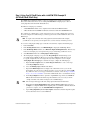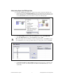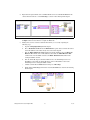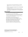
1
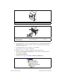
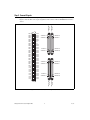
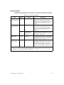
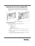
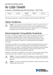
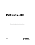
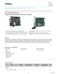
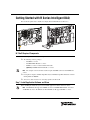
Getting Started with R Series Intelligent DAQ
This document explains how to install and configure National Instruments 78xxR devices.
Figure 1. PCI and PXI R Series Devices
NI 78xxR Required Components
The following items are necessary to set up and use the NI PCI/PXI-78xxR:
❑ The following software packages:
–
LabVIEW 7.1 or later
–
LabVIEW FPGA Module 1.1 or later
–
NI-RIO 1.3 or later—included with the NI 78xxR
–
(Optional) LabVIEW Real-Time Module 7.1 or later
Note
The examples referenced in this document require LabVIEW 8.0 or later and NI-RIO 2.0
or later.
❑ Development computer or PXI/CompactPCI chassis and PXI/CompactPCI embedded controller
running Windows 2000/XP.
❑ At least one cable and device for connecting signals to the NI 78xxR.
Step 1. Install Application Software and Driver
Before installing the NI 78xxR, you need to install the application software and device driver.
Note
The NI PXI-7831R supports LabVIEW 7.0 or later, LabVIEW FPGA Module 1.0 or later,
and NI-RIO 1.0 or later. The NI PCI-7831R and NI PXI-7811R support NI-RIO 1.1 or later.
Refer to the LabVIEW Release Notes for installation instructions for LabVIEW and system requirements
for the LabVIEW software. Refer to the LabVIEW Upgrade Notes for additional information about
upgrading to the most recent version of LabVIEW for Windows.
Refer to the LabVIEW FPGA Module Release and Upgrade Notes for installation instructions and
information on getting started with the LabVIEW FPGA Module.
Refer to the LabVIEW Real-Time Module Release and Upgrade Notes for system requirements,
installation instructions, and additional information on using the LabVIEW Real-Time Module.
The previous documents are available at ni.com/manuals or by selecting Start»All Programs»
National Instruments»LabVIEW»LabVIEW Manuals.
Step 2. Install the Device, Accessories, and Cables
This section describes how to unpack and install the NI PXI-78xxR and NI PCI-78xxR devices.
Note
You must install NI-RIO before installing the NI 78xxR.
Unpacking
The NI 78xxR is shipped in an antistatic package to prevent electrostatic discharge from damaging
device components. To prevent such damage when handling the device, take the following precautions:
•
Ground yourself using a grounding strap or by holding a grounded object, such as your computer
chassis.
•
Touch the antistatic package to a metal part of the computer chassis before removing the device
from the package.
Caution
Never touch the exposed pins of connectors.
Remove the device from the package and inspect the devices for loose components or any other sign of
damage. Notify NI if the device appears damaged in any way. Do not install a damaged device into the
computer.
Store the NI 78xxR in the antistatic envelope when not in use.
NI 78xxR Installation
You can install the NI PCI-78xxR in any available PCI expansion slot in the computer, and the
NI PXI-78xxR in any available peripheral slot in the PXI or CompactPCI chassis. To achieve the best
noise performance, leave as much room as possible between the NI PCI-78xxR and other boards.
Note You must install the software before installing the hardware. For software installation
information, refer to the Step 1. Install Application Software and Driver section.
1.
Power off and unplug the computer or PXI chassis.
Caution
Refer to the Read Me First: Safety and Radio-Frequency Interference document packaged
with your PXI chassis or device before removing equipment covers or connecting or disconnecting
any signal wires.
2.
Remove the computer cover and/or the expansion slot cover on the computer, or the filler panel of
an unused PXI slot on the PXI chassis.
3.
Touch any metal part of the computer or chassis to discharge any static electricity.
4.
For the NI PCI-78xxR, insert the device into the applicable PCI system slot on your computer.
Gently rock the device into place. Do not force the device into place. For the NI PXI-78xxR,
insert the device into the PXI slot. Use the injector/ejector handle to fully inject the NI PXI-78xxR
into place.
Getting Started with R Series Intelligent DAQ
2
ni.com
3
1
2
1
NI PCI-78xxR Device
3
PCI System Slot
3
PC with PCI Slot
Figure 2. Installing an NI PCI-78xxR Device
1
PX
I-1
000B
2
7
3
6
5
4
1
2
3
PXI Chassis
PXI System Controller
NI PXI-78xxR Device
4
5
Injector/Ejector Handle
Front-Panel Mounting Screws
6
7
Module Guides
Power Switch
Figure 3. Installing an NI PXI-78xxR Device in a PXI Chassis
5.
For the NI PCI-78xxR, secure the device mounting bracket to the computer back panel rail. For the
NI PXI-78xxR, secure the device front panel to the chassis front panel mounting rail using the
front-panel mounting screws.
6.
For the NI PCI-78xxR, replace the computer cover, if applicable.
7.
Plug in and power on the computer or PXI chassis.
To confirm that your device is recognized, complete the following additional steps:
1.
Double-click the Measurement & Automation icon on the desktop to open Measurement &
Automation Explorer (MAX).
2.
Expand Devices and Interfaces.
3.
Verify that the device appears under Devices and Interfaces»RIO Devices.
© National Instruments Corporation
3
Getting Started with R Series Intelligent DAQ
Step 3. Connect Signals
68 34
DIO38
DIO36
DIO35
67 33
66 32
DIO33
65 31
DIO31
DIO29
64 30
63 29
DIO34
DIO32
DIO30
DIO28
DIO27
62 28
+5V
DIO26
61 27
60 26
59 25
+5V
58 24
57 23
56 22
DGND
DIO25
DIO24
DIO23
DIO22
DIO21
DIO20
DIO19
DIO18
DIO17
DIO16
DIO15
DIO14
DIO13
DIO12
DIO11
DIO10
DIO9
DIO8
DIO7
DIO6
DIO5
DIO4
DIO3
DIO2
DIO1
52 18
51 17
50 16
49 15
48 14
47 13
46 12
45 11
44 10
43
42
41
9
8
7
40
39
38
6
5
4
37
36
35
3
2
1
TERMINAL 35
TERMINAL 34
TERMINAL 1
DGND
TERMINAL 1
TERMINAL 34
DGND
DGND
DGND
TERMINAL 35
TERMINAL 68
TERMINAL 68
TERMINAL 35
TERMINAL 34
TERMINAL 1
TERMINAL 1
TERMINAL 34
TERMINAL 35
TERMINAL 68
DGND
DGND
DGND
DGND
DGND
DGND
DGND
DGND
DGND
DGND
DGND
DGND
DGND
DGND
DGND
DGND
DGND
DGND
DGND
DGND
DGND
CONNECTOR 1
(RDIO)
DIO0
55 21
54 20
53 19
TERMINAL 68
CONNECTOR 2
(RDIO)
DIO39
DIO37
CONNECTOR 3
(RDIO)
CONNECTOR 0
(RDIO)
Figure 4 shows the I/O connector pin assignments and locations for NI 781xR Digital R Series devices.
Figure 5 shows the I/O connector pin assignments and locations for NI 78xxR Multifunction R Series
devices.
Figure 4. NI 781xR Connector Pin Assignments and Locations
Getting Started with R Series Intelligent DAQ
4
ni.com
CONNECTOR 0
(RMIO)
68 34
DIO35
66 32
65 31
DIO33
67 33
DIO38
DIO36
DIO34
DIO32
DIO30
DIO28
+5V
DIO31
DIO29
DIO27
64 30
DIO26
61 27
DIO25
DIO24
DIO23
60 26
59 25
+5V
DGND
DGND
58 24
DGND
DIO22
57 23
56 22
DGND
DIO21
DIO20
DIO19
DIO18
DIO17
DIO16
DIO15
DIO14
DIO13
DIO12
DIO11
DIO10
DIO9
63 29
62 28
55 21
54 20
53 19
52 18
51 17
50 16
49 15
48 14
47 13
46 12
45 11
44 10
43
42
41
9
8
7
40
39
6
5
DIO3
DIO2
DIO1
38
37
36
4
3
2
DIO0
35
1
DIO8
68 34
67 33
AI0–
AIGND1
AI1+
66 32
AI1–
AI2+
AIGND2
AI3+
65 31
64 30
AI2–
1
62 28
61 27
AI4–
AI5+1
AI6+1
AIGND6
60 26
AI5–1
1
AI6–
1
57 23
AI7–
AISENSE
AO0
56 22
55 21
54 20
No Connect
AOGND0
AOGND1
53 19
52 18
51 17
AOGND2
AOGND3
AOGND4
50 16
49 15
48 14
AOGND5
AOGND6
TERMINAL 34
AI4+
AIGND4
TERMINAL 1
AI7+
TERMINAL 35
AO1
DGND
DGND
DGND
AO41
DGND
DGND
AO5
1
AO6
DGND
DGND
DGND
DGND
AO2
AO3
1
TERMINAL 68
AO71
DIO15
TERMINAL 35
TERMINAL 34
TERMINAL 1
DIO13
DIO11
DIO9
DGND
DGND
DGND
DIO7
DIO6
DIO5
DIO4
DIO3
DGND
DGND
DGND
DGND
DGND
DGND
TERMINAL 1
TERMINAL 34
TERMINAL 35
DIO2
DIO1
DIO0
+5V
TERMINAL 68
DGND
CONNECTOR 1
(RDIO)
DIO7
DIO6
DIO5
DIO4
DGND
DGND
DGND
AI0+
AIGND0
TERMINAL 68
CONNECTOR 2
(RDIO)
DIO39
DIO37
1
63 29
59 25
58 24
47 13
46 12
45 11
AIGND3
AI3–
1
AIGND5
AIGND7
1
AOGND7
DIO14
DIO12
DIO10
44 10
43 9
42 8
DIO8
41
40
39
7
6
5
DGND
DGND
38
37
36
4
3
2
35
1
DGND
DGND
DGND
DGND
DGND
DGND
+5V
No Connect on the NI 7830R
Figure 5. NI 783xR Connector Pin Assignments and Locations
Caution Connections that exceed any of the maximum ratings of input or output signals on the
NI 78xxR can damage the NI 78xxR and the computer or chassis. NI is not liable for any damage
resulting from such signal connections. For the maximum input and output ratings for each signal,
refer to the NI 781xR User Manual for NI 781xR Digital R Series devices or the NI 783xR User
Manual for NI 78xxR Multifunction R Series devices.
For detailed information about connecting I/O signals, refer to the NI 781xR User Manual for NI 781xR
Digital R Series devices or the NI 783xR User Manual for NI 78xxR Multifunction R Series devices.
© National Instruments Corporation
5
Getting Started with R Series Intelligent DAQ
Connectivity Options
Accessing the signals on the I/O connectors requires at least one cable and one signal accessory. Table 1
summarizes the National Instruments connectivity options available for use with the NI 78xxR device.
Table 1. R Series Connectivity Options
Cable
Connector
SHC68-68-RMIO*
(NI Recommended)
0
NI SCB-68
High-performance shielded cable wired
specifically for signal connection from the
RMIO connector† to the SCB-68 terminal block
to provide higher signal integrity and noise
immunity.
SHC68-68-RDIO
(NI Recommended)
1, 2
NI SCB-68
High-performance shielded cable wired
specifically for signal connection from the
RDIO connector† to the SCB-68 terminal block
to provide higher signal integrity and noise
immunity.
1, 2
NI cRIO-9151
R Series Expansion
chassis
Connect signals from the RDIO connector to the
NI cRIO-9151 Expansion chassis for expansion
I/O and signal conditioning.
NI SCB-68
Basic shielded cable for signal connection from
the RMIO or RDIO connector to the NI SCB-68
terminal block for noise reduction.
—
For use with the NI PXI-78xxR running the
LabVIEW Real-Time Module, if the real-time
PXI system is not configured on a network.
To connect the PXI system to a network port, use
a standard CAT 5 10/100Base-T Ethernet cable.
SH68-C68-S
CAT 5 Ethernet
crossover cable*
*
0, 1, 2
Accessory
—
Description
NI 78xxR Multifunction R Series devices only.
†
For a diagram of the twisted pairs in the SHC68-68-RMIO and SHC68-68-RDIO cables and the signals to which they
correspond, go to ni.com/info and enter the info code rdrmio.
Getting Started with R Series Intelligent DAQ
6
ni.com
Step 4. Using Your NI 78xxR Device with a LabVIEW FPGA Example VI
(NI 783xR/784xR/785xR Only)
The NI-RIO driver installation includes a variety of example projects to help get you started.
This section demonstrates how to use an existing LabVIEW FPGA example project to take an
analog input measurement with the NI 78xxR device.
Each R Series example project includes:
•
A LabVIEW FPGA VI that can be compiled and run embedded in FPGA hardware
•
A Host VI that runs in LabVIEW for Windows and interacts with the LabVIEW FPGA VI
The examples are configured for a specific target and are not necessarily configured for your device.
To use the examples for a different target, you must copy the items contained within the VI to a new
FPGA target.
Note To acquire real-world data in the analog input measurement taken in this example,
you will also need to provide your own signal source, such as a battery or function generator.
To access the analog input example project and take a measurement, complete the following steps:
1.
Launch LabVIEW.
2.
In the Getting Started window, click Find Examples to display the NI Example Finder.
3.
In the NI Example Finder window, select Hardware Input and Output»R Series. This directory
holds several example projects designed to help you get started using your R Series device.
4.
Select Basic I/O and then select Analog Input - R Series.lvproj.
5.
The Analog Input example project opens in the Project Explorer window. This project is
precompiled for the NI PCI-7831R. If you are not using an NI PCI-7831R, then you need
to copy the example files into a new target directory and recompile the code. To compile
Analog Input - R Series.lvproj for a new R Series target, complete the following steps:
a.
Right-click My Computer and select New»Targets and Devices to create a new target
in the Project Explorer window.
b.
Select the Existing target or device radio button.
c.
Expand the FPGA Target folder to display a list of the R Series devices you can add.
From the list, select the device for which you want to create a new directory, and click OK.
If your R Series device does not appear under this tree structure, refer to the Step 2. Install the
Device, Accessories, and Cables section and confirm that the device was installed correctly.
d.
In the Project Explorer window, expand the original FPGA target and locate the Items to
Move folder. This folder holds all the target VIs and I/O resources necessary to run the
example VI. Click on the folder and drag it to the new FPGA Target.
Note
The new target must support all of the analog input items included in this folder.
e.
Right-click the Analog Input (FPGA).vi file within the Items to Move folder and select
Compile to recompile the FPGA VI. Recompiling takes several minutes. When the bitstream
generation is complete, close the LabVIEW FPGA Compile Server.
f.
Open Analog Input (Host).vi under My Computer and switch to the block diagram to update
the host VI and its references to the FPGA VI.
© National Instruments Corporation
7
Getting Started with R Series Intelligent DAQ
6.
g.
On the block diagram, right-click the Open FPGA VI Reference function and choose
Select VI from the shortcut menu.
h.
In the Select VI dialog box, select Analog Input (FPGA).vi in the new target and click OK.
i.
In the Project Explorer window, right-click the original FPGA target and select Remove to
delete it from the project.
j.
Save the project to a new directory by selecting File»Save As.
Click the Run button in Analog Input (Host).vi to run the VI. The host VI displays the data being
acquired by the R Series device. To view real-world data, wire a signal source or voltage source to
AI0+ (RMIO pin 68) and AI0– (RMIO pin 34) of the terminal block.
Getting Started with R Series Intelligent DAQ
8
ni.com
Adding Analog Output to the FPGA Application
To expand the LabVIEW FPGA application to include analog output, complete the following steps:
1.
On the block diagram of Analog Input (FPGA).vi, insert a new frame between the first and second
frames of the Flat Sequence structure by right-clicking the divider between the first two frames and
selecting Insert Frame from the shortcut menu, as shown in the following figure.
2.
In the Project Explorer window, right-click the FPGA target and select New»FPGA I/O.
3.
In the New FPGA I/O dialog box, expand Connector0 and select AO0.
Note
This example reflects the naming conventions and graphic interface of LabVIEW 8.5. Items
such as FPGA I/O resources may appear differently if you are using earlier versions of LabVIEW.
4.
Click Add, then click OK.
5.
Click Connector0/AO0 in the Project Explorer window and drag it into the second frame of the
Flat Sequence structure on the block diagram of the FPGA VI. The FPGA I/O Node is created
automatically.
© National Instruments Corporation
9
Getting Started with R Series Intelligent DAQ
6.
Right-click the input terminal of the new FPGA I/O Node and select Create»Control from the
shortcut menu. Rename the control AO Voltage, as shown in the following block diagram.
7.
Save the VI, then right-click Analog Input (FPGA).vi in the Project Explorer window and select
Compile from the shortcut menu to recompile the FPGA VI.
8.
Modify the host VI to control the additional AO channel you created by completing the
following steps:
a.
Open the Analog Input (Host).vi block diagram.
b.
Place a Read/Write Control from the FPGA Interface palette between the Invoke method
and the Read/Write Control that already exists on the block diagram.
c.
Wire the FPGA VI Reference Out terminal of the Invoke Method node to the FPGA VI
Reference In terminal of the new Read/Write Control. Wire the FPGA Reference Out
terminal of the new Read/Write Control to the FPGA VI Reference In terminal of the
existing Read/Write Control.
d.
Wire the error out output of the Invoke Method node to the error in input of the new
Read/Write Control. Wire the error out output of the new Read/Write Control to the
error in input of the existing Read/Write Control.
e.
Click the terminal labeled Unselected and change it to AO Voltage.
f.
Right-click the AO Voltage terminal and select Create»Control, as shown in the following
block diagram.
Getting Started with R Series Intelligent DAQ
10
ni.com
9.
On the front panel, locate the numeric control labeled AO Voltage. Right-click the control and
select Num Ctrls»Knob from the Express controls palette to change the control type to knob.
10. On the front panel, click and highlight the value in the lower limit of the knob to change the limit
to –32000. Click and highlight the value in the upper limit to change the limit to 32000.
11. Save the VI.
12. Using the terminal block, connect analog output channel 0 to analog input channel 0
by wiring AI0+ (RMIO pin 68) to AO0 (RMIO pin 55) and AI0– (RMIO pin 34) to
AOGND0 (RMIO pin 21), respectively.
13. Click the Run button in Analog Input (Host).vi and adjust the knob which controls analog output
channel 0. Notice how the change in voltage affects the reading on analog input channel 0.
Where to Go From Here
The following resources contain information for writing applications and taking measurements with
R Series Intelligent DAQ devices.
•
•
LabVIEW FPGA documentation
–
Getting Started with LabVIEW FPGA 8.x—This KnowledgeBase, available at ni.com/kb,
provides links to the top resources that can be used to assist in getting started with
programming in LabVIEW FPGA.
–
FPGA Module book in the LabVIEW Help—Select Help»Search the LabVIEW Help in
LabVIEW to view the LabVIEW Help. Browse the FPGA Module book in the Contents tab
for information about how to use the FPGA Module to create VIs that run on the NI 78xxR
device.
–
LabVIEW FPGA Module Release and Upgrade Notes—Contains information about installing
and getting started with the LabVIEW FPGA Module. Select Start»All Programs»National
Instruments»LabVIEW»LabVIEW Manuals to view the LabVIEW Manuals directory
that contains this document.
National Instruments Example Finder—LabVIEW contains an extensive library of VIs and
example programs for use with R Series devices. To access the NI Example Finder, open LabVIEW
and select Help»Find Examples, then select Hardware Input and Output»R Series.
© National Instruments Corporation
11
Getting Started with R Series Intelligent DAQ
•
NI 783xR User Manual—Describes the electrical and mechanical aspects of the NI 78xxR
Multifunction R Series devices, contains information about R Series device operation and
programming, and includes device specifications. To access this document, refer to ni.com/
manuals.
•
NI 781xR User Manual—Describes the electrical and mechanical aspects of the NI 781xR Digital
R Series devices, contains information about Digital R Series device operation and programming,
and includes device specifications.
•
LabVIEW FPGA IPNet—Offers resources for browsing, understanding, and downloading
LabVIEW FPGA functions or IP (Intellectual Property). Use this resource to acquire IP that you
need for your application, download examples to help learn programming techniques, and explore
the depth of IP offered by the LabVIEW FPGA platform. To access the LabVIEW FPGA IPNet,
visit ni.com/ipnet.
Where to Go for Support
The National Instruments Web site is your complete resource for technical support. At ni.com/
support you have access to everything from troubleshooting and application development self-help
resources to email and phone assistance from NI Application Engineers.
National Instruments corporate headquarters is located at 11500 North Mopac Expressway, Austin,
Texas, 78759-3504. National Instruments also has offices located around the world to help address
your support needs. For telephone support in the United States, create your service request at
ni.com/support and follow the calling instructions or dial 512 795 8248. For telephone support
outside the United States, contact your local branch office:
Australia 1800 300 800, Austria 43 662 457990-0, Belgium 32 (0) 2 757 0020,
Brazil 55 11 3262 3599, Canada 800 433 3488, China 86 21 5050 9800,
Czech Republic 420 224 235 774, Denmark 45 45 76 26 00, Finland 358 (0) 9 725 72511,
France 01 57 66 24 24, Germany 49 89 7413130, India 91 80 41190000, Israel 972 3 6393737,
Italy 39 02 41309277, Japan 0120-527196, Korea 82 02 3451 3400, Lebanon 961 (0) 1 33 28 28,
Malaysia 1800 887710, Mexico 01 800 010 0793, Netherlands 31 (0) 348 433 466,
New Zealand 0800 553 322, Norway 47 (0) 66 90 76 60, Poland 48 22 3390150,
Portugal 351 210 311 210, Russia 7 495 783 6851, Singapore 1800 226 5886,
Slovenia 386 3 425 42 00, South Africa 27 0 11 805 8197, Spain 34 91 640 0085,
Sweden 46 (0) 8 587 895 00, Switzerland 41 56 2005151, Taiwan 886 02 2377 2222,
Thailand 662 278 6777, Turkey 90 212 279 3031, United Kingdom 44 (0) 1635 523545
National Instruments, NI, ni.com, and LabVIEW are trademarks of National Instruments Corporation.
Refer to the Terms of Use section on ni.com/legal for more information about National
Instruments trademarks. Other product and company names mentioned herein are trademarks or trade
names of their respective companies. For patents covering National Instruments products, refer to the
appropriate location: Help»Patents in your software, the patents.txt file on your CD, or
ni.com/patents.
© 2003–2007 National Instruments Corporation. All rights reserved.
373256E-01
Dec07