1
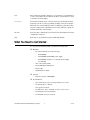
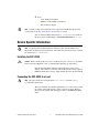
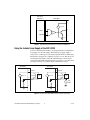
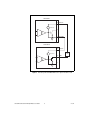
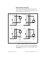
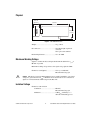
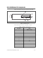
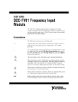
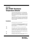
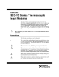
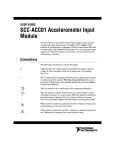
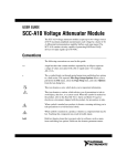
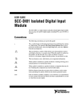
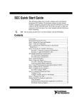
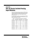
USER GUIDE SCC-CO20 Isolated Current Output Module The SCC-CO20 is an isolated current output module that outputs up to 20 mA. The output current level is proportional to the voltage applied to the module by an analog output channel of an E/M Series DAQ device. Conventions The following conventions are used in this guide: <> Angle brackets that contain numbers separated by an ellipsis represent a range of values associated with a bit or signal name—for example, AO <3..0>. » The » symbol leads you through nested menu items and dialog box options to a final action. The sequence File»Page Setup»Options directs you to pull down the File menu, select the Page Setup item, and select Options from the last dialog box. This icon denotes a note, which alerts you to important information. This icon denotes a caution, which advises you of precautions to take to avoid injury, data loss, or a system crash. When this symbol is marked on the product, refer to the Read Me First: Safety and Radio-Frequency Interference document, shipped with the product, for precautions to take. When symbol is marked on a product, it denotes a warning advising you to take precautions to avoid electrical shock. When symbol is marked on a product, it denotes a component that may be hot. Touching this component may result in bodily injury. bold Bold text denotes items that you must select or click in the software, such as menu items and dialog box options. Bold text also denotes parameter names. italic Italic text denotes variables, emphasis, a cross-reference, or an introduction to a key concept. Italic text also denotes text that is a placeholder for a word or value that you must supply. monospace Text in this font denotes text or characters that you should enter from the keyboard, sections of code, programming examples, and syntax examples. This font is also used for the proper names of disk drives, paths, directories, programs, subprograms, subroutines, device names, functions, operations, variables, filenames, and extensions. SC-2345 SC-2345 refers to both the SC-2345 connector block and the SC-2345 with configurable connectors. SCC SCC refers to any SCC Series signal conditioning module. What You Need to Get Started To set up and use the SCC-CO20, you need the following items: ❑ Hardware – SC-2345/2350 with one of the following: • SCC-PWR01 • SCC-PWR02 and the PS01 power supply • SCC-PWR03 (requires a 7 to 42 VDC power supply, not included) – One or more SCC-CO20 – 68-pin E/M Series DAQ device – 68-pin cable – Quick Reference Label ❑ Software – The latest version of NI-DAQmx ❑ Documentation – SCC-CO20 Isolated Current Output Module User Guide – SC-2345/2350 User Manual – SCC Quick Start Guide – Read Me First: Safety and Radio-Frequency Interference – Documentation for your hardware – Documentation for your software SCC-CO20 Isolated Current Output Module User Guide 2 ni.com ❑ Tools – 1/8 in. flathead screwdriver – Numbers 1 and 2 Phillips screwdrivers – Wire insulation stripper Software scaling of measurements is not supported on the Macintosh operating system. Refer to the SCC-CO20 Module Pin Assignments section. Note You can download NI documents from ni.com/manuals. To download the latest version of NI-DAQmx, click Download Software at ni.com. Device Specific Information For general SCC module installation and signal connection information, and information about the SC-2345/2350 carrier, refer to the SCC Quick Start Guide, available for download at ni.com/manuals. Note Installing the SCC-CO20 Caution Refer to the Read Me First: Safety and Radio-Frequency Interference document before removing equipment covers or connecting/disconnecting any signal wires. Plug the SCC-CO20 into either SC-2345/2350 analog output socket J(X+17), where X is 0 or 1. The SC-2345/2350 routes the voltage output of E/M Series DAQ device analog output channel AO (X) to the SCC-CO20. Connecting the SCC-CO20 to a Load The signal names have changed. Refer to ni.com/info and enter rdtntg to confirm the signal names. Note The screw terminals are labeled by pin number <1..3>. Pin 1 is the ground, pin 2 is the current sink, and pin 3 is the isolated loop supply. Figure 1 shows how the ground, sink, and supply connect to the E/M Series DAQ device. © National Instruments Corporation 3 SCC-CO20 Isolated Current Output Module User Guide E/M Series DAQ Device SCC-CO20 3 + – 15 V iso 2 AO (X ) AO GND 1 I Figure 1. SCC-CO20 Signal Connections to E/M Series DAQ Device Using the Isolated Loop Supply of the SCC-CO20 You can connect the SCC-CO20 to a load using either the isolated internal loop supply or an external supply. The internal loop supply outputs a voltage of 15 V with respect to the isolated ground reference. When using the internal loop supply, the compliance voltage is 12.5 V. This allows for a maximum load resistance of 625 Ω at 20 mA. Figure 2 shows how to connect the SCC-CO20, using the internal loop supply, to a nonreferenced (floating) load and to a load with a high common-mode voltage. SCC-CO20 SCC-CO20 3 SUPPLY + – 15 V iso 0–20 mA 3 SUPPLY + – Load 15 V iso 2 0–20 mA Load 2 SINK SINK 1 + – High CMV 1 I I Figure 2. Connecting the SCC-CO20 Using the Internal Loop Supply SCC-CO20 Isolated Current Output Module User Guide 4 ni.com Note If your load is grounded and you are using the internal supply, connect the load ground to the current sink terminal at pin 2 on the SCC-CO20. Do not connect the load ground to the isolated ground terminal because doing so could defeat the module isolation. Driving Higher-Resistance Loads with the SCC-CO20 In order to calculate the supply voltage your application requires, multiply the load resistance by the current you need to sink, then add 2.5 V for the voltage drop across the protection diode and the current-sink MOSFET. If you need a higher voltage than the 15 V provided by the internal loop supply, you can either add a second SCC-CO20 module or provide an external loop supply. Adding a Second SCC-CO20 Module You can add another SCC-CO20 loop supply to create a supply of 30 V, as shown in Figure 3. Do not use more than two SCC-CO20 modules on a single circuit, because the resulting voltage can cause overheating and damage the modules and other equipment. © National Instruments Corporation 5 SCC-CO20 Isolated Current Output Module User Guide SCC-CO20 3 SUPPLY + – 15 V iso 2 1 ISO GND I SCC-CO20 3 + – SUPPLY 15 V iso Load 2 SINK 1 I Figure 3. Connecting Two SCC-CO20 Modules to a Higher-Resistance Load SCC-CO20 Isolated Current Output Module User Guide 6 ni.com Using an External Loop Supply In order for the current sink to operate properly with an external loop supply, the voltage must be within the range of 3 to 42 V. If the voltage is too high, overheating can occur and damage the module. Figure 4 shows four configurations using an external loop supply. SCC-CO20 2 SCC-CO20 SINK 2 SINK + – Load 0–20 mA 0–20 mA + – Load 1 ISO GND 1 ISO GND I I a. Nonreferenced load and external voltage supply (two circuits) SCC-CO20 2 SCC-CO20 SINK 2 SINK + – Load 0–20 mA 0–20 mA + – Load 1 ISO GND I 1 ISO GND + – High CMV I + – High CMV b. Referenced load and external voltage supply (two circuits) Figure 4. Connecting the SCC-CO20 Using an External Loop Supply When you use an external loop supply, the order of the supply and load does not matter as long as you do not create a second loop through which current flows. If both the supply and the load are grounded, connect the signals as shown in Figure 5. © National Instruments Corporation 7 SCC-CO20 Isolated Current Output Module User Guide SCC-CO20 2 SINK + – 0–20 mA 1 ISO GND Load I Figure 5. Connecting the SCC-CO20 to a Grounded External Loop Supply and a Grounded Load For information about how to configure the SCC-CO20 module using NI-DAQmx, refer to the SCC Quick Start Guide. Calibrating Gain and Offset Errors The SCC-CO20 is calibrated at the factory before shipment. If you want to adjust the gain and offset of the SCC-CO20 in your system using an E/M Series DAQ device, you need a current meter (ammeter) with an accuracy of at least ±2 μA. To adjust the gain and offset of the SCC-CO20, complete the following steps: 1. Disconnect the load from the SCC-CO20 you want to calibrate. 2. Set an output range of 0 to 10 V for AO (X), the E/M Series DAQ device channel connected to the SCC-CO20. 3. Connect the negative lead of the ammeter to the current sink (pin 2) and the positive lead to the current supply (pin 3) of the SCC-CO20. 4. Using your software, have AO (X) output 10 mVDC. 5. Adjust the offset potentiometer on the top of the SCC-CO20 until the ammeter reads 20 μA. The offset is now calibrated. 6. Using your software, have AO (X) output 9 VDC. 7. Adjust the gain potentiometer on the top of the SCC-CO20 until the ammeter reads 18 mA. The gain is now calibrated. SCC-CO20 Isolated Current Output Module User Guide 8 ni.com Note Normally you would adjust to 0 μA in order to calibrate the offset, but because the SCC-CO20 cannot source current, it is impossible to know when you have adjusted past 0 μA. Using the SCC-CO20 The SCC-CO20 is a 0 to 20 mA programmable current sink. The current output is controlled by AO (X), a 0 to 10 V unipolar DAC output channel of an E/M Series DAQ device. The relationship between the AO (X) voltage level and the current output of the SCC-CO20 is linear and is described by the following equation: V AO ( X ) ---------------- = I CO20 500 where VAO (X) is the AO (X) voltage level. ICO20 is the SCC-CO20 current output in amperes. The current sink is an N-channel power MOSFET sink to an isolated ground reference. You can use the SCC-CO20 with industry-standard 0 to 20 or 4 to 20 mA current loops. Note The current sink does not source current. If the input voltage is 0 V or less, the module sinks 0 mA. Isolated Ground Reference Each SCC-CO20 module is referenced to its own isolated ground. Each isolated ground can have up to 60 VDC of common-mode voltage between itself and any other channel ground or chassis ground. Refer to the Connecting the SCC-CO20 to a Load section for different ways to use the isolated ground in signal connections. © National Instruments Corporation 9 SCC-CO20 Isolated Current Output Module User Guide Specifications These ratings are typical at 25 °C unless otherwise stated. Electrical Number of output channels.....................1 Output referencing ..................................Nonreferenced (floating) Input range ..............................................0 to 10 V Output range ...........................................0 to 20 mA Voltage compliance ................................12.5 V Maximum load resistance 5 mA ................................................2,500 Ω 10 mA ..............................................1,250 Ω 15 mA ..............................................830 Ω 20 mA ..............................................625 Ω Absolute accuracy...................................0.1% of full-scale output range Temperature drift ....................................0.5 μA/°C typ 1 μA/°C max Power Requirement Analog power .........................................175 mW max +15 V ...............................................5.8 mA max –15 V ...............................................5.8 mA max Digital power (+5 V) ..............................645 mW +5 V .................................................129 mA max SCC-CO20 Isolated Current Output Module User Guide 10 ni.com Physical 1.87 cm (0.74 in.) 7.93 cm (3.12 in.) 3.55 cm (1.4 in.) Figure 6. SCC-CO20 Dimensions Weight .................................................... 28 g (1.0 oz) I/O connectors ........................................ One 20-pin right-angle male connector One 3-pin screw terminal Field-wiring diameter............................. 28 to 16 AWG Maximum Working Voltage (Signal + common-mode) each input should remain within 42.4 Vpeak or 60 VDC of ground. Maximum working voltage refers to the signal voltage plus the CMV. Channel-to-earth (inputs) ....................... 42.4 Vpeak or 60 VDC, Measurement Category I This device is rated for Measurement Category I and is intended to carry signal voltages no greater than 42.4 Vpeak or 60 VDC. Do not use this device for connection to signals or for measurements within Categories II, III, or IV. Caution Isolation Voltage Channel-to-earth isolation Continuous ...................................... 60 VDC, Measurement Category I Withstand ........................................ 2300 Vrms verified by a 5 s dielectric withstand type test © National Instruments Corporation 11 SCC-CO20 Isolated Current Output Module User Guide Environmental Operating temperature ............................0 to 50 °C Storage temperature ................................–20 to 70 °C Humidity .................................................10 to 90% RH, noncondensing Maximum altitude...................................2,000 m Pollution Degree (indoor use only) ........2 Safety This product meets the requirements of the following standards of safety for electrical equipment for measurement, control, and laboratory use: • IEC 61010-1, EN 61010-1 • UL 61010-1, CSA 61010-1 Note For UL and other safety certifications, refer to the product label or the Online Product Certification section. Electromagnetic Compatibility This product meets the requirements of the following EMC standards for electrical equipment for measurement, control, and laboratory use: • EN 61326 (IEC 61326): Class A emissions; Basic immunity • EN 55011 (CISPR 11): Group 1, Class A emissions • AS/NZS CISPR 11: Group 1, Class A emissions • FCC 47 CFR Part 15B: Class A emissions • ICES-001: Class A emissions For the standards applied to assess the EMC of this product, refer to the Online Product Certification section. Note Note For EMC compliance, operate this product according to the documentation. Note For EMC compliance, operate this device with shielded cables. CE Compliance This product meets the essential requirements of applicable European Directives as follows: • 2006/95/EC; Low-Voltage Directive (safety) • 2004/108/EC; Electromagnetic Compatibility Directive (EMC) SCC-CO20 Isolated Current Output Module User Guide 12 ni.com Online Product Certification Refer to the product Declaration of Conformity (DoC) for additional regulatory compliance information. To obtain product certifications and the DoC for this product, visit ni.com/certification, search by model number or product line, and click the appropriate link in the Certification column. Environmental Management NI is committed to designing and manufacturing products in an environmentally responsible manner. NI recognizes that eliminating certain hazardous substances from our products is beneficial to the environment and to NI customers. For additional environmental information, refer to the NI and the Environment Web page at ni.com/environment. This page contains the environmental regulations and directives with which NI complies, as well as other environmental information not included in this document. Waste Electrical and Electronic Equipment (WEEE) EU Customers At the end of the life cycle, all products must be sent to a WEEE recycling center. For more information about WEEE recycling centers and National Instruments WEEE initiatives, visit ni.com/environment/weee. ⬉ᄤֵᙃѻક∵ᶧࠊㅵ⧚ࡲ⊩ ˄Ё RoHS˅ Ёᅶ᠋ National Instruments ヺড়Ё⬉ᄤֵᙃѻકЁ䰤ࠊՓ⫼ᶤѯ᳝ᆇ⠽䋼ᣛҸ (RoHS)DŽ ݇Ѣ National Instruments Ё RoHS ড়㾘ᗻֵᙃˈ䇋ⱏᔩ ni.com/environment/rohs_chinaDŽ (For information about China RoHS compliance, go to ni.com/environment/rohs_china.) © National Instruments Corporation 13 SCC-CO20 Isolated Current Output Module User Guide SCC-CO20 Module Pin Assignments Figure 7 shows the I/O connector pins on the bottom of the module. 4 1 2 5 1 Pin 1 2 Pin 2 3 PWB Key 4 3 Pin 19 5 Pin 20 Figure 7. SCC-CO20 Bottom View Table 1 lists the signal connection corresponding to each pin. Table 1. SCC-CO20 Pin Signal Connections Pin Number Signal 1 E/M Series AO (X) 2 E/M Series AO GND 3 — 4 E/M Series AO GND 5 — 6 — 7 — 8 — 9 +5 V 10 GND 11 — 12 +5 V REF 13 +15 V SCC-CO20 Isolated Current Output Module User Guide 14 ni.com Table 1. SCC-CO20 Pin Signal Connections (Continued) Pin Number Signal 14 –15 V 15 — 16 — 17 — 18 — 19 — 20 — National Instruments, NI, ni.com, and LabVIEW are trademarks of National Instruments Corporation. Refer to the Terms of Use section on ni.com/legal for more information about National Instruments trademarks. Other product and company names mentioned herein are trademarks or trade names of their respective companies. For patents covering National Instruments products/technology, refer to the appropriate location: Help»Patents in your software, the patents.txt file on your media, or the National Instruments Patent Notice at ni.com/patents. © 2002–2008 National Instruments Corporation. All rights reserved. 371078D-01 Aug08