1
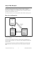
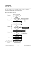
Getting Started with Your STD-GPIB and the
NI-488.2™ Software for Windows
December 1995 Edition
Part Number 321042A-01
© Copyright 1995 National Instruments Corporation.
All Rights Reserved.
National Instruments Corporate Headquarters
6504 Bridge Point Parkway
Austin, TX 78730-5039
(512) 794-0100
Technical support fax: (800) 328-2203
(512) 794-5678
Branch Offices:
Australia 03 9 879 9422, Austria 0662 45 79 90 0, Belgium 02 757 00 20,
Canada (Ontario) 519 622 9310, Canada (Québec) 514 694 8521,
Denmark 45 76 26 00, Finland 90 527 2321, France 1 48 14 24 24,
Germany 089 741 31 30, Hong Kong 2645 3186, Italy 02 48301892,
Japan 03 5472 2970, Korea 02 596 7456, Mexico 5 202 2544,
Netherlands 03480 33466, Norway 32 84 84 00, Singapore 2265886,
Spain 91 640 0085, Sweden 08 730 49 70, Switzerland 056 20 51 51,
Taiwan 02 377 1200, U.K. 01635 523545
Limited Warranty
The STD-GPIB hardware is warranted against defects in materials and workmanship for
a period of two years from the date of shipment, as evidenced by receipts or other
documentation. National Instruments will, at its option, repair or replace equipment that
proves to be defective during the warranty period. This warranty includes parts and
labor.
The media on which you receive National Instruments software are warranted not to fail
to execute programming instructions, due to defects in materials and workmanship, for a
period of 90 days from date of shipment, as evidenced by receipts or other
documentation. National Instruments will, at its option, repair or replace software media
that do not execute programming instructions if National Instruments receives notice of
such defects during the warranty period. National Instruments does not warrant that the
operation of the software shall be uninterrupted or error free.
A Return Material Authorization (RMA) number must be obtained from the factory and
clearly marked on the outside of the package before any equipment will be accepted for
warranty work. National Instruments will pay the shipping costs of returning to the
owner parts which are covered by warranty.
National Instruments believes that the information in this manual is accurate. The
document has been carefully reviewed for technical accuracy. In the event that technical
or typographical errors exist, National Instruments reserves the right to make changes to
subsequent editions of this document without prior notice to holders of this edition. The
reader should consult National Instruments if errors are suspected. In no event shall
National Instruments be liable for any damages arising out of or related to this document
or the information contained in it.
EXCEPT AS SPECIFIED HEREIN, NATIONAL INSTRUMENTS MAKES NO
WARRANTIES , EXPRESS OR IMPLIED , AND SPECIFICALLY DISCLAIMS ANY
WARRANTY OF MERCHANTABILITY OR FITNESS FOR A PARTICULAR PURPOSE .
C USTOMER 'S RIGHT TO RECOVER DAMAGES CAUSED BY FAULT OR NEGLIGENCE
ON THE PART OF NATIONAL INSTRUMENTS SHALL BE LIMITED TO THE AMOUNT
THERETOFORE PAID BY THE CUSTOMER . N ATIONAL INSTRUMENTS WILL NOT BE
LIABLE FOR DAMAGES RESULTING FROM LOSS OF DATA , PROFITS, USE OF
PRODUCTS, OR INCIDENTAL OR CONSEQUENTIAL DAMAGES , EVEN IF ADVISED OF
THE POSSIBILITY THEREOF. This limitation of the liability of National Instruments will
apply regardless of the form of action, whether in contract or tort, including negligence.
Any action against National Instruments must be brought within one year after the cause
of action accrues. National Instruments shall not be liable for any delay in performance
due to causes beyond its reasonable control. The warranty provided herein does not
cover damages, defects, malfunctions, or service failures caused by owner's failure to
follow the National Instruments installation, operation, or maintenance instructions;
owner's modification of the product; owner's abuse, misuse, or negligent acts; and power
failure or surges, fire, flood, accident, actions of third parties, or other events outside
reasonable control.
Copyright
Under the copyright laws, this publication may not be reproduced or transmitted in any
form, electronic or mechanical, including photocopying, recording, storing in an
information retrieval system, or translating, in whole or in part, without the prior written
consent of National Instruments Corporation.
Trademarks
LabVIEW ®, NAT4882 ®, NI-488 ®, Turbo488 ®, NI-488.2™ , and TNT4882C™ are
trademarks of National Instruments Corporation.
Product and company names listed are trademarks or trade names of their respective
companies.
WARNING REGARDING MEDICAL AND CLINICAL
USE OF NATIONAL INSTRUMENTS PRODUCTS
National Instruments products are not designed with components and testing intended to
ensure a level of reliability suitable for use in treatment and diagnosis of humans.
Applications of National Instruments products involving medical or clinical treatment can
create a potential for accidental injury caused by product failure, or by errors on the part
of the user or application designer. Any use or application of National Instruments
products for or involving medical or clinical treatment must be performed by properly
trained and qualified medical personnel, and all traditional medical safeguards,
equipment, and procedures that are appropriate in the particular situation to prevent
serious injury or death should always continue to be used when National Instruments
products are being used. National Instruments products are NOT intended to be a
substitute for any form of established process, procedure, or equipment used to monitor
or safeguard human health and safety in medical or clinical treatment.
FCC/DOC Radio Frequency Interference Compliance
This equipment generates and uses radio frequency energy and, if not installed and used
in strict accordance with the instructions in this manual, may cause interference to radio
and television reception. This equipment has been tested and found to comply with the
following two regulatory agencies:
Federal Communications Commission
This device complies with Part 15 of the Federal Communications Commission (FCC)
Rules for a Class A digital device. Operation is subject to the following two conditions:
1.
This device may not cause harmful interference in commercial environments.
2.
This device must accept any interference received, including interference that may
cause undesired operation.
Canadian Department of Communications
This device complies with the limits for radio noise emissions from digital apparatus set
out in the Radio Interference Regulations of the Canadian Department of
Communications (DOC).
Le présent appareil numérique n’émet pas de bruits radioélectriques dépassant les limites
applicables aux appareils numériques de classe A prescrites dans le règlement sur le
brouillage radioélectrique édicté par le ministère des communications du Canada.
Instructions to Users
These regulations are designed to provide reasonable protection against harmful
interference from the equipment to radio reception in commercial areas. Operation of
this equipment in a residential area is likely to cause harmful interference, in which case
the user will be required to correct the interference at his own expense.
There is no guarantee that interference will not occur in a particular installation.
However, the chances of interference are much less if the equipment is installed and used
according to this instruction manual.
If the equipment does cause interference to radio or television reception, which can be
determined by turning the equipment on and off, one or more of the following
suggestions may reduce or eliminate the problem.
•
Operate the equipment and the receiver on different branches of your AC electrical
system.
•
Move the equipment away from the receiver with which it is interfering.
•
Reorient or relocate the receiver’s antenna.
•
Be sure that the equipment is plugged into a grounded outlet and that the grounding
has not been defeated with a cheater plug.
Notice to user: Changes or modifications not expressly approved by National
Instruments could void the user’s authority to operate the equipment
under the FCC Rules.
If necessary, consult National Instruments or an experienced radio/television technician
for additional suggestions. The following booklet prepared by the FCC may also be
helpful: How to Identify and Resolve Radio-TV Interference Problems. This booklet is
available from the U.S. Government Printing Office, Washington, DC 20402, Stock
Number 004-000-00345-4.
Contents
About This Manual ............................................................................................... ix
How to Use the Manual Set ............................................................................. ix
Organization of This Manual........................................................................... x
Conventions Used in This Manual................................................................... x
Related Documentation ................................................................................... xi
Customer Communication ............................................................................... xii
Chapter 1
Introduction .............................................................................................................. 1-1
How to Use This Manual................................................................................. 1-1
What You Need to Get Started ........................................................................ 1-2
Hardware Description ...................................................................................... 1-2
Software Description ....................................................................................... 1-3
ni-pnp Utility Overview .................................................................... 1-3
Optional Programming Environments............................................................. 1-3
Chapter 2
Hardware Configuration and Installation ................................................... 2-1
Install the Hardware......................................................................................... 2-2
Configure the Hardware................................................................................... 2-4
Selecting the Base I/O Address ......................................................... 2-6
Selecting the Interrupt Request Line ................................................. 2-9
Selecting the DMA Channel ............................................................. 2-12
Using Programmed I/O for GPIB Transfers ..................................... 2-14
Setting the Shield Ground Configuration .......................................... 2-14
Setting the Operating Mode............................................................... 2-15
Chapter 3
Software Installation and Configuration ..................................................... 3-1
NI-488.2 Software Components ...................................................................... 3-1
Install the Software .......................................................................................... 3-1
Configure the Software .................................................................................... 3-2
Chapter 4
Installation Verification and Troubleshooting ........................................... 4-1
Troubleshooting ni-pnp Error Messages ......................................................... 4-1
Run the Hardware Diagnostic Test .................................................................. 4-2
Troubleshooting Hardware Diagnostic Test Error Messages ........... 4-2
Using Single-Cycle DMA................................................... 4-2
Correcting Hardware Settings............................................. 4-3
Run the Software Diagnostic Test ................................................................... 4-4
Troubleshooting Software Diagnostic Test Error Messages............. 4-4
Presence Test of Software Components ............................. 4-5
Presence Test of Driver....................................................... 4-5
© National Instruments Corp.
vii
STD-GPIB for Windows
Contents
Presence Test of Module..................................................... 4-5
GPIB Cables Connected ..................................................... 4-6
Common Questions ......................................................................................... 4-6
Chapter 5
Using Your NI-488.2 Software .......................................................................... 5-1
Introduction to the Win16 Interactive Control Utility..................................... 5-1
General Programming Considerations............................................................. 5-1
Appendix A
Hardware Specifications .................................................................................... A-1
Appendix B
Interrupt Routing ................................................................................................... B-1
Frontplane Interrupts ....................................................................................... B-1
Backplane Interrupts ........................................................................................ B-2
Setting Interrupts on the STD-GPIB................................................................ B-2
Appendix C
Customer Communication ................................................................................. C-1
Glossary ...................................................................................................................... G-1
Figures
Figure
Figure
Figure
Figure
Figure
Figure
Figure
Figure
Figure
Figure
Figure
2-1.
2-2.
2-3.
2-4.
2-5.
2-6.
2-7.
2-8.
2-9.
2-10.
2-11.
Installing the STD-GPIB Board ............................................................ 2-2
Completed Installation for the STD-GPIB ........................................... 2-3
STD-GPIB Parts Locator Diagram ....................................................... 2-5
Base I/O Address Switch Settings ........................................................ 2-8
Interrupt Jumper Setting for IRQ11 in a Ziatech Computer ................. 2-10
Interrupt Jumper Setting for IRQ5 in a WinSystems Computer........... 2-11
Jumper Setting for Disabling Interrupts................................................ 2-12
DMA Channel Jumper Setting for DMA Channel 6............................. 2-13
DMA Jumper Setting for No DMA Channel ........................................ 2-14
Ground Configuration Jumper Settings................................................. 2-15
Jumper Settings for 8-Bit and 16-Bit Mode Operation......................... 2-15
Tables
Table 2-1.
Table 2-2.
Table 2-3.
Hardware Default Settings .................................................................... 2-1
Possible Base I/O Address Switch Settings .......................................... 2-6
DMA Channels ..................................................................................... 2-12
Table A-1.
Table A-2.
Table A-3.
Electrical Characteristics....................................................................... A-1
Environmental Characteristics .............................................................. A-1
Physical Characteristics ........................................................................ A-1
Table B-1.
Table B-2.
J3 Frontplane Interrupt Connector Pinouts ........................................... B-1
STD-GPIB Interrupt Routing................................................................ B-2
STD-GPIB for Windows
viii
© National Instruments Corp.
About This Manual
This manual contains instructions to help you install and configure the National
Instruments STD-GPIB interface board and the NI-488.2 software for Windows. The
interface board is intended for use in a STD/STD32 system. The NI-488.2 software is
intended for use with Windows version 3.1.
This manual assumes that you are already familiar with the Windows operating system.
How to Use the Manual Set
Getting Started
Manual
Installation and
Configuration
Experienced
Users
Novice
Users
NI-488.2 User
Manual for Windows
NI-488.2 Function
Reference Manual for
DOS/Windows
Application
Development
and Examples
Function
and Routine
Descriptions
Use this getting started manual to install and configure your STD-GPIB and the NI-488.2
software for Windows.
Use the NI-488.2 User Manual for Windows to learn the basics of GPIB and how to
develop an application program. The manual also contains debugging information and
detailed examples.
Use the NI-488.2 Function Reference Manual for DOS/Windows for specific NI-488
function and NI-488.2 routine information, such as format, parameters, and possible
errors.
© National Instruments Corp.
ix
STD-GPIB for Windows
About This Manual
Organization of This Manual
This manual is organized as follows:
•
Chapter 1, Introduction, explains how to use this manual, lists what you need to get
started, and briefly describes the STD-GPIB and the NI-488.2 software.
•
Chapter 2, Hardware Configuration and Installation , contains instructions to help
you configure and install your STD-GPIB.
•
Chapter 3, Software Installation and Configuration , contains instructions to help you
install and configure your NI-488.2 software.
•
Chapter 4, Installation Verification and Troubleshooting, describes how to verify the
hardware and software installation and how to troubleshoot problems.
•
Chapter 5, Using Your NI-488.2 Software, introduces the Win16 Interactive Control
utility and lists some programming considerations.
•
Appendix A, Hardware Specifications, describes the characteristics of the
STD -GPIB and the recommended operating conditions.
•
Appendix B, Interrupt Routing, contains useful information for you if you want to
configure the interrupt lines for an STD/STD32 computer not manufactured by
WinSystems or Ziatech, or a computer that is not AT-compatible.
•
Appendix C, Customer Communication, contains forms you can use to request help
from National Instruments or to comment on our products and manuals.
•
The Glossary contains an alphabetical list and a description of terms used in this
manual, including abbreviations, acronyms, metric prefixes, mnemonics, and
symbols.
Conventions Used in This Manual
The following conventions are used in this manual.
bold
Bold text denotes menus, menu items, dialog buttons, or
options.
italic
Italic text denotes emphasis, a cross reference, or an
introduction to a key concept.
bold italic
Bold italic text denotes a note, caution, or warning.
STD-GPIB for Windows
x
© National Instruments Corp.
About This Manual
monospace
Text in this font denotes text or characters that are to be
literally input from the keyboard, sections of code,
programming examples, and syntax examples. This font is
also used for the proper names of disk drives, directories,
programs, subprograms, subroutines, device names, functions,
variables, field names and filenames.
italic monospace
Italic text in this font denotes that you must supply the
appropriate words or values in place of these items.
bold monospace
Bold text in this font denotes the messages and responses that
the computer automatically prints to the screen.
<>
Angle brackets enclose the name of a key on the keyboard—
for example, <PageDown>.
-
A hyphen between two or more key names enclosed in angle
brackets denotes that you should simultaneously press the
named keys—for example, <Control-Alt-Delete>.
IEEE 488 and
IEEE 488.2
IEEE 488 and IEEE 488.2 refer to the ANSI/IEEE Standard
488.1-1987 and the ANSI/IEEE Standard 488.2-1987,
respectively, which define the GPIB.
Abbreviations, acronyms, metric prefixes, mnemonics, symbols, and terms are listed in
the Glossary.
Related Documentation
The following documents contain information that you may find helpful as you read this
manual.
•
ANSI/IEEE Standard 488.1-1987, IEEE Standard Digital Interface for
Programmable Instrumentation
•
ANSI/IEEE Standard 488.2-1987, IEEE Standard Codes, Formats,
Protocols, and Common Commands
•
Microsoft Windows User's Guide, Microsoft Corporation
•
STD Specification, Version 2.1
© National Instruments Corp.
xi
STD-GPIB for Windows
About This Manual
Customer Communication
National Instruments wants to receive your comments on our products and manuals. We
are interested in the applications you develop with our products, and we want to help if
you have problems with them. To make it easy for you to contact us, this manual
contains comment and configuration forms for you to complete. These forms are in
Appendix C, Customer Communication, at the end of this manual.
STD-GPIB for Windows
xii
© National Instruments Corp.
Chapter 1
Introduction
This chapter explains how to use this manual, lists what you need to get started, and
briefly describes the STD-GPIB and the NI-488.2 software.
How to Use This Manual
Chapter 1
Gather What You Need
to Get Started
Need to
Change Hardware
Settings?
Yes
Configure the Hardware
Chapter 2
No
Install the Hardware
Install the Software
Chapter 3
Need to
Change Software
Settings?
Yes
Configure the Software
No
Verify the Installation
Chapter 4
Passes?
No
Troubleshooting
Yes
Run Win16 Interactive
Control Utility
Chapter 5
Review Programming
Considerations
User Manual and
Function Reference
Manual
Write Application Program
© National Instruments Corp.
1-1
STD-GPIB for Windows
Introduction
Chapter 1
What You Need to Get Started
STD-GPIB
STD-GPIB feedthrough front panel assembly
3.5 in. high density (1.44 MB) distribution disk:
NI-488.2 Software for Windows and the AT-GPIB/TNT+, AT-GPIB/TNT (PnP),
EISA-GPIB and AT-GPIB/TNT
Microsoft Windows version 3.1 installed on your system
Hardware Description
The STD specification, IEEE 961, is an 8-bit microprocessor bus standard that combines
small card size, flexibility, and expandability for industrial and commercial applications
that require dependable and expandable resources. Beyond the IEEE 961 specification,
the STD bus Manufacturers' Group (STDMG) maintains the STD-80 Series specification,
which includes recent STD bus enhancements. The changes and additions enable the
STD bus to support 16-bit data transfers for memory and I/O cards, by multiplexing the
high data byte with eight address lines. STD 32, an extension of the original STD bus,
employs EISA technology to provide 16- and 32-bit data transfers across the backplane
without the multiplexing of signals.
The STD-GPIB, equipped with a TNT4882C ASIC, transforms any STD/STD32 system
into a full-functioning GPIB Talker/Listener/Controller. The TNT4882C chip combines
the circuitry of the NAT4882 ASIC, the Turbo488 performance-enhancing ASIC, and
GPIB transceivers to create a single-chip IEEE 488.2 Talker/Listener/Controller
interface. The TNT4882C also implements the HS488 high-speed protocol, which
increases the maximum data transfer rate of the STD-GPIB to over 1 Mbyte/s. For more
information about HS488, refer to Chapter 7, GPIB Programming Techniques, in the
NI -488.2 User Manual for Windows.
The STD-GPIB is functionally identical to the AT-GPIB/TNT and can run any NI-488.2
driver software for the AT-GPIB/TNT. The STD-GPIB can be plugged into a Ziatech
(STD-32) or WinSystems (STD-80) backplane. The STD-GPIB automatically detects the
type of system it is plugged into and configures itself for either multiplexed
(WinSystems) or non-multiplexed (Ziatech) 16-bit data transfers. The STD-GPIB is
equipped with a feedthrough front panel assembly for easy user access to the GPIB port.
You can use standard GPIB cables to connect the STD-GPIB with up to 14 instruments.
If you want to use more than the maximum number of instruments, you can order a bus
extender or expander from National Instruments. Refer to Appendix A, Hardware
Specifications, for more information about the GPIB hardware specifications and
recommended operating conditions.
STD-GPIB for Windows
1-2
© National Instruments Corp.
Chapter 1
Introduction
Software Description
The STD-GPIB uses the NI-488.2 driver software for the AT-GPIB/TNT. The NI-488.2
software for Windows includes a Windows dynamic link library, language interface
libraries, and debugging and development utilities. The NI-488.2 software and GPIB
hardware transform a STD/STD32 system into a GPIB Talker/Listener/Controller that
has complete communications and bus management capability.
ni-pnp Utility Overview
The ni-pnp utility is a small program that runs each time you reboot your system. It
collects information about National Instruments interfaces in your system. In systems
that are Plug and Play ready, ni-pnp simply retrieves the current configuration of each
interface. In systems without Plug and Play system software, ni-pnp performs the
actual configuration of each interface. ni-pnp does not select the resources to assign to
interfaces. If your system does not assign resources, you must run the GPIB software
configuration utility to assign resources to the GPIB interfaces. After the configuration
of each interface is determined, ni-pnp provides this information to the NI-488.2
driver.
Optional Programming Environments
Your kit includes the NI-488.2 software for Windows. In addition, you can order the
LabWindows ®/CVI or LabVIEW software from National Instruments.
LabWindows/CVI and LabVIEW include instrument driver libraries that make it easier to
communicate with your GPIB instruments.
LabWindows/CVI is an interactive ANSI C development environment for building test
and measurement and instrument control systems. It includes interactive code-generation
tools and a graphical editor for building custom user interfaces. It also includes built-in
libraries for IEEE 488.2, VXI, RS-232 control, and plug-in data acquisition. When you
order LabWindows/CVI, you also get more than 300 complete instrument drivers, which
are modular, source-code programs that handle the communication with your instrument
so that you do not have to learn the programming details.
LabVIEW is a complete programming environment that departs from the sequential
nature of traditional programming languages and features a graphical programming
environment. It includes all the tools needed for instrument control, data acquisition,
analysis, and presentation. LabVIEW also includes an extensive instrument driver
library.
For more information about LabWindows/CVI and LabVIEW, contact National
Instruments.
© National Instruments Corp.
1-3
STD-GPIB for Windows
Chapter 2
Hardware Configuration and Installation
This chapter contains instructions to help you configure and install your STD-GPIB.
Warning:
Electrostatic discharge can damage some components on your
STD-GPIB. To avoid such damage in handling the module, touch the
antistatic plastic package to a metal part of your computer chassis before
removing the module from the package.
The STD-GPIB default settings are suitable for most STD/STD32 systems. However, if
any of the following situations is true, you must reconfigure the hardware.
•
If the default settings conflict with another device in your system
•
If you need to install more than one STD-GPIB
•
If your system CPU board supports only 8-bit STD bus transfers
If you already have STD-GPIB modules installed in your system, you can run the GPIB
Information utility to determine how the modules are configured. For more information
about the GPIB Information utility, refer to Chapter 4, Debugging Your Application, in
the NI-488.2 User Manual for Windows.
Table 2-1 shows the default settings for the switches and jumpers on the STD-GPIB.
Table 2-1. Hardware Default Settings
Characteristic
Base I/O Address (hex)
DMA Channel
*
Default
Setting
2C0
5
Interrupt Line (IRQ)
None*
Operation Mode
16-Bit
The jumper settings for any interrupt level depend on which computer you are using
(Ziatech or WinSystems), so the STD-GPIB is shipped with interrupts disabled.
However, the NI-488.2 software is configured to use IRQ11 by default and will not
function properly until you disable interrupts in the GPIB software configuration
utility. Your hardware and software settings must match.
To modify the default settings of the STD-GPIB, refer to the Configure the Hardware
section of this chapter. If you do not need to reconfigure the STD-GPIB, refer to the
Install the Hardware section.
© National Instruments Corp.
2-1
STD-GPIB for Windows
Hardware Configuration and Installation
Chapter 2
Install the Hardware
Perform the following steps to install the STD-GPIB.
1.
Power off your STD/STD32 system. Keep the system plugged in so that it remains
grounded while you install the STD-GPIB.
2.
Remove any front plates that are blocking the access to the backplane slot.
3.
Insert the STD-GPIB into any unused slot with the GPIB connector facing away
from the backplane, as shown in Figure 2-1.
5
6
7
OFF
ON
3
1
2
3
GPIB Ribb on Cable
GPIB Connector
STD-GPIB Board
4
5
6
1
2
4
Plug-In Board
STD/STD32 System
Backplane Slot
7
Feedthrough Panel Assembly
Figure 2-1. Installing the STD-GPIB Board
4.
Plug the GPIB ribbon cable into the GPIB connector on the STD-GPIB. The header
is keyed so that it fits in only one direction. Do not force the GPIB ribbon cable
connector into place. The GPIB ribbon cable is 5 in. long and terminated with a
panel-mount GPIB connector that is mounted to a special GPIB front plate for easy
access in your system.
STD-GPIB for Windows
2-2
© National Instruments Corp.
Chapter 2
Note:
Hardware Configuration and Installation
If you plan to perform HS488 high-speed protocol transfers, you must
configure the NI-488.2 software for the amount of GPIB cable length in
your system. The 5 in. GPIB ribbon cable must be added to your total
GPIB cable length.
5.
Mount the feedthrough panel assembly onto the STD/STD32 card cage using the two
large thumbscrews.
6.
Check that the installation resembles Figure 2-2.
OFF
ON
2
1
Feedthrough Panel Assembly
2
1
Thumbscrews
Figure 2-2. Completed Installation for the STD-GPIB
7.
Power on your system.
After you have installed your STD-GPIB, you are ready to install the NI-488.2 software.
Refer to Chapter 3, Software Installation and Configuration .
© National Instruments Corp.
2-3
STD-GPIB for Windows
Hardware Configuration and Installation
Chapter 2
Configure the Hardware
Follow the instructions in this section to change the hardware settings of the STD-GPIB
before you install it. The default settings are suitable for most STD systems, but you
need to change the hardware settings in the following situations:
•
If you want to use interrupts for the STD-GPIB
•
If the default settings conflict with another device in your system
•
If you are installing more than one STD-GPIB
The default settings for the switches and jumpers on the STD-GPIB are as follows:
•
Base I/O Address (hex): 2C0
•
DMA Channel: 5
•
Interrupt Line (IRQ): None
STD-GPIB for Windows
2-4
© National Instruments Corp.
Chapter 2
Hardware Configuration and Installation
Figure 2-3 shows the location of the configuration jumpers and switches on the
STD-GPIB.
1
2
8
1
2
Interrupt Level
DMA Channel
3
4
3
4
5
7
Assembly Number 5
Serial Number
6
Product Name
Shield Ground
6
7
8
Mode of Operation
Base I/O Address
Figure 2-3. STD-GPIB Parts Locator Diagram
© National Instruments Corp.
2-5
STD-GPIB for Windows
Hardware Configuration and Installation
Chapter 2
Selecting the Base I/O Address
STD/STD32 computers have a segment of address space reserved for input and output.
This segment is referred to as the I/O address space. The base I/O address of an
STD/STD32 module such as the STD-GPIB is the first position in the I/O address space
occupied by the STD/STD32 module.
By default, the STD-GPIB is configured to use base I/O address 2C0 hex. With this
setting, the module uses the I/O address space 2C0 hex through 2DF hex. If this address
range is already in use by another device or if you are installing more than one
STD-GPIB, follow these steps to reconfigure the base I/O address setting.
1.
Choose a new base I/O address setting.
You can configure the base I/O addresses to any setting between 0x100 and 0x3E0
that is a multiple of 0x20 hex. If you are installing more than one STD-GPIB, each
module must use a unique base I/O address.
Table 2-2 lists the possible switch settings, the corresponding base I/O addresses,
and the I/O address space used for each setting. The default settings are in bold
italics.
Table 2-2. Possible Base I/O Address Switch Settings
A9
Switch Setting
A8 A7 A6
A5
Base I/O
Address (hex)
I/O Address Space
Used (hex)
0
1
0
0
0
100
100 to 11F
0
1
0
0
1
120
120 to 13F
0
1
0
1
0
140
140 to 15F
0
1
0
1
1
160
160 to 17F
0
1
1
0
0
180
180 to 19F
0
1
1
0
1
1A0
1A0 to 1BF
0
1
1
1
0
1C0
1C0 to 1DF
0
1
1
1
1
1E0
1E0 to 1FF
1
0
0
0
0
200
200 to 21F
1
0
0
0
1
220
220 to 23F
1
0
0
1
0
240
240 to 25F
1
0
0
1
1
260
260 to 27F
1
0
1
0
0
280
280 to 29F
(continues)
STD-GPIB for Windows
2-6
© National Instruments Corp.
Chapter 2
Hardware Configuration and Installation
Table 2-2. Possible Base I/O Address Switch Settings (Continued)
A9
Switch Setting
A8 A7 A6
A5
Base I/O
Address (hex)
I/O Address Space
Used (hex)
1
0
1
0
1
2A0
2A0 to 2BF
1
0
1
1
0
2C0
2C0 to 2DF
1
0
1
1
1
2E0
2E0 to 2FF
1
1
0
0
0
300
300 to 31F
1
1
0
0
1
320
320 to 33F
1
1
0
1
0
340
340 to 35F
1
1
0
1
1
360
360 to 37F
1
1
1
0
0
380
380 to 39F
1
1
1
0
1
3A0
3A0 to 3BF
1
1
1
1
0
3C0
3C0 to 3DF
1
1
1
1
1
3E0
3E0 to 3FF
2.
Locate the base I/O address switch at SW1 on your STD-GPIB. Refer to the parts
locator diagram, Figure 2-3.
3.
Change the switch settings to configure the STD-GPIB to the new base I/O address.
Press down on the side marked 1 to select a binary value of 1 for the corresponding
address bit. Press down on the 0 side of the switch to select a binary value of 0.
Refer to Figure 2-4 for an example of the switch settings and corresponding base I/O
addresses.
© National Instruments Corp.
2-7
STD-GPIB for Windows
Hardware Configuration and Installation
Chapter 2
Push this side down (ON) for logic 0
Push this side down (OFF) for logic 1
1
0
OFF
1 2 3 4 5
Binary
9
8
7
6
5
Switch Set to Base I/O
Address hex 300
0
Hex
1
1
3
0
0
0
0
0
0
0
0
0
0
1
OFF
1 2 3 4 5
Binary
9
8
7
6
5
Switch Set to Default Base I/O
Address hex 2C0
Hex
1
0
2
1
1
0
0
C
0
0
0
0
0
Figure 2-4. Base I/O Address Switch Settings
4.
Record your new setting on the STD-GPIB Hardware and Software Configuration
Form in Appendix C, Customer Communication.
5.
Remember that after you install the NI-488.2 software, you must use the GPIB
software configuration utility to configure your software settings to match your new
hardware settings. Refer to the Configure the Software section in Chapter 3,
Software Installation and Configuration, for more information.
STD-GPIB for Windows
2-8
© National Instruments Corp.
Chapter 2
Hardware Configuration and Installation
Selecting the Interrupt Request Line
STD/STD32 computers have a series of interrupt lines available to devices. Some of the
interrupt lines reside in the backplane, and the others are available through a 10-pin
frontplane connector. Devices use interrupts to get immediate service from the CPU for
asynchronous events. Your GPIB hardware and the NI-488.2 software use interrupts to
get service from the CPU when necessary.
The STD-GPIB is shipped with interrupts disabled. If you want to select an interrupt
setting for the STD-GPIB, follow these steps to reconfigure the interrupt request line:
1.
Choose a new interrupt request line (IRQ) setting.
If you are installing the STD-GPIB into a Ziatech STD32 AT-compatible computer,
you can configure it to use any of the following interrupt lines: IRQ5, 6, 9, 10, 11,
12, 14, or None. If you are installing the STD-GPIB into a WinSystems
AT-compatible computer, you can configure it to use any of the following interrupt
lines: IRQ5, 7, 9, 10, 11, 12, 14, 15, or None. You may not want to select interrupt
lines 6 or 14, because interrupt line 6 is typically used by the diskette drive controller
and interrupt line 14 is used by the hard disk drive controller on most systems.
If you are installing more than one STD-GPIB, each module must either use a unique
IRQ level or not use interrupts at all.
2.
Find the jumpers at W1 and W2 that set the interrupt request line. Refer to the parts
locator diagram, Figure 2-3.
3.
Change the jumper settings to configure the STD-GPIB to the new interrupt request
line.
To select interrupt lines for a Ziatech STD32 computer, refer to the labels on the left
side of the jumpers, as shown in Figure 2-5. To select interrupt lines for a
WinSystems computer, refer to the labels on the right side of the jumpers, as shown
in Figure 2-6. To disable interrupts, use the jumper setting shown in Figure 2-7.
If you are using the STD-GPIB in a computer that is not manufactured by Ziatech or
WinSystems, or if the computer is not an AT-compatible, find out which interrupt
source corresponds to the interrupt request line you want to use for that computer,
and then consult Appendix B, Interrupt Routing, for the proper jumper settings.
© National Instruments Corp.
2-9
STD-GPIB for Windows
Hardware Configuration and Installation
Chapter 2
Ziatech
W2
Figure 2-5 shows the setting for IRQ11 in a Ziatech AT-compatible computer.
WinSystems
IRQ 5
IRQ 5
IRQ 6
IRQ 9
IRQ 9
IRQ 7
IRQ 14
IRQ 10
IRQ 10
IRQ 11
IRQ 11
IRQ 12
IRQ 14
IRQ 12
W1
IRQ 15
Figure 2-5. Interrupt Jumper Setting for IRQ11 in a Ziatech Computer
STD-GPIB for Windows
2-10
© National Instruments Corp.
Chapter 2
Hardware Configuration and Installation
Ziatech
W2
Figure 2-6 shows the setting for IRQ5 in a WinSystems AT-compatible computer.
WinSystems
IRQ 5
IRQ 5
IRQ 6
IRQ 9
IRQ 9
IRQ 7
IRQ 14
IRQ 10
IRQ 10
IRQ 11
IRQ 11
IRQ 12
IRQ 14
IRQ 12
W1
IRQ 15
Figure 2-6. Interrupt Jumper Setting for IRQ5 in a WinSystems Computer
If you do not want to use interrupts, you can disable interrupt levels on the
STD-GPIB by leaving the jumper as shown in Figure 2-7.
© National Instruments Corp.
2-11
STD-GPIB for Windows
Ziatech
Chapter 2
W2
Hardware Configuration and Installation
WinSystems
IRQ 5
IRQ 5
IRQ 6
IRQ 9
IRQ 9
IRQ 7
IRQ 14
IRQ 10
IRQ 10
IRQ 11
IRQ 11
IRQ 12
IRQ 14
IRQ 12
W1
IRQ 15
Figure 2-7. Jumper Setting for Disabling Interrupts
4.
Record your new setting on the STD-GPIB Hardware and Software Configuration
Form in Appendix C, Customer Communication.
5.
Remember that after you install the NI-488.2 software, you must use the GPIB
software configuration utility to configure your software settings to match your new
hardware settings. Refer to the Configure the Software section in Chapter 3,
Software Installation and Configuration, for more information.
Selecting the DMA Channel
Direct memory access (DMA) refers to data transfers directly to or directly from devices
such as the STD-GPIB and system memory. Your GPIB hardware and the NI-488.2
software are designed to perform DMA. In most cases, data transfers using DMA are
significantly faster than programmed I/O transfers, which use more CPU time.
The STD-GPIB is able to perform DMA transfer through the use of a frontplane DMA
connector. By default, the STD-GPIB is configured to use DMA channel 5. If this is not
an acceptable setting, or if you are installing more than one STD-GPIB, follow these
steps to reconfigure the DMA channel.
Note: The STD-GPIB supports only 16-bit DMA transfers. If your CPU board does
not support 16-bit DMA transfers, you must disable DMA. Refer to Figure 2-9,
which shows how to set the DMA jumpers for no DMA.
STD-GPIB for Windows
2-12
© National Instruments Corp.
Chapter 2
1.
Hardware Configuration and Installation
Choose a new DMA channel setting.
You can use channel 5 or 6. If you are installing more than one STD-GPIB, each
module must either use a unique DMA channel or must not use DMA at all.
2.
Locate the jumpers at W3 that select the DMA channel. Refer to the parts locator
diagram, Figure 2-3.
3.
Change the jumper settings to configure the STD-GPIB to the new DMA channel.
To select a new DMA channel, you must set both the DMA Acknowledge and DMA
Request lines, as shown in Table 2-3.
Table 2-3. DMA Channels
Signal Lines
DMA
Channel
DMA
Acknowledge
DMA
Request
5
DACK5
DRQ5
6
DACK6
DRQ6
W3
Figure 2-8 shows the jumper position for selecting DMA channel 6.
DRQ 6
DACK 6
DRQ 5
DACK 5
Figure 2-8. DMA Channel Jumper Setting for DMA Channel 6
4.
Record your new setting on the STD-GPIB Hardware and Software Configuration
Form in Appendix C, Customer Communication.
5.
Remember that after you install the NI-488.2 software, you must use the GPIB
software configuration utility to configure your software setting to match your new
hardware settings. Refer to the Configure the Software section in Chapter 3,
Software Installation and Configuration, for more information.
© National Instruments Corp.
2-13
STD-GPIB for Windows
Hardware Configuration and Installation
Chapter 2
Using Programmed I/O for GPIB Transfers
W3
As an alternative to DMA transfers, you can use programmed I/O. To use programmed
I/O, you should disable DMA for the STD-GPIB by moving the jumpers as shown in
Figure 2-9.
DRQ 6
DACK 6
DRQ 5
DACK 5
Figure 2-9. DMA Jumper Setting for No DMA Channel
Setting the Shield Ground Configuration
The STD-GPIB is set at the factory with the jumper in place to connect the logic ground
of the STD-GPIB to its shield ground. This configuration minimizes EMI emissions.
If your application requires that logic ground be disconnected from shield ground, follow
these steps:
1.
Refer to Figure 2-3 to locate the shield ground jumper W4 on the STD-GPIB.
2.
Remove the jumper and place it across only one of the jumper pins, as shown in
Figure 2-10.
STD-GPIB for Windows
2-14
© National Instruments Corp.
Chapter 2
Hardware Configuration and Installation
W4
Logic Ground Connected to Shield Ground (Default)
W4
Logic Ground Disconnected from Shield Ground
Figure 2-10. Ground Configuration Jumper Settings
3.
Record the jumper setting on the STD-GPIB Hardware and Software Configuration
Form in Appendix C, Customer Communication.
Setting the Operating Mode
The STD-GPIB can operate in 8-bit or 16-bit mode. By default, the STD-GPIB is
configured to operate in 16-bit mode. In 16-bit mode, the STD-GPIB works with any
CPU card that is capable of 8-bit and 16-bit data transfers across the STD bus. If the
CPU card you are using is capable of 8-bit transfers only, you must change the
STD-GPIB setting to 8-bit mode. Follow these steps to change the jumper setting.
1.
Refer to Figure 2-3 to locate the shield ground jumper W5 on the STD-GPIB.
2.
Change the jumper setting for 8-bit operation, as shown in Figure 2-11.
16-BIT
16-BIT
8-BIT
8-BIT
16-Bit
8-Bit
Figure 2-11. Jumper Settings for 8-Bit and 16-Bit Mode Operation
© National Instruments Corp.
2-15
STD-GPIB for Windows
Hardware Configuration and Installation
3.
Chapter 2
Record the jumper setting on the STD-GPIB Hardware and Software Configuration
Form in Appendix C, Customer Communication.
Now that you have properly configured the hardware, return to the Install the Hardware
section at the beginning of this chapter for the installation instructions.
STD-GPIB for Windows
2-16
© National Instruments Corp.
Chapter 3
Software Installation and Configuration
This chapter contains instructions to help you install and configure your NI-488.2
software.
NI-488.2 Software Components
The STD-GPIB is functionally equivalent to the AT-GPIB/TNT and is packaged with the
NI-488.2 software for the AT-GPIB/TNT. The software includes the following
components:
•
Device driver
•
Hardware and software diagnostic tests
•
Configuration utility
•
Interactive control program
•
Utilities for software development
•
Language interface libraries for Microsoft C and Microsoft Visual Basic for
Windows
•
Example programs that use NI-488 functions and NI-488.2 routines
For a detailed list of files, refer to the NI-488.2 User Manual for Windows.
Install the Software
After you have installed and configured the hardware, you are ready to install the
NI-488.2 software. Complete the following steps to run the software installation
program.
1.
Insert the NI-488.2 software for Windows distribution disk into an unused drive.
2.
Choose Run... from the File menu in the Program Manager window and type the
following command into the dialog box:
x:\setup
where x is the letter of the drive containing the distribution disk (usually a or b).
© National Instruments Corp.
3-1
STD-GPIB for Windows
Software Installation and Configuration
Chapter 3
The software installation begins with the following screen:
The interactive Windows setup program takes you through the necessary steps to
install the NI-488.2 software. For help during the installation, press the Help button.
You can exit the setup at any time by pressing the Exit button.
3.
After the installation is complete, restart your system.
After you have installed your software, you might want to view or modify the driver
configuration. If you modified the hardware configuration, or if you installed more than
one STD-GPIB, you must reconfigure the software. Refer to the next section for
instructions on running the GPIB software configuration utility. If you do not need to
configure the software, refer to Chapter 4, Installation Verification and Troubleshooting,
for instructions on verifying the hardware and software installation.
Configure the Software
The GPIB software configuration utility is an interactive utility that you can use to
examine or modify the configuration of the driver, including enabling or disabling DMA
and interrupts. Run the software configuration utility and make sure the software settings
match the switch and jumper settings on your board. For example, if you used the default
IRQ disabled setting on the board, change the IRQ setting in the configuration utility to
None.
STD-GPIB for Windows
3-2
© National Instruments Corp.
Chapter 3
Software Installation and Configuration
To run the GPIB software configuration utility, double-click on the GPIB icon in the
Control Panel , which is located in the Main group of the Program Manager .
The utility displays a list of all the GPIB modules and device names. Double-click on
any name to examine or edit it. The correct board type to use for the STD-GPIB in the
configuration utility is AT-GPIB/TNT. You can use the online help if you have any
questions. For more information about the GPIB software configuration utility, refer to
the NI-488.2 User Manual for Windows.
If you plan to use the HS488 high-speed protocol, you must specify in the GPIB software
configuration utility the amount of GPIB cable length in your system. The 5 in. GPIB
ribbon cable must be included in the total length.
After the software is installed and configured, you should verify the installation. Refer to
Chapter 4, Installation Verification and Troubleshooting.
© National Instruments Corp.
3-3
STD-GPIB for Windows
Chapter 4
Installation Verification and Troubleshooting
This chapter describes how to verify the hardware and software installation and how to
troubleshoot problems.
Troubleshooting ni-pnp Error Messages
The ni-pnp.exe program should be located in the root directory of your boot drive,
usually C:\. It should be run from your autoexec.bat file, so that ni-pnp executes
every time your system is started. ni-pnp normally produces very little output when it
is run, displaying only the name of each National Instruments interface module it detects.
Most errors that ni-pnp might detect are handled transparently. If ni-pnp finds an
error from which it cannot recover, it displays a message and describes the best method
for fixing the problem.
Some possible problems that ni-pnp might report include modules with unassigned
resources and modules for which resource conflicts exist. If ni-pnp encounters a
module with no assigned resources, it displays the following message:
This interface has no assigned resources.
If you receive this message, you must run the GPIB software configuration utility and
assign resources to the module. If ni-pnp detects an I/O address conflict, it displays the
following message:
I/O Address Conflict.
If you receive this message, you must run the GPIB software configuration utility and
change the base I/O address for the module.
You can run ni-pnp in a verbose output mode. In this mode, ni-pnp displays more
information about each interface, including its assigned resources. To run ni-pnp in
verbose mode, change to the directory which contains ni-pnp.exe. This is the root of
the boot drive (usually C:\). Run ni-pnp with the verbose output flag by typing
ni-pnp /v.
A different, more serious error can also occur on systems that are not Plug and Play
ready. Because ni-pnp must assign resources to the modules, it must first perform the
Plug and Play ISA isolation sequence. The isolation sequence is a method by which all
Plug and Play modules can be detected. It is possible, although rare, that this isolation
sequence could lock up your system. If this occurs, restart your system. ni-pnp then
detects that your system was locked up and displays an error message describing the
problem. ni-pnp can enter a fail-safe detection mode in which it records each I/O port
before testing that port. If your system locks up while testing a port in this mode,
© National Instruments Corp.
4-1
STD-GPIB for Windows
Installation Verification and Troubleshooting
Chapter 4
ni-pnp excludes that I/O port from future testing. If you know that you do not have
any National Instruments Plug and Play modules in your system, you can configure
ni-pnp so that it does not attempt to detect any Plug and Play modules. ni-pnp
prompts you to choose between entering the fail-safe mode or disabling the detection of
Plug and Play modules.
Run the Hardware Diagnostic Test
To verify and test the hardware installation, run the Hardware Diagnostic Test that came
with your NI-488.2 software. The test verifies that your hardware is functioning properly
and that the configuration of your STD-GPIB does not conflict with anything else in your
system.
To run the test, double-click on the Hardware Diagnostic Test icon in the NI-488.2
GPIB Software group in the Program Manager .
If the Hardware Diagnostic Test completes with no errors, your hardware is functioning
properly. If it returns an error message, refer to the next section for troubleshooting
instructions.
Troubleshooting Hardware Diagnostic Test Error Messages
First verify that the switch and jumper settings on the hardware match the values you
entered in the Hardware Diagnostic Test.
Using Single-Cycle DMA
The STD-GPIB normally uses demand-mode DMA. If your system cannot use demandmode DMA, the Hardware Diagnostic Test prints a message telling you to use singlecycle DMA. You can select single-cycle DMA by configuring the software using the
GPIB software configuration utility. Refer to the Configure the Software section of
Chapter 3, Software Installation and Configuration, for information.
STD-GPIB for Windows
4-2
© National Instruments Corp.
Chapter 4
Installation Verification and Troubleshooting
Correcting Hardware Settings
Follow these steps to troubleshoot Hardware Diagnostic Test error messages.
1.
Make sure you are using a valid base I/O address.
Run the Hardware Diagnostic Test again. When it prompts you for values, enter
your base I/O address, but enter <N> for both the interrupt request line and the DMA
channel. If the test fails again, one of the following situations is occurring:
2.
•
The base address that you entered when prompted does not match the switch
settings of the STD-GPIB. Check the switch settings again.
•
Another module or built-in device in your system is using the same address
space. Change the base I/O address of your STD-GPIB and repeat this step
using the new setting.
•
The module is defective or cannot operate in your system. Complete the
Technical Support Form in Appendix C, Customer Communication, and contact
National Instruments.
Make sure you are using a valid interrupt request line.
Run the Hardware Diagnostic Test again. When it prompts you for values, enter the
valid base I/O address as determined in Step 1, the interrupt request line, and <N>
for the DMA channel. If the test fails, one of the following situations is occurring:
•
The interrupt request line that you entered when prompted does not match the
jumper setting of the STD-GPIB. Check the jumper setting again. If you are
using a computer not manufactured by either Ziatech or WinSystems, refer to
Appendix B, Interrupt Routing, for proper interrupt jumper settings.
•
Another module or built-in device in your system is using the same interrupt
request line. Change the interrupt request line of the STD-GPIB and repeat this
step using the new setting.
•
The module is defective or cannot operate in your system. Complete the
Technical Support Form in Appendix C, Customer Communication, and contact
National Instruments.
© National Instruments Corp.
4-3
STD-GPIB for Windows
Installation Verification and Troubleshooting
3.
Chapter 4
Make sure you are using a valid DMA channel.
Run the Hardware Diagnostic Test again. When it prompts you for values, enter the
valid base I/O address and interrupt request line as determined in Steps 1 and 2, and
enter the current DMA channel. If the test fails again, one of the following situations
is occurring:
•
The DMA channel that you entered when prompted does not match the jumper
setting of the STD-GPIB. Check the jumper setting again.
•
Another module or built-in device in your system is using the same DMA
channel. Change the DMA channel of the STD-GPIB and repeat this step using
the new setting.
•
The STD-GPIB is installed in an 8-bit only backplane, and DMA is enabled. If
the STD-GPIB is installed in an 8-bit only backplane, DMA must be disabled.
Always select <N> for the DMA channel.
•
The module is defective or cannot operate in your system. Complete the
Technical Support Form in Appendix C, Customer Communication, and contact
National Instruments.
Run the Software Diagnostic Test
To verify and test the hardware and software installation, run the Software Diagnostic
Test that came with your NI-488.2 software. The Software Diagnostic Test is a Windows
application that requires no user interaction.
Follow these steps to run the Software Diagnostic Test:
1.
Disconnect any GPIB cables.
2.
Double-click on the Software Diagnostic Test icon in the NI-488.2 GPIB Software
group in the Program Manager .
If the Software Diagnostic Test completes with no errors, you have installed the NI-488.2
software correctly. If it returns an error message, refer to the next section for
troubleshooting instructions.
Troubleshooting Software Diagnostic Test Error Messages
The following sections explain common error messages generated by the Software
Diagnostic Test.
Note:
In the following paragraphs, gpib x refers to module gpib0, gpib1,
gpib2, or gpib3 as appropriate.
STD-GPIB for Windows
4-4
© National Instruments Corp.
Chapter 4
Installation Verification and Troubleshooting
Presence Test of Software Components
The Software Diagnostic Test checks for the presence of ni-pnp.ini, gpib.ini and
gpib.dll.
If the ni-pnp.ini file is not found in the root of the boot drive, the following error
message is displayed:
An unexpected ERROR occurred:
Unable to locate NI-PNP.INI
Try reinstalling the NI-488.2 software.
If the gpib.ini file is not found in the Windows directory, the following error message
is displayed:
An unexpected ERROR occurred:
Unable to locate GPIB.INI in the Windows directory:
Try reinstalling the NI-488.2 software.
C:\WINDOWS.
If the gpib.dll file is not found in either the Windows or the Windows System
directory, the following error message is displayed:
An unexpected ERROR occurred:
Unable to locate GPIB.DLL in the Windows or Windows system
directory.
Try reinstalling the NI-488.2 software.
If you get any of these messages, you must reinstall the NI-488.2 software.
Presence Test of Driver
The Software Diagnostic Test displays the following message when it fails because of a
mismatch between gpib.ini and gpib.dll :
<<<
No handler present for GPIB x.
>>>
If this message appears, you should reinstall the NI-488.2 software.
Presence Test of Module
The following error message appears if gpib x is not installed or if the software is not
configured properly:
<<<
No board present for GPIB x.
© National Instruments Corp.
>>>
4-5
STD-GPIB for Windows
Installation Verification and Troubleshooting
Chapter 4
If this message appears, you could have one of the following situations:
•
The module might not be properly configured. Run the GPIB software configuration
utility to verify the hardware settings. Refer to the Configure the Hardware section
of Chapter 2, Hardware Configuration and Installation, for more information.
•
The module might not be properly installed. Refer to the Install the Hardware
section of Chapter 2, Hardware Configuration and Installation, for more
information.
GPIB Cables Connected
The following error message appears if a GPIB cable is connected to the STD-GPIB
when you run the Software Diagnostic Test:
Call(25) 'ibcmd " "' failed, ibsta (0x134) not what was expected
(0x8130)
Call(25) 'ibcmd " "' failed, expected ibsta (0x100) to have the
ERR bit set.
Disconnect all GPIB cables before trying the test again.
Common Questions
Which NI-488.2 software (DOS or Windows) do I need to install?
If you want to run a GPIB application under DOS, install the NI-488.2 software for DOS.
If you want to run a GPIB application in Windows, you must install the NI-488.2
software for Windows.
Can I have the NI-488.2 for DOS and Windows drivers installed at the same time?
Yes, there is nothing wrong with installing both. However, it is better not to use them at
the same time.
How can I determine which version of the NI-488.2 software I have installed?
Run the GPIB Information utility. If you run the GPIB Information utility without
specifying any parameters, it returns information about the version of the NI-488.2
software currently installed. For more information, refer to the NI-488.2 User Manual
for Windows.
STD-GPIB for Windows
4-6
© National Instruments Corp.
Chapter 4
Installation Verification and Troubleshooting
What should I do if one of the diagnostic tests fails with an error?
Refer to the troubleshooting sections of this chapter for specific information about what
might cause these tests to fail.
When should I use the Win16 Interactive Control utility?
You can use the Win16 Interactive Control utility to test and verify instrument
communication, troubleshoot problems, and develop your application program. For more
information, refer to Chapter 5, Interactive Control Program, in the NI-488.2 User
Manual for Windows.
How do I use an NI-488.2 language interface?
For information about using NI-488.2 language interfaces, refer to Chapter 3, Developing
Your Application, in the NI-488.2 User Manual for Windows.
What information should I have before I call National Instruments?
When you call National Instruments, you should have the results of the diagnostic tests
and the output from the GPIB Information utility. Also, make sure you have filled out
the configuration form in Appendix C, Customer Communication.
© National Instruments Corp.
4-7
STD-GPIB for Windows
Chapter 5
Using Your NI-488.2 Software
This chapter introduces the Win16 Interactive Control utility and lists some programming
considerations.
Introduction to the Win16 Interactive Control Utility
You can use the interactive control utility to enter NI-488 functions and NI-488.2
routines interactively and see the values returned by the function calls. Without writing
an application, you can use the utility to do the following:
•
Verify GPIB communication with your device quickly and easily.
•
Learn the NI-488 functions and NI-488.2 routines before you write your application.
•
Become familiar with the commands for your device.
•
Receive data from your GPIB device.
•
Troubleshoot problems with your application.
For more information about the Win16 Interactive Control utility, refer to the NI-488.2
User Manual for Windows.
General Programming Considerations
As you begin developing your NI-488.2 application, remember the following points:
•
You must link the language interface library with your compiled source code.
•
You must include the header file in your source code.
For information about choosing a programming method, developing your application, or
compiling and linking, refer to the NI-488.2 User Manual for Windows. For detailed
information about each NI-488 function and NI-488.2 routine, refer to the NI -488.2
Function Reference Manual for DOS/Windows . For additional release notes, refer to the
readme file that came with your NI-488.2 software.
© National Instruments Corp.
5-1
STD-GPIB for Windows
Appendix A
Hardware Specifications
This appendix describes the characteristics of the STD-GPIB and the recommended
operating conditions.
Table A-1. Electrical Characteristics
Characteristic
Maximum GPIB Transfer Rate
3-Wire (IEEE 488)
High Speed (HS488)
Power Requirement
(from STD I/O channel)
Specification
Over 1 Mbyte/s*
Over 1 Mbyte/s*
+5 VDC
175 mA Typical
275 mA Maximum
* Actual speed may vary considerably from speed shown because of
system and instrumentation capabilities.
Table A-2. Environmental Characteristics
Characteristic
Specification
Operating Environment
Component Temperature
Relative Humidity
0° to 55° C
10% to 90%, noncondensing
Storage Environment
Temperature
Relative Humidity
-20° to 70° C
5% to 90%, noncondensing
EMI
FCC Class A Verified
Table A-3. Physical Characteristics
Characteristic
Specification
Dimensions
16.51 by 11.43 cm
(6.5 by 4.5 in. )
I/O Connector
5 in. ribbon cable terminated with
panel-mount IEEE 488 Standard
24-pin
© National Instruments Corp.
A-1
STD-GPIB for Windows
Appendix B
Interrupt Routing
This appendix contains useful information for you if you want to configure the
interrupt lines for an STD/STD32 computer not manufactured by WinSystems or
Ziatech, or a computer that is not AT-compatible.
The STD-GPIB can assert interrupts using one of 10 interrupt lines. These
interrupt sources are available on either the frontplane or backplane, as described in
the following sections.
Frontplane Interrupts
The five frontplane interrupts available through connector J3 are FP2, FP4, FP6,
FP8, and FP10. They are active-low inputs in a Ziatech STD32 computer and
active-high inputs in a WinSystems computer (non-STD32). The STD-GPIB
automatically detects whether the host computer is an STD32 computer after it is
installed, and configures its interrupt signals accordingly (active-low if the host
computer is STD32, active-high otherwise). If you have an STD32 computer that
uses active-high frontplane interrupt signals, or if you have a non-STD32 computer
that uses active-low frontplane interrupt signals, you should not use any of the
frontplane interrupts on the STD-GPIB.
The pin assignments for connector J3 are given in Table B-1.
Table B-1. J3 Frontplane Interrupt Connector Pinouts
Pin
Number
Signal
1
GND
2
FP2
3
GND
4
FP4
5
GND
6
FP6
7
GND
8
FP8
9
GND
10
FP10
© National Instruments Corp.
B-1
STD-GPIB for Windows
Interrupt Routing
Appendix B
Backplane Interrupts
The five STD bus interrupts are INTRQ* (P44), INTRQ1* (P37), INTRQ2* (P50),
INTRQ3* (E67), and INTRQ4* (P6). All five interrupts are supported in an
STD32 backplane and all but INTRQ3* are supported in an STD-80 backplane.
These interrupts are all active-low signals.
Setting Interrupts on the STD-GPIB
The interrupt routing for the STD-GPIB is shown in Table B-2.
Table B-2. STD-GPIB Interrupt Routing
Interrupt
Source
Ziatech
Interrupt
WinSystems
Interrupt
INTRQ1* (P37)
-
IRQ5
INTRQ4* (P6)
IRQ5
-
INTRQ2* (P50)
IRQ6
IRQ9
INTRQ* (P44)
IRQ9
IRQ7
INTRQ3* (E67)
IRQ14
-
FP2
-
IRQ10
FP4
IRQ10
IRQ11
FP6
IRQ11
IRQ12
FP8
-
IRQ14
FP10
IRQ12
IRQ15
If you want to use a frontplane interrupt, refer to Table B-1, then Table B-2, to
determine the correct jumper settings for the interrupt level you want to use. For
example, if you want to configure the STD-GPIB to use IRQ10, and you find out
that IRQ10 is connected to the frontplane interrupt connector pin 6 of your
computer, then you would refer to Table B-1 for the associated signal, FP6.
Table B-2 shows that for interrupt source FP6, you should install the jumper as you
would for a WinSystems IRQ12 or Ziatech IRQ11.
If you want to use a backplane interrupt, refer to Table B-2 for the correct jumper
settings. For example, if you are configuring the STD-GPIB to use IRQ9 on the
INTRQ* line in your computer, you should install the jumper as you would for a
WinSystems IRQ7 or Ziatech IRQ9.
STD-GPIB for Windows
B-2
© National Instruments Corp.
Appendix C
Customer Communication
For your convenience, this section contains forms to help you gather the information
necessary to help us solve technical problems you might have as well as a form you can
use to comment on the product documentation. Filling out a copy of the Technical
Support Form before contacting National Instruments helps us help you better and faster.
National Instruments provides comprehensive technical assistance around the world. In
the U.S. and Canada, applications engineers are available Monday through Friday from
8:00 a.m. to 6:00 p.m. (central time). In other countries, contact the nearest branch
office. You may fax questions to us at any time.
Corporate Headquarters
(512) 795-8248
Technical support fax:
(800) 328-2203
(512) 794-5678
Branch Offices
Australia
Austria
Belgium
Canada (Ontario)
Canada (Quebec)
Denmark
Finland
France
Germany
Hong Kong
Italy
Japan
Korea
Mexico
Netherlands
Norway
Singapore
Spain
Sweden
Switzerland
Taiwan
U.K.
Phone Number
03 9 879 9422
0662 45 79 90 0
02 757 00 20
519 622 9310
514 694 8521
45 76 26 00
90 527 2321
1 48 14 24 24
089 741 31 30
2645 3186
02 48301892
03 5472 2970
02 596 7456
95 800 010 0793
0348 433466
32 84 84 00
2265886
91 640 0085
08 730 49 70
056 200 51 51
02 377 1200
01635 523545
© National Instruments Corp.
C-1
Fax Number
03 9 879 9179
0662 45 79 90 19
02 757 03 11
519 622 9311
514 694 4399
45 76 71 11
90 502 2930
1 48 14 24 14
089 714 60 35
2686 8505
02 48301915
03 5472 2977
02 596 7455
5 520 3282
0348 430673
32 84 86 00
2265887
91 640 0533
08 730 43 70
056 200 51 55
02 737 4644
01635 523154
STD-GPIB for Windows
Technical Support Form
Photocopy this form and update it each time you make changes to your software or
hardware, and use the completed copy of this form as a reference for your current
configuration. Completing this form accurately before contacting National Instruments
for technical support helps our applications engineers answer your questions more
efficiently.
If you are using any National Instruments hardware or software products related to this
problem, include the configuration forms from their user manuals. Include additional
pages if necessary.
Name
Company
Address
Fax (
)
Phone (
)
Computer brand
Model
Processor
Operating system
Speed
MHz
RAM
MB
Display adapter
Mouse
yes
no
Other adapters installed
Hard disk capacity
MB
Brand
Instruments used
National Instruments hardware product model
Revision
Configuration
National Instruments software product
Version
Configuration
(continues)
The problem is
List any error messages
The following steps will reproduce the problem
STD-GPIB Hardware and Software
Configuration Form
Record the settings and revisions of your hardware and software on the line to the right of
each item. Update this form each time you revise your software or hardware
configuration, and use this form as a reference for your current configuration.
National Instruments Products
•
STD-GPIB Model (16-bit or 8-bit)
•
STD-GPIB Revision
•
NI-488.2 Software Revision Number on Distribution Disk
•
Programming Language Interface Revision
•
Shield Ground Connected to Logic Ground (yes or no)
•
Board Settings
Base I/O
Address
Interrupt
Level
gpib0
gpib1
gpib2
gpib3
Other Products
•
Computer Make and Model
•
Microprocessor
•
Clock Frequency
•
Type of Video Module Installed
•
8-bit or 16-bit Stack
•
Windows Version
DMA
Channel
•
Application Programming Language (Microsoft C, Visual Basic for Windows)
•
Other Modules in System
•
Base I/O Addresses of Other Modules
•
Interrupt Levels of Other Modules
•
DMA Channels of Other Modules
Documentation Comment Form
National Instruments encourages you to comment on the documentation supplied with
our products. This information helps us provide quality products to meet your needs.
Title:
Getting Started with Your STD-GPIB and the NI-488.2™ Software
for Windows
Edition Date:
December 1995
Part Number:
321042A-01
Please comment on the completeness, clarity, and organization of the manual.
(continues)
If you find errors in the manual, please record the page numbers and describe the errors.
Thank you for your help.
Name
Title
Company
Address
Phone
(
)
Mail to:
Technical Publications
National Instruments Corporation
6504 Bridge Point Parkway, MS 53-02
Austin, TX 78730-5039
Fax to:
Technical Publications
National Instruments Corporation
MS 53-02
(512) 794-5678
Glossary
Prefix
Meaning
Value
millicentikilomega-
10-3
10-2
103
106
mckM-
°
%
degrees
percent
A
ANSI
ASIC
C
CPU
DMA
EISA
FCC
GPIB
hex
Hz
IEEE
in.
I/O
IRQ
ISA
m
MB
PC
RAM
s
VDC
amperes
American National Standards Institute
application-specific integrated circuit
Celsius
central processing unit
direct memory access
Extended Industry Standard Architecture
Federal Communications Commission
General Purpose Interface Bus
hexadecimal
hertz
Institute of Electrical and Electronic Engineers
inches
input/output
interrupt request
Industry Standard Architecture
meters
megabytes of memory
personal computer
random-access memory
seconds
volts direct current
© National Instruments Corp.
G-1
STD-GPIB for Windows