1
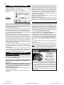
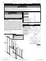
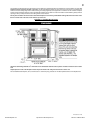
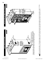
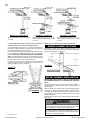
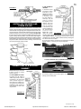
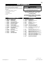
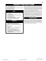
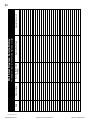
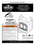
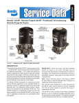
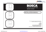
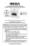
INSTALLER: LEAVE THIS MANUAL WITH THE APPLIANCE.
CONSUMER: RETAIN THIS MANUAL FOR FUTURE REFERENCE.
1
INSTALLATION AND
OPERATING INSTRUCTIONS
THIS FIREPLACE HAS BEEN TESTED AND LISTED BY INTERTEK TESTING SERVICES TO STANDARDS: CAN/ULC S610, UL 127, FOR ZERO CLEARANCE FIREPLACES, AND TO ULC
S639 FOR STEEL LINER ASSEMBLIES FOR SOLID FUEL BURNING MASONRY FIREPLACES. CERTIFIED UNDER USA ENVIRONMENTAL PROTECTION AGENCY (E.P.A.) JULY 1990 AND
THE OREGON DEPARTMENT OF ENVIRONMENTAL QUALITY (D.E.Q.) PARTICULATE EMISSION STANDARDS
NZ-26
SAFETY INFORMATION
!
WARNING
If the information in these instructions is not followed
exactly, a fire or explosion may result causing property
damage, personal injury or death.
Improper installation, adjustment, alteration, service or
maintenance can cause injury or property damage, bodily
injury or even death. Please read entire manual before you
install and use your fireplace.
This fireplace has not been tested with an unvented gas
log set. To reduce risk of fire or injury, do not install an
unvented gas log set into the fireplace.
- This fireplace can be very hot when burning.
- Combustible materials such as firewood, wet clothing, etc.
placed too close can catch fire.
- Children and pets must be kept from touching the fireplace
when it is hot.
- The chimney must be sound and free of cracks. Before installing this unit, contact the local building or fire authority and follow
their guidelines.
- Operate only with the door tightly closed.
- Burn wood behind the log retainer directly on the firebricks.
- Do not use an elevated grate or otherwise raise the fire.
- This fireplace is designed to burn natural wood only. Higher
efficiencies and lower emissions generally result when burning
air dried seasoned hardwoods, as compared to softwoods or to
green or freshly cut hardwoods.
- Do not start a fire with chemicals or fluids such as gasoline,
engine oil, etc.
- Do not burn treated wood, coal, charcoal, colored paper, cardboard, solvents or garbage.
- Do not let the fireplace become hot enough for any part to
glow red.
Wolf Steel Ltd., 24 Napoleon Rd., Barrie, ON, L4M 4Y8 Canada / 103 Miller Drive, Crittenden, Kentucky, USA, 41030
(705)721-1212 • fax(705)722-6031 • www.napoleonfireplaces.com • [email protected]
W415-0676 / 03.14.08
W415-0676 / 03.14.08
$10.00
NorthlineExpress.com
http://www.northlineexpress.com
Toll-Free 1-866-667-8454
2
INTRODUCTION
! WARNINGS AND SAFETY PRECAUTIONS
W415-0676 / 03.14.08
NorthlineExpress.com
http://www.northlineexpress.com
Toll-Free 1-866-667-8454
3
TABLE of CONTENTS
PG 2-6
INTRODUCTION
16
16
Warnings and Safety Precautions
Specifications
Warranty
Installation Overview
General Instructions
General Information
Care of Glass and Plated Parts
7
Controlling Combustion Air
Achieving Proper Draft
17-18 OPERATING INSTRUCTIONS
Fuel Loading and Burn Cycle
Ash Removal Procedures
HI-EFFICIENCY HEATING
Five Options
18
Location and Clearances
Framing
Finishing
Enclosure Finishing and Enclosure Alternate Finishing
Outside Combustion Air
Mantel Clearances
Hearth Extension
19-20
REPLACEMENTS
Ordering Replacement Parts
Replacement Parts
Accessories
11-13 CHIMNEY INSTALLATION
14-15 FINAL ASSEMBLY
MAINTENANCE
Gasket / Baffle Replacement
Door Glass Replacement
Creosote Formation And Removal
Run-Away or Chimney Fire
Fire Extinguishers and Smoke Detectors
Woodpile Maintenance
8-11 INSTALLATION / FRAMING
Adding Chimney Sections
Offset Chimney Installation
Installing Flashing and Storm Collar
Connection to a Masonry Chimney
OPTIONAL BLOWER
FEATURES
21
TROUBLE SHOOTING
22
SERVICE HISTORY
23-24 NOTES
Attaching the Handle
Top Firebrick and Baffle Installation
NOTE: Changes, other than editorial, are denoted by a vertical line in the margin.
Congratulations on the purchase of your hi-tech, high efficiency solid fuel burning fireplace! It has been extensively tested
in Canadian and American laboratories.
SPECIFICATIONS
FIGURE 1
W415-0676 / 03.14.08
NorthlineExpress.com
http://www.northlineexpress.com
Toll-Free 1-866-667-8454
4
N A P O L E O N ® p r o d u c t s a r e m a n u fa c t u r e d u n d e r t h e s t r i c t S t a n d a rd o f t h e Wo r l d R e c o g n i z e d
ISO 9001 : 2000 Quality Assurance Certificate.
NAPOLEON® products are designed with superior components and materials, assembled by trained craftsmen who take great
pride in their work. The complete fireplace is thoroughly inspected by a qualified technician before packaging to ensure that you,
the customer, receives the quality product that you expect from NAPOLEON®.
NAPOLEON® WOOD FIREPLACE PRESIDENT'S LIFETIME LIMITED WARRANTY
The following materials and workmanship in your new NAPOLEON® wood fireplace are warranted against defects for
as long as you own the fireplace. This covers: combustion chamber, heat exchanger, stainless steel baffle retainer, ceramic
glass (thermal breakage only), gold plated parts against tarnishing, porcelainized enamelled components, aluminum extrusion
trims ash drawer, and cast iron castings.
Electrical (110V) components and wearable parts such as blowers, thermal switch, switches, wiring, firebrick, gasketing, and
high temperature paint are covered and NAPOLEON® will provide replacement parts free of charge during the first year
of the limited warranty.
Labour related to warranty repair is covered free of charge during the first year. Repair work, however, requires the prior
approval of an authorized company official. Labour costs to the account of NAPOLEON® are based on a predetermined rate
schedule and any repair work must be done through an authorized NAPOLEON® dealer.
CONDITIONS AND LIMITATIONS
NAPOLEON® warrants its products against manufacturing defects to the original purchaser only -- i.e., the individual or legal entity
(registered customer) whose name appears on the warranty registration card filed with NAPOLEON® -- provided that the purchase was
made through an authorized NAPOLEON® dealer and is subject to the following conditions and limitations:
This factory warranty is non-transferable and may not be extended whatsoever by any of our representatives.
The wood fireplace must be installed by an authorized service technician or contractor. Installation must be done in accordance with
the installation instructions included with the product and all local and national building and fire codes.
This limited warranty does not cover damages caused by misuse, lack of maintenance, accident, alterations, abuse or neglect and
parts installed from other manufacturers will nullify this warranty.
This limited warranty further does not cover any scratches, dents, corrosion or discoloring caused by excessive heat, abrasive and
chemical cleaners nor chipping on porcelain enamel parts, nor any venting components used in the installation of the fireplace.
In the first year only, this warranty extends to the repair or replacement of warranted parts which are defective in material or workmanship
provided that the product has been operated in accordance with the operation instructions and under normal conditions.
After the first year, with respect to the President's Limited Lifetime Warranty, NAPOLEON® may, at its discretion, fully discharge all
obligations with respect to this warranty by refunding to the original warranted purchaser the wholesale price of any warranted but
defective part(s).
After the first year, NAPOLEON® will not be responsible for installation, labour or any other costs or expenses related to the reinstallation
of a warranted part, and such expenses are not covered by this warranty.
Notwithstanding any provisions contained in the President's Limited Lifetime Warranty, NAPOLEON’S responsibility under this warranty
is defined as above and it shall not in any event extend to any incidental, consequential or indirect damages.
This warranty defines the obligations and liability of NAPOLEON® with respect to the NAPOLEON® wood fireplace and any other
warranties expressed or implied with respect to this product, its components or accessories are excluded.
NAPOLEON® neither assumes, nor authorizes any third party to assume, on its behalf, any other liabilities with respect to the sale
of this product. NAPOLEON® will not be responsible for: over-firing, downdrafts, spillage caused by environmental conditions such as
rooftops, buildings, nearby trees, hills, mountains, inadequate vents or ventilation, excessive venting configurations, insufficient makeup
air, or negative air pressures which may or may not be caused by mechanical systems such as exhaust fans, furnaces, clothes dryers,
etc.
Any damages to fireplace, combustion chamber, heat exchanger, brass trim or other component due to water, weather damage, long
periods of dampness, condensation, damaging chemicals or cleaners will not be the responsibility of NAPOLEON®.
The bill of sale or copy will be required together with a serial number and a model number when making any warranty claims from
your authorized dealer. The warranty registration card must be returned within fourteen days to register the warranty.
NAPOLEON® reserves the right to have its representative inspect any product or part thereof prior to honouring any warranty
claim.
ALL SPECIFICATIONS AND DESIGNS ARE SUBJECT TO CHANGE WITHOUT PRIOR NOTICE DUE TO ON-GOING PRODUCT IMPROVEMENTS. NAPOLEON® IS A
REGISTERED TRADEMARK OF WOLF STEEL LTD. PATENTS U.S. 5.303.693.801 - CAN. 2.073.411, 2.082.915. © WOLF STEEL LTD.
W415-0676 / 03.14.08
NorthlineExpress.com
http://www.northlineexpress.com
Toll-Free 1-866-667-8454
5
INSTALLATION OVERVIEW
FIGURE 2
!
WARNING
This fireplace and its components are designed to be installed and
operated as a system. Any alteration to or substitution for items in
this system, unless allowed by these installation instructions, will
void the Warnock Hersey, listing and may void the product warranty. It may also create a hazardous installation. Read through
these instructions thoroughly before starting your installation and
follow them carefully throughout your project.
W415-0676 / 03.14.08
NorthlineExpress.com
http://www.northlineexpress.com
Toll-Free 1-866-667-8454
6
GENERAL INSTRUCTIONS
This is the most efficient,
simple and trouble free
woodburning system
we know of and works
as follows:
FIGURE 3
Your fireplace must be installed in accordance with all national and local
building code standards and the standard of Chimney and Fireplaces,
Vents and Solid Fuel Burning Appliances NFPA #211. Consult the
authority having jurisdiction (such as municipal building department,
fire department, fire prevention bureau, etc.) to determine the need
to obtain a permit. If you are in doubt about the proper installation for
your situation, contact your dealer or local building or fire official. The
manufacturer does not guarantee that this fireplace and its options will
completely heat your entire home.
Expansion / contraction noises during heating up and cooling down
cycles are normal and to be expected.
Mobile home installation requires that the fireplace be secured
to the floor. It is recommended that in all cases, the fireplace be
secured to the floor. Use the pallet packing brackets to accomplish
this.
CARE OF GLASS AND PLATED PARTS
Primary combustion air enters through the air control inlet box regulated
by a draft control, travels up the side through a duct and enters the top
centre of the combustion chamber into a preheating airwash located
across the top and then down the window to feed the fire and also to
ensure that the glass remains clean.
Secondary air feeds directly into the combustion chamber at hearth level
through the log retainer and also through inlets located at the bottom
back corners of the combustion chamber. This air travels up the riser
to the four secondary air tubes located at the top and shoots out laterally
to oxidize the gases rising to the smoke exit.
The combustion chamber is lined with high-temperature firebrick on
all sides, and across the bottom to maintain a high temperature in the
combustion chamber so that gases mixing with the preheated air from
the secondary air tubes are easily ignited and burned. The fireplace
sides and back permit a zero clearance installation and direct the
heat upwards and forwards into the room. Be sure to provide sufficient combustion air. There are many other appliances in your home
competing for air such as a kitchen range hood, forced air heating
devices or a bathroom exhaust fan.
If the outside air feature is utilized, you will never experience a
shortage of combustion air. If you choose not to utilize outside air
and experience draft or smoking problems, you may need to open
a door or window.
After extended periods of non-operation such as following a vacation
or a warm weather season, the fireplace may emit a slight odour for
a few hours. This is caused by dust particles on the firebox burning
off. Open a window to sufficiently ventilate the room.
If the glass is not kept clean permanent discoloration and / or blemishes may result. Normally a hot fire will clean the glass. The most
common reasons for dirty glass include: not using sufficient fuel to
get the stove thoroughly hot, using green or wet wood, closing the
draft so far that there is insufficient air for complete combustion. If it
is necessary to clean the glass, use a soft cloth with a non-abrasive
cleaner. Do not clean the glass when hot!
The glass is very strong but do not let burning fuel rest or fall against it
and always close the door gently. Never force it shut!
If the glass should ever crack while the fire is burning, do not open the
door until the fire is out and do not operate the stove again until the glass
has been replaced with a new 5mm thick piece of ceramic glass, available
from your authorized dealer. Do not substitute materials.
For information on glass removal and replacement, see Maintenance.
Do not use abrasive cleaners to clean plated parts. Buff lightly with a
clean dry cloth.
Prolonged high temperature burning with the door ajar may cause a
permanent rainbowing effect on the lower edge of a gold plated door.
NOTE: The protective wrap on plated parts is best removed when
the assembly is at room temperature but this can be improved if the
assembly is warmed, using a hair dryer or similar heat source.
GENERAL INFORMATION
CALIFORNIA PROP 65 WARNING:
Use of this product may produce smoke which contains chemicals known to the State of California to cause cancer, birth
defects, or other reproductive harm.
Do not use makeshift compromises during installation. Do
not block or restrict air, grille or louvre openings! Do not
add a hood.
Burning your unit with the ash dump door open or ajar
creates a fire hazard that may result in discoloration to
the gold plated door, internal damage to the fireplace or
a house and/or chimney fire.
All venting connections must be in compliance with the chimney manufacturers installation instructions.
Clearances referred to throughout this manual are the minimum requirements.
When the appliance is equipped with a 24 karat gold-plated door,
you must clean all the fingerprints and oils from the gold surface
before firing the appliance for the first time. Use a glass cleaner
or vinegar and towel to remove the oils. If not cleaned properly
before lighting your first fire, the oils can cause permanent markings on the gold plating. After the gold plating is cured, the oils will
not affect the finish and little maintenance is required, just wipe
clean as needed.
W415-0676 / 03.14.08
NorthlineExpress.com
http://www.northlineexpress.com
Toll-Free 1-866-667-8454
7
HI-EFFICIENCY HEATING
FIVE OPTIONS
To operate this hi-efficiency fireplace as a basic system, the blower
is not required, however, to enhance its efficiency a blower is recommended.
ATTIC
A BLOWER KIT (NZ62) This blower is installed in the bottom of the unit
and used to direct the heat into the room where the fireplace is located. The blower is controlled, by a variable speed switch, located
inside the fireplace.
BLOWER
LOCATION
OPTIONS
OPTION
FOR
TYING
INTO
EXISTING
DUCT
WORK
A THERMOSTATIC AIR CONTROL (NZ690KT) may be used for constant
heat, complete with automatic damper and thermostat, wall mounted
in the room containing the fireplace, and at least 10 feet (minimum)
from the fireplace.
A HOT AIR GRAVITY VENT SYSTEM (NZ220) may be used to distribute
heat to an adjoining room (located either above, or beside the room
containing the fireplace) by way of vents, eliminating the need of
an additional blower. While this system may be used in conjunction
with the optional blowers, it could reduce the flow of hot air being
distributed to additional rooms. It must be experimented with and
the dampers adjusted manually to suit your requirements. This
may take a few attempts; thereafter adjustments should no longer
be required as is normally experienced with your central heating
system registers.
The heat shield cover plate must be removed before installing
the gravity vent. The hot air vent must be installed in an upward
direction! NEVER install in a downward direction. Figure 6. The
hot air gravity vent system is not to be connected to a central
heating system (for this application use the NZ62CH). This
option may not be used in mobile homes.
No more than two hot air gravity vents can be installed to fireplace.
Individual vent runs are not to exceed 10 feet.
All hot air gravity vents must be insulated.
FIGURE 5b
A HOT AIR DISTRIBUTION KIT (GA-566) may be used to distribute warm
air from the fireplace base (only) into a separate location in the
home.
These options may be incorporated with one another. If the optional
blowers are to be installed, make provision during framing to route a
110 volt power line to the fireplace. Detailed installation instructions
are included with each venting kit.
NO
DUCTING
GRAVITY VENT
OPTION (1 DUCT)
GRAVITY VENT
OPTION (2 DUCTS)
GRAVITY VENT OPTION
*
CENTRAL HEATING
CENTRAL HEATING
BOTTOM
CENTRAL HEATING
RIGHT SIDE
ONLY
CENTRAL HEATING &
GRAVITY VENT OPTION
HEAT SHIELD COVER PLATE
* MASONRY APPLICATION ONLY
!
STOVE TOP
FIGURE 4
A CENTRAL HEATING SYSTEM (NZ62CH) may be used to heat rooms up to
50 feet from the unit. A wall mounted thermostat located in the room
to be heated controls the blower supplying warm air from the room
containing the fireplace. If a hot air duct system exists, the central
heat blower may safely be tied into this system to reduce the amount
of new ducting required. Consult with a heating specialist to ensure
a proper duct layout for your home. If the NZ62CH is installed at the
bottom of the unit, it could introduce a cool draft into the room that
the fireplace is installed in.
When attached to the top or sides of the unit, it provides a higher heat
output. This option may not be used in mobile homes.
FIGURE 6
WARNING
Do not draw outside air from garage spaces. Exhaust products of
gasoline engines are hazardous.
Do not install outside air ducts such that the air my be drawn from
attic spaces, basements or above the roofing where other heating appliances or fans and chimneys exhaust or utilize air. These
precautions will reduce the possibility of fireplace smoking or air
flow reversal. The outside air inlet must remain clear of leaves,
debris ice and/or snow. It must be unrestricted while unit is in use
to prevent room air starvation which can cause smoke spillage
and an inability to maintain a fire. Smoke spillage can also set off
smoke alarms.
To prevent contact with sagging or loose insulation, the fireplace
must not be installed against vapour barriers or exposed insulation.
Localized overheating could occur and a fire could result.
FIGURE 5a
W415-0676 / 03.14.08
NorthlineExpress.com
http://www.northlineexpress.com
Toll-Free 1-866-667-8454
8
INSTALLATION / FRAMING
!
WARNING
Before starting, do the following:
1. For protection wear gloves and safety glasses.
2. Keep hand tools in good condition, sharpen cutting edges and make sure tool handles are secure.
3. Always maintain the minimum air space required to the enclosure to prevent fires.
!
MAINTAIN THESE MINIMUM CLEARANCES TO
COMBUSTIBLES:
Fireplace framing:
Top Stand-Off
0"
Rear Stand-Off
0"
Side
6"
Fireplace finishing:
Sides
63/4"
Top
63/4"
Factory Built Chimney
2"
Hot Air Gravity Ductwork Insulation
1"
*Base of unit to ceiling
72"
72"
*Base of unit to enclosure top
Enclosure must have ventilation
between 72" and 84"
WARNING
Carefully follow the instructions for assembly of the chimney and other
parts needed to install this fireplace. Failure to do so may result in a fire,
especially if combustibles are too close to the fireplace or chimney and
air spaces are blocked, preventing the free movement of cooling air.
LOCATION AND CLEARANCES
Do not build shelves or cupboards into the area above
the fireplace.
While the fireplace can be installed directly on the floor, a noncombustible hearth extension is required in front of the fireplace,
that must not be built higher than the bottom of the fireplace to
avoid air flow blockage. It may therefore be advisable to build the
fireplace on a raised platform. The minimum distance between the
edge of the fireplace and any adjacent wall, at right angles to it, is
21". A wall projecting at 45° from the outer edge of the fireplace is
allowed; projections into this area are permitted. Do not install into
any area having a height less than 6 feet (ceiling to fireplace base,
excluding hearth height). See Section on Framing. The location of
windows, doors and the traffic flow in the room where the stove is
to be located should be considered. If possible, you should choose
a location where the chimney will pass through the house without
cutting a floor or roof joist.
FIGURE 7a: Framing Requirements
!
WARNING
*84" if installing optional hot air gravity vent system, NZ220 on the
same floor as the fireplace.
FRAMING
NOTE: In order to avoid the possibility of exposed insulation or vapour
barrier coming in contact with the
fireplace body, it is recommended
that the walls of the fireplace
enclosure be “finished”
(i.e.: drywall/sheetrock),
as you would finish any
other outside wall of a
home. This will ensure
that clearance to combustibles is maintained
within the cavity.
NOTE: Do not build into this area - it must
be left clear to provide adequate clearance
for the vent in this 14” wide area centered
along the front of the fireplace. No combustibles are allowed.
3 1/2” MAX
72”
MINIMUM
ENCLOSURE
HEIGHT
FIGURE 7b
14” MAX
1 1/2”
MAX
25 3/4”
44 3/4”
50 3/4”
W415-0676 / 03.14.08
NorthlineExpress.com
http://www.northlineexpress.com
Toll-Free 1-866-667-8454
9
The fireplace should be framed using 2x4 lumber. For the header and cripple studs above the fireplace it is recommended to use steel. The
fireplace must be secured to the floor in all cases. Use the pallet packing brackets to secure to the floor. If ducting is to be installed, the
minimum enclosure ceiling height is 84". Without ducting, the ceiling height may be brought down to a minimum of 72". However a fireplace
enclosure with a height less than 84" must be provided with sufficient air circulation to avoid a fire hazard. Install ventilation grilles (minimum
openings of 40 sq. inches) at both floor and ceiling levels of the enclosure.
Do not place insulation into the enclosure around the fireplace or the chimney. Combustible framing materials must not be closer
than 6" from the side of the unit and 5" from the top of the unit.
FIGURE 7c: Finishing Requirements
FINISHING
Clearances to finishing materials: 6 3/4" minimum of non-combustible material to the top of the unit and a minimum 6 3/4" to either
side.
Objects placed in front of the fireplace must be kept a minimum of 48" away from the front face of the unit.
Non-combustible material (brick, stone, cement board or ceramic tile) may protrude over the black painted surface of the fireplace front.
W415-0676 / 03.14.08
NorthlineExpress.com
http://www.northlineexpress.com
Toll-Free 1-866-667-8454
NorthlineExpress.com
http://www.northlineexpress.com
12”
MAXIMUM
FIGURE 8a
1” OPEN
VENTILATION
REQUIRED IN
ENCLOSURES
BETWEEN 72”
AND 84”
72” MINIMUM
ENCLOSURE
HEIGHT
1” OPEN
FIGURE 8b
ENCLOSURE ALTERNATE FINISHING
NOTE: As an alternate to grates a 1" x 40 inches wide gap can be left in the bottom and top of any finishing material to circulate the air from the floor, around the fireplace
through the enclosure and out the top. If utilizing this method, ensure the fireplace is properly supported and support method does not restrict the flow of air.
Minimum 40 square inches of
ventilation opening required, both at
the top and bottom of the enclosure. Ventilation openings are required in
enclosures up to 84” high. They are recommended for all enclosures.
VENTILATION
REQUIRED IN
ENCLOSURES
BETWEEN 72”
AND 84”
72” MINIMUM
ENCLOSURE
HEIGHT
12”
MAXIMUM
ENCLOSURE FINISHING
10
W415-0676 / 03.14.08
Toll-Free 1-866-667-8454
11
OUTSIDE COMBUSTION AIR
Model NZ-26 has the option of taking outside air directly into the
fireplace through the opening on the left hand side or taking inside
air through the lower front louvres or a combination of both.
If the optional fresh air kit (available through your authorized dealer)
is installed, it must not draw air from the attic or garage. It may only
come from outside the house. The maximum length of the 4" air duct
is 20 feet; thereafter enlarge the duct to a 6" diameter.
Decide on the most convenient location for the fresh air inlet duct and
hood which may be installed above or below floor level.
Make a 5" hole in an outside wall of the house. From outside, place
the fresh air hood into the hole, open side down.
At each end, carefully pull back the insulation sleeve exposing the
flexible duct. Place the insulated flexible duct over the fresh air hood
and over the fireplace outside air connector. Carefully push the insulation sleeve back over the duct. Using the clamps, fasten the insulated
duct into place on both sides. Figure 9.
For outside air only, re-install the inside air cover plate, shown in
Figure 37, to cover the control box inside air opening. See Section
on Combustion Air Control.
A chimney venting the fireplace shall not vent any other appliance.
A chimney venting the fireplace shall not vent any other appliance.
MANTEL CLEARANCES
Mantel clearance can
vary according to the
mantel depth.
FIGURE 10
HEARTH EXTENSION
An acceptable 16" x 50" non-combustible (i.e.: brick, stone or ceramic
tile) hearth extension must be installed. Ensure that the gap between
the fireplace and a factory-built hearth extension is sealed with sand/
cement grout or covered with a metal strip (or both) to prevent sparks
and embers from falling into this area. A raised hearth together with
the fireplace built on a raised platform is recommended for easier
wood loading and fire viewing.
!
FIGURE 9
WARNING
Hearth extensions are to be installed only as described to prevent
high temperatures from occurring on concealed combustible materials. Hearth sealing strips prevent burning or hot particles from
inadvertently falling directly on combustible surfaces in the event
the building should settle and disturb the original construction.
CHIMNEY INSTALLATION
!
If the chimney system is enclosed within the attic area, a rafter radiation shield is required.
WARNING
Never install a single wall slip section or smokepipe in a chase
structure. The higher temperature of this single wall pipe may
radiate sufficient heat to combustible chase materials to cause
a fire.
To avoid danger of fire, all instructions must be strictly followed,
including the provision of air space clearance between chimney
system and enclosure. To protect against the effects of corrosion
on those parts exposed to the weather, we recommend that the
chase top be painted with a rust-resistant paint.
Maintain a minimum 2" air clearance to all parts of the chimney
system at all times. Failure to maintain this 2" air clearance will
cause a structure fire.
Detailed instructions for installation of the chase top, storm collar
and termination cap are packaged with these parts.
Firestop spacers must be used whenever the chimney penetrates
a ceiling/floor area.
A chimney venting the fireplace shall not vent any other appliance.
The minimum overall chimney height from the top of the fireplace
is 11 feet.
The maximum overall chimney height from the top of the fireplace
is 34 feet.
Factory-built chimney systems for use in dwellings constructed for
three or more families must be enclosed above the room in which
the fireplace is located. This enclosure must have a fire resistance
rating equal to or greater than that of the floor or roof assembly
through which they pass.
The chimney must extend at least 3 feet above its point of contact
with the roof and at least 2 feet higher than any wall, roof or building
within 10 feet.
If the chimney extends more than 5 feet above the roof, it must be
secured using a roof brace or guide wires.
Ensure that minimum clearances are maintained
Portions of the chimney that extend through accessible spaces must
always be encased to avoid personal contact with the chimney and
thereby avoid damage to the chimney.
A raincap must be installed to avoid internal damage and corrosion.
The chimney must be supported at a maximum of 20 foot intervals
(approx. 200 lbs/20 ft).
The NZ-26 was tested to CAN/ULC S610 and UL 127 Factory Built
Fireplace Standards. This fireplaces has met the test criteria for
Zero Clearance Installation to Combustible Surfaces and Certified
to burn Firewood only.
Any 6" diameter chimney listed to these standards may be installed.
In accordance with these standards, the unit may also be connected
to any chimney listed to CAN/ULC-S609 and ULC-S629 for Canada
or UL-103HT for the United States.
Installation of all types of factory-built chimney systems is to be in
accordance with the chimney manufacturers installation instructions.
An appropriate chimney manufacturers anchor base plate and anchor
base plate gasket is required in order to initiate the twist lock mechanism. Use the high temperature gasket, supplied, to seal between
the anchor plate and the fireplace top.
W415-0676 / 03.14.08
NorthlineExpress.com
http://www.northlineexpress.com
Toll-Free 1-866-667-8454
12
FIGURE 11 - STRAIGHT UP
FIGURE 12 - 2 ELBOWS
FIGURE 13 - 4 ELBOWS
No Off-Set. Minimum overall chimney height
is 11 feet.
Single off-set with two 15°, 30° or 45°
elbows. Minimum overall chimney height
is 11 feet.
Double off-set with four 15°, 30° or 45°
elbows. Minimum overall chimney height
is 11 feet.
* The first flue offset closest to the top of the unit must be a
minimum distance of 12" from the top of the fireplace.
1. Move the fireplace into position. Try to centre the exhaust flue of
the fireplace, midpoint between two joists to prevent having to cut
them. Use a plumb bob to line up the centre.
2. Cut and frame an opening in the ceiling to provide a minimum clearance of 2" between the outside of the chimney and any combustible
material. DO NOT FILL THIS SPACE WITH ANY TYPE OF MATERIAL! Nail headers between the joists for extra support. Firestop
spacers must be placed on the bottom of each framed opening in
any floor or ceiling that the chimney passes through.
3. Hold a plumb bob from the underside of the roof to determine
where the opening in the roof should be. Cut and frame the roof
opening maintaining proper 2" clearances.
NOTE: 30° or 45° offsets may be installed back to back.
ADDING CHIMNEY SECTIONS
Add chimney sections, twist locking (clockwise) securely, to the
required height. Use a rafter radiation shield whenever the chimney
system is enclosed within an attic area.
FIGURE 16
FIGURE 14
OFFSET CHIMNEY INSTALLATION
FIGURE 15
The first flue offset closest to the top of the unit must
be a minimum distance of 12" from the top of the fireplace.
An insulated elbow must be used when it becomes necessary to
offset the chimney in order to clear a joist or to pass through an
upstairs closet.
Attach an elbow to the chimney section, angled toward the offset.
Secure with 3 - #8X1/2" sheet metal screws. To achieve the minimum offset, attach and secure a return elbow to the first. To achieve
longer offsets, you may install any available length of chimney pipe
between the elbows.
Supports must be used on the first vertical chimney section after a
return elbow.
!
WARNING
Chimney sections installed between an offset and return require
structural support to reduce off-center loading and to prevent
chimney sections from separating at the chimney joints.
The chimney should not be built with an offset angle in excess of
45° in Canada and 30° in USA. Do not combine offset chimney
components to exceed these angles.
W415-0676 / 03.14.08
NorthlineExpress.com
http://www.northlineexpress.com
Toll-Free 1-866-667-8454
13
IF THE CHIMNEY IS
UNLINED:
FIGURE 17
INSTALLING FLASHING AND
STORM COLLAR
Remove the nails from the shingles above and to the sides of the
chimney. Place the flashing over the chimney pipe and slide underneath the sides and upper edge of the shingles. Ensure that the chimney pipe is properly centered within the flashing, giving a 3/4" margin
all around. Fasten to the roof on the top and sides. DO NOT NAIL
through the lower portion of the flashing. Make weather-tight by sealing with caulking. Where possible, cover the sides and top edges of
the flashing with roofing material. Apply waterproof caulking, provided
with the flashing, around the chimney, 1" above the top of the flashing
and push the storm collar down into the caulking. Insert a rain cap
onto the top of the last chimney section.
A stainless steel
liner listed to either
Standard ULCS640M, ULC-S639 in
Canada or UL-1777
in the USA: Liners
for New Masonry
Chimneys, may be
used to connect
the fireplace to the
chimney. The liner
must be continuous
from the fireplace
to the chimney cap
and be installed only
per manufacturers
instructions.
Figure 19. In both
FIGURE 20
cases, the chimney
structure must be supported by angle iron anchored into the masonry
walls. Figures 19 & 20. The allowable masonry used in chimney
construction is 3-1/2" brick, solidly mortared and fully encasing the
flue. Ensure there are no leaks.
In no case is the masonry enclosure to be supported by the NZ-26
fireplace. Allow a 1" (one inch) air cavity for expansion.
FIGURE 18
ANCHOR PLATE
HI-TEMP GASKET
FIREPLACE TOP
FIGURE 21
FLUE TILE SUPPORT FOR A MASONRY FIREPLACE
CONNECTION TO A MASONRY
CHIMNEY
Model NZ-26 may be connected
to either a lined or unlined
masonry chimney.
IF THE CHIMNEY IS LINED,
the flues must be made of
vitrified clay and be in sizes of
8" square, 8" x 12", or 8" round
with a minimum height of 11
feet above the fireplace. 8"
round flues are recommended.
Installation must conform to
both national and local code
requirements.
HI-TEMP GASKET
FIREPLACE TOP
FIGURE 22
For a masonry fireplace use a flue tile support. For a pre-fabricated
chimney use an anchor plate.
FIGURE 19
W415-0676 / 03.14.08
NorthlineExpress.com
http://www.northlineexpress.com
Toll-Free 1-866-667-8454
14
FINAL ASSEMBLY
ATTACHING THE HANDLE
Attach the handle as shown so that
when the door is closed, the handle
will be centred in the slot located on the
fireplace front. To achieve this you may
have to experiment (on the upper and
lower screws) with one of the variations
shown. Tighten securely.
TOP FLAME SPREADER
BOTTOM FLAME SPREADER
FIBRE BAFFLE (1 OF 2 SHOWN)
TOP FIREBRICK (1 OF 2 SHOWN)
FIGURE 23
FIGURE 24
FIGURE 28
3a
!
FIGURE 25
TOP FIREBRICK AND BAFFLE
INSTALLATION
WARNING
Operation of the fireplace without the top firebricks and the
baffles can result in excessive temperatures that could damage the fireplace, chimney and the surrounding enclosure.
The fireplace is shipped with the firebricks in place. Top firebricks,
fibre baffles and gasket rope are not installed.
BAFFLE SUPPORT BRACKET
FIBRE BAFFLE
TOP FIREBRICK
TUBE
TUBE
RETAINER
FIGURE 26
1
1
Unscrew and remove the front tube retainer. Note that the first
tube retainer also holds the side brick in place. Slide the tube
either to the left or right and remove. Remove the two middle
tubes in the same fashion.
1
3b
FIGURE 29
Insert the left baffle, then the left top firebrick. Repeat using
the right baffle and brick.
The baffles are made of a brittle material. Care must be taken
not to bend or force them.
Replace the three front tubes. Position the center edges of both baffles and bricks until they lie snugly together.
Slide the baffle support bracket into place along the front of the unit
between the front tube and the two top firebricks.
3
REAR
BRICKS
GASKET ROPE LOCATION
2
2
FIGURE 27
Place gasket rope along the upper ledge of the air chamber
and on the top of the rear bricks. The top and bottom flame
spreaders come taped together. This tape will burn away in the initial
firing of the unit. On subsequent brick removals, the bottom flame
spreader must be taped to the top spreader to ease top brick and
baffle removal and to avoid damaging the fibre baffles.
4
FIGURE 30
W415-0676 / 03.14.08
NorthlineExpress.com
http://www.northlineexpress.com
Toll-Free 1-866-667-8454
15
If you need to remove the bricks (to lighten the fireplace for ease of
installation, replacement, etc), follow this sequence:
For Firebrick Removal: Remove the ashwell grate. This allows
the four bottom bricks to be removed first.
Slide out the baffle support bracket from above the front tube.
Reaching above the top firebricks and baffles, lift and tape the bottom flame spreader to the top spreader to ease top brick and baffle
removal and to avoid damaging the fibre baffle. Remove the three
front tubes.
Remove the top firebrick on the right, then the left firebrick. Remove
the baffles, starting with the right side.
Remove the gasket rope. Check the rope for deterioration and replace
if necessary. Remove the rear bricks (pull the two bricks forward at
the centre, and lift the bottom of the bricks out). Remove the side
bricks (tilt the tops inward).
4
FIGURE 31
TOP FLAME SPREADER
BOTTOM FLAME SPREADER
FIBRE BAFFLES
TOP FIBREBRICKS
BAFFLE SUPPORT
TUBE BURNERS
GASKET
GASKET
LEFT SIDE FIBREBRICK REAR FIBREBRICKS RIGHT SIDE FIBREBRICK
BOTTOM LEFT FIBREBRICK
BOTTOM RIGHT FIBREBRICK
LEFT FRONT FIBREBRICK
RIGHT FRONT FIBREBRICK
W415-0676 / 03.14.08
NorthlineExpress.com
http://www.northlineexpress.com
Toll-Free 1-866-667-8454
16
OPTIONAL BLOWER INSTALLATION
WARNING
!
INSTALLATION TO BE DONE BY A QUALIFIED INSTALLER and must be electrically connected and grounded in accordance with local codes.
In the absence of local codes, use the current CSA C22.1 CANADIAN ELECTRICAL CODE in Canada or the ANSI/NFPA 70 NATIONAL
ELECTRICAL CODE in the United States.
1. Turn off any electrical power to the fireplace (if applicable). Open the lower louvred
control door.
2. Locate the vibration reducing pad over the two threaded studs, piercing 2 holes into
the pad. The fan must be installed on the left hand side of the fireplace entirely on the pad.
3. Slide the fan to the back of the fireplace taking care not to damage the terminals.
Position the fan onto the studs and secure using the lock washers and wing nuts provided.
Pull the leads to the front and right side of the ashpan housing.
4. Remove the junction box. Use a nut connector to attach the black wires of the variable
speed switch and the power.
5. Pass the two fan leads and one thermodisc lead through the junction box bushing.
FIGURE 32
The thermodisc is located inside the outer shell, just above the louvre door. Connect one fan
lead to the thermodisc lead and the other fan lead to the white wire of the variable speed
switch using nut connectors.
6. Thread the other thermodisc lead through the junction box bushing and connect to the white wire of the power cord using a nut
connector. Secure ground wire (green) to the threaded weld stud located on the junction box wall. Reposition the junction box. Verify that
the wires will not interfere with the fan.
BECAUSE THE BLOWER IS THERMALLY ACTIVATED, WHEN TURNED ON, IT WILL AUTOMATICALLY START APPROXIMATELY
15-45 MINUTES AFTER LIGHTING THE FIREPLACE. USE OF THE FAN INCREASES THE OUTPUT OF HEAT.
Drywall dust will penetrate into the blower bearings causing irreparable damage and must be prevented from coming into contact
with the blower or its compartment. Any damage resulting from this condition is not covered by the warranty policy.
FIGURE 33
BLOWER
WING NUT &
LOCK WASHER
VIBRATION
REDUCING PAD
THERMODISC
VARIABLE
SPEED
SWITCH
FAN
JUNCTION BOX
FEATURES
CONTROLLING COMBUSTION AIR
!
WARNING
Fireplace operation does require air. Do not take air from other fuel
burning appliances which can result in improper venting (smoking)
or air dilution. Always provide adequate makeup air.
If the outside combustion air kit is not used, air may still be drawn
directly into the fireplace through the lower louvres. Outside and
inside air may be combined by pulling the outside air lever out as far
as possible, and turning the lever 90° to its locking position.
Should you find a frost build up on
the air control box or a draft
from the fireplace, close the outside
air lever when the fireplace
is not in use.
Air control box
is shipped
with inside
air cover
plate in open
position.
ACHIEVING PROPER DRAFT
Draft is the force which moves air from the fireplace up through the
chimney. The amount of draft in your chimney depends on the length
of the chimney, local geography, nearby obstructions and other forces.
Adjusting the draft control regulates the temperature. The draft can
be adjusted from a low burn rate with the handle at the bottom setting
to a fast burn rate with the handle at the top setting. Inadequate draft
may cause back-puffing into the room and may cause plugging of
the chimney. Too much draft may cause an excessive temperature
in the fireplace, glowing red fireplace parts or an uncontrollable burn
which can all lead to a chimney fire or a permanent damage to the
unit. Do not operate your fireplace for longer than 30 minutes
with the draft control on 'HIGH' (fully
open).
FIGURE 34
W415-0676 / 03.14.08
NorthlineExpress.com
FIGURE 35
http://www.northlineexpress.com
Toll-Free 1-866-667-8454
17
OPERATING INSTRUCTIONS
Remove all source of gasoline or other flammable vapours and
liquids in the vicinity of this or other appliances prior to lighting. Ensure that the top firebricks and fibre baffles are in place
and not lifted up.
When first installed, the fireplace and the steel are cold and must
become hot before the fireplace will function well. During the break-in
period (the first 2 or 3 fires) create only small, hot fires using kindling;
this will allow the firebrick to cure. Do not be alarmed if small hairline
cracks develop in the firebrick. This is a normal occurrence and does
not pose a safety hazard. The paint may also smell a little for the
first few fires as it cures and you may wish to open a door or window
to alleviate the smell.
To start, a brisk fire is required. Place loosely crumpled paper on
the floor of the fireplace behind the log retainer and cover with dry
kindling. Open the draft control fully by moving the lever to "HIGH".
Light the paper and leave the door slightly ajar (one inch) until all
kindling is burning. To maintain a brisk fire, a hot coal bed must be
established and maintained.
Slowly add larger wood (2x4 size pieces). Lay the pieces lengthwise
from side to side in the hot coal bed with a shallow trench between,
so that the primary air can flow directly into this trench and ignite the
fuel above. When the fire seems to be at its peak, medium sized
logs may be added. Once these logs have caught fire, carefully
close the door.
Closing the door too quickly after refuelling will reduce the firebox temperature and result in an unsatisfactory burn.
Remember it is more efficient to burn medium sized wood, briskly,
and refuel frequently than to load the fireplace with large logs that
result in a smouldering, inefficient fire and dirty glass.
As soon as the door is closed, you will observe a change in the flame
pattern. The flames will get smaller and lazier because less oxygen
is getting into the combustion chamber. The flames, however, are
more efficient. The flames will remain lazy but become larger again
as soon as the firebricks have been heated thoroughly and the
chimney becomes heated and provides a good draft. At this point,
the roaring fire that you see when the door is opened is wastefully
drawing heated room air up the chimney -- certainly not desirable.
So always operate with the door fully closed once the medium sized
logs have caught fire.
You can now add larger pieces of wood and operate the fireplace
normally. Once the fireplace is entirely hot, it will burn very efficiently
with little smoke from the chimney. There will be a bed of orange
coals in the firebox and secondary flames flickering just below the
top of the firebox. You can safely fill the firebox with wood to the top
of the door.
Can't get the stove operating? Use more kindling and paper.
Assuming the chimney and vent are sized correctly and there is
sufficient combustion air, the lack of sufficiently dry quantities of
small kindling is the problem. Thumb size is a good gauge for small
kindling diameter.
Can't get heat out of the stove? One of two things may have happened. The fireplace door may have been closed prematurely and
the fireplace itself has not reached optimum temperature. Re-open
the door and/or draft control to re-establish a brisk fire. The other
problem may have been wet wood. The typical symptom is sizzling
wood and moisture being driven from the wood.
!
FUEL LOADING AND BURN CYCLE
For maximum efficiency, when the fireplace is thoroughly hot, load
it fully to the top of the door opening and burn at a medium low setting. The bricks will be nearly all white and the glass mostly clear.
The whiteness of the bricks and the cleanness of the glass are good
indicators of your operating efficiency.
Not enough heat is produced when only one or two pieces of wood
are burned. A minimum of three pieces are needed to encase a bed
of coals that sustains the fire. Loosely stacked wood burns quicker
than a tightly packed load.
Wood burns in cycles rather than giving a steady output of heat. It
is best to plan these cycles around your household routine so that
only enough coals are left to start the next load. In the evening, load
your fireplace, at least, a half-hour before bed to ensure the fire is hot
enough to close the draft control for an overnight burn.
Burn only dry seasoned wood. It produces more heat and less soot or
creosote. Do not burn ocean beach wood. Its salt content can produce
a metal eating acid. When refuelling open the door slowly to prevent
smoke spillage. Use a pair of long fireplace gloves when feeding the
fire. Keep a small steel shovel nearby to use as a poker and to remove
ashes. Do not store wood within 3 feet (1m) of the fireplace.
FLASH FIRES: A flash fire is a small fire burned quickly when you
don't need much heat. After your kindling has "caught", load at least
3 pieces of wood, stacked loosely. Burn with the draft control fully
open or closed only slightly.
EXTENDED FIRE: Load your larger pieces of wood compactly,
packed close enough to prevent the flames from penetrating it
completely. After approximately 30 minutes, depending on the size
of the load, close the draft control completely making sure that the
fire is not extinguished.
DO NOT OVERFIRE THE FIREPLACE! Overfiring can occur by:
a) burning large amounts of smaller wood pieces such as furniture
scraps, skids or treated wood; b) vigorously burning large loads of
wood with the draft control on "HIGH" (fully open) for long periods of
time (one or two hours).
!
WARNING
Do not store fuel within the clearance to combustibles, or in the
space required for re-fueling and ash removal.
Burning wet, unseasoned wood can cause excessive creosote
accumulation. When ignited it can cause a chimney fire that may
result in a serious house fire.
Never use gasoline-type lantern fuel, kerosene, charcoal lighter
fluid, or similar liquids to start or "freshen up" a fire in this fireplace.
Keep all such liquids well away from the fireplace.
WARNING
This fireplace has not been tested with any vented or unvented
gas log set. To reduce risk of fire or injury, do not install a vented
or unvented gas log set into fireplace.
Always operate this appliance with the door closed and latched
except during start-up and re-fueling.
Do not leave the fire unattended when the door is unlatched. Unstable firewood could fall out of the firebox creating a fire hazard
to your home.
W415-0676 / 03.14.08
NorthlineExpress.com
http://www.northlineexpress.com
Toll-Free 1-866-667-8454
18
ASH REMOVAL PROCEDURES
A bed of ashes approximately 1" deep should be left on the firebox
bottom to help maintain a hot charcoal bed. When the fire has burned
down and cooled, remove any excess ashes. To use your ash pan, pull
the ash dump handle forward to an open position. Rake the excess
ashes over the grate and into the ash pan. Close the ash well.
FIGURE 36
Never operate your fireplace with the ash well in an open position!
This creates a fire hazard that may result in a house/chimney fire,
internal damage to the stove or discoloration to the gold plated door
(plated finishes are not covered by the warranty). To ensure that
the ash well is fully closed, allow the door to snap shut, dislodging
anything that may be stuck at the opening.
Flip the cover up onto the ash pan when transporting the ashes to
a closed container with a tight fitting lid for storage. Carry the ash
pan using the front and back handles. Keep the closed container on
a non-combustible floor or ground, well away from all combustible
materials. The ashes should be retained in the closed container until
all cinders have thoroughly cooled. Cold wood ashes can be used
on the garden or compost.
MAINTENANCE
GASKET / BAFFLE REPLACEMENT
At the end of each burning season inspect the baffle located above
the secondary air tubes for deterioration. Replace if necessary. At this
time also check that the door gasket is not worn or loose. Replace
with 1/2" fibreglass rope if necessary.
DOOR GLASS REPLACEMENT
To remove the door, open and lift out; remove the screws and brackets
holding the glass in place. Remove all broken glass. Wrap the edges
of the new glass with a U-shaped strip of fibreglass gasket, covering
1/4" on each side. Place this gasketed glass in position and replace the
brackets and screws. When finished, you should be able to move the
glass slightly, horizontally and vertically.
CREOSOTE FORMATION AND
REMOVAL
When wood is burned slowly, it produces tar and other organic
vapours which combine with expelled moisture to form creosote.
These vapours condense in the relatively cooler chimney flue of a
slow burning fire and when ignited, make an extremely hot fire. So,
the chimney should be inspected monthly during the heating season
to determine if a build-up has occurred. If creosote has accumulated
it should be removed to reduce the risk of a chimney fire.
RUN-AWAY OR CHIMNEY FIRE
Run-away fires can be the result of FOUR major factors:
1. Using incorrect fuel, or small fuel pieces which would normally be
used as kindling.
2. Leaving the door ajar too long and creating extreme temperatures
as the air rushes in the open door.
3. Burning your fireplace with the ash dump door open.
4. Improperly installed or worn gaskets.
SOLUTIONS:
1. Do not burn treated or processed wood, coal, charcoal, coloured
paper or cardboard.
2. Be careful not to overfire the unit by leaving the door open too long
after the initial start-up.
3. Always operate the fireplace with the ash well in a closed position.
4. Replace worn, dried out (inflexible) gaskets.
WHAT TO DO IF A RUN-AWAY OR CHIMNEY FIRE STARTS:
1. Close the draft fully (lowest position).
2. Call the local fire department.
3. Examine the chimney, attic and roof of the house, to see if any
part has become hot enough to catch fire. If necessary spray with a
fire extinguisher or water from a garden hose.
4. Do not operate the stove again until you are certain the chimney
has not been damaged.
!
WARNING
A chimney fire can permanently damage your chimney system.
This damage can only be repaired by replacing the damaged
component parts. Chimney fires are not covered by the Limited
Lifetime Warranty.
FIRE EXTINGUISHERS AND SMOKE
DETECTORS
All homes with a solid fuel burning fireplace should have at least
one fire extinguisher in a central location, known to all, and at least
one smoke detector in the room containing the fireplace. If it sounds
an alarm, correct the cause but do not de-activate or relocate the
smoke detector.
WOODPILE MAINTENANCE
Burn only dry, clean unpainted wood that has been seasoned. It produces more heat and less soot or creosote. Freshly cut wood contains
about 50% moisture while after proper seasoning only about 20% of
the water remains. As wood is burned, this water boils off consuming
energy that should be used in heating. The wetter the wood, the less
heat is given off and the more creosote is produced.
Both hardwood and softwood burn equally well in this fireplace but
hardwood, which is denser, will weigh more per cord and burn a little
slower and longer. Firewood should be split, stacked in a manner that
air can get to all parts of it and covered in early spring to be ready for
burning that fall. Dry firewood has cracks in the end grain.
W415-0676 / 03.14.08
NorthlineExpress.com
http://www.northlineexpress.com
Toll-Free 1-866-667-8454
19
REPLACEMENTS
Contact your dealer for questions concerning prices and availability of replacement parts. Normally all parts can be ordered
through your Authorized dealer or distributor.
When ordering replacement parts always give the following
information:
1.
2.
3.
4.
5.
MODEL & SERIAL NUMBER OF FIREPLACE
INSTALLATION DATE OF FIREPLACE
PART NUMBER
DESCRIPTION OF PART
FINISH
!
WARNING
Failure to position the parts in accordance with these diagrams or
failure to use only parts specified approved with this appliance may
result in property damage or personal injury.
* IDENTIFIES ITEMS WHICH ARE NOT ILLUSTRATED.
FOR FURTHER INFORMATION, CONTACT YOUR
AUTHORIZED DEALER.
FOR WARRANTY REPLACEMENT PARTS, A PHOTOCOPY OF THE ORIGINAL INVOICE WILL BE REQUIRED
TO HONOUR THE CLAIM.
REPLACEMENT PARTS
ACCESSORIES
#
PART NO. DESCRIPTION
#
PART NO. DESCRIPTION
1
2
3
4
5
6
7
8
9
10
11
12
13
14
15
16
17
18
19
20
21
W010-0243
W325-0028
W090-0044
W090-0045
W090-0039
W090-0042
W090-0043
W090-0041
W090-0040
W090-0037
W090-0038
W018-0063
W018-0064
KB35
W690-0002
W018-0060
W010-1072
W562-0010
W562-0016
W325-0007
W325-0002
22
23
24
25
26
27
28
29
30
31
32
111KT
NZ 690KT
NZ 62 CH*
NZ62*
NZ 220
GA-566
GA-70
W175-0002*
W010-0067*
NZ-FTS*
NZ 220-2*
33
W410-0005*
34
35
36
37
37
37
38
38
38
38
39
40
H333
H333G
H333SS
H334
H334G
H334SS
NZLPB
NZLK
NZLG
NZLSS
CFSK-B
AK-5
ASH PAN WITH LID
ASH PAN HANDLE
RIGHT FRONT FIREBRICK
LEFT FRONT FIREBRICK
REAR FIREBRICK - 2 REQUIRED
BOTTOM RIGHT FIREBRICK
BOTTOM LEFT FIREBRICK
RIGHT SIDE FIREBRICK
LEFT SIDE FIREBRICK
LEFT UPPER FIREBRICK BAFFLE
RIGHT UPPER FIREBRICK BAFFLE
RIGHT FIBRE BAFFLE
LEFT FIBRE BAFFLE
VARIABLE SPEED CONTROL
HEAT SENSOR
BAFFLE SUPPORT
DOOR C/W GLASS & GASKET
DOOR GASKET
GLASS GASKET
LARGE SPRING HANDLE
SMALL SPRING HANDLE
OUTSIDE AIR KIT
THERMOSTATIC AIR CONTROL KIT
CENTRAL HEATING KIT
BLOWER KIT
HOT AIR GRAVITY VENT KIT - 5 FT.
HOT AIR DISTRIBUTION KIT
EXTENSION KIT - 5 FT
FLEXIBLE PIPE COUPLER - 8" DIA.
FLEXIBLE VENT SUPPORT ASSEMBLY
FLUE TILE SUPPORT ASSEMBLY
HOT AIR GRAVITY VENT EXTENSION KIT - 5 FT.
C/W INSULATION SLEEVE
10FT FLEXIBLE ALUMINUM AIR VENT - 8" DIA.
(FOR USE WITH NZ62CH)
ARCHED BLACK DOOR C/W HANDLE & GASKET
ARCHED GOLD PLATED DOOR C/W HANDLE & GASKET
ARCHED STAINLESS STEEL DOOR C/W HANDLE & GASKET
WEBBED BLACK DOOR C/W HANDLE & GASKET
WEBBED GOLD PLATED DOOR C/W HANDLE & GASKET
WEBBED STAINLESS STEEL DOOR C/W HANDLE & GASKET
UPPER & LOWER LOUVRE ASSEMBLY- POLISHED BRASS
UPPER & LOWER LOUVRE ASSEMBLY - BLACK
UPPER & LOWER LOUVRE ASSEMBLY - GOLD PLATED
UPPER & LOWER LOUVRE ASSEMBLY - SATIN CHROME
CAST FIREPLACE SURROUND KIT
ADAPTER KIT, CAST SURROUND
W415-0676 / 03.14.08
NorthlineExpress.com
http://www.northlineexpress.com
Toll-Free 1-866-667-8454
20
W415-0676 / 03.14.08
NorthlineExpress.com
http://www.northlineexpress.com
Toll-Free 1-866-667-8454
21
TROUBLE SHOOTING GUIDE
BUILD YOUR FIRE ON THE FLOOR OF THE FIREBOX AND BEHIND THE LOG RETAINER ONLY.
Do not block or restrict the hot air outlets or air inlets. This will
cause the fireplace to overheat.
Keep fires away from the door.
DOs:
1.
2.
3.
4.
5.
6.
Build a hot fire.
Use only dry wood
Several pieces of medium sized wood are better
than a few big pieces.
Clean the chimney regularly.
Refuel frequently using medium sized wood.
"Fine Tune" the air settings for optimum
performance.
DON'Ts:
1.
2.
3.
4.
5.
Take ash out immediately. Let it accumulate to
a depth of at least 1". A good ash layer
provides for a longer lasting and better burning
fire.
Burn wet wood.
Close the door too soon or damper down too
quickly.
Burn one large log rather than two or three
smaller, more reasonably sized logs.
Burn at continually 'low setting', if the glass door
is constantly blackened. This means the firebox
temperature is too low.
Expansion / contraction noises during heating up and cooling down
cycles are normal and to be expected. When first lighting a fire, if the
smoke is not quickly drawn into the chimney, there may be a downdraft
or cold air in the chimney. Roll up some newspaper, light it and place
it near the fireplace flue until the chimney begins to draw. During a
firing, open the draft control before opening the fireplace door. Open
the door slowly to avoid drawing smoke into the room.
A properly installed fireplace should not smoke. If yours does, check
the following: Has the chimney had time to get hot? Is the smoke
passage blocked anywhere in the fireplace or chimney? Is the room
too airtight and the air intake not connected to the outside? Check
with a window partly open. Is the smoke flow impeded by too long a
horizontal pipe or too many bends? Is it a weak draft perhaps caused
by a leaky chimney, a cold outside chimney, too short a chimney, or
a chimney too close to trees or a higher roof?
MAINTENANCE
Check your chimney for creosote and soot build-up monthly until
a safe frequency for cleaning is established. If accumulation is
excessive, clean the chimney. You may want to call a professional
chimney sweep to clean it. Both the chimney and the fireplace have
to be cleaned at least once a year or as often as necessary. See the
Section on Creosote Formation and Removal.
W415-0676 / 03.14.08
NorthlineExpress.com
http://www.northlineexpress.com
Toll-Free 1-866-667-8454
Date
Dealer Name
Service Technician
Name
Service Performed
This fireplace must be serviced annually depending on usage.
Wolf Steel Fireplace Service History
Special Concerns
22
W415-0676 / 03.14.08
NorthlineExpress.com
http://www.northlineexpress.com
Toll-Free 1-866-667-8454
23
NOTES
W415-0676 / 03.14.08
NorthlineExpress.com
http://www.northlineexpress.com
Toll-Free 1-866-667-8454
24
NOTES
W415-0676 / 03.14.08
NorthlineExpress.com
http://www.northlineexpress.com
Toll-Free 1-866-667-8454