1
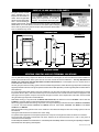
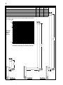
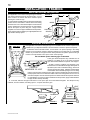
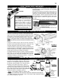
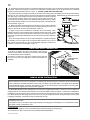
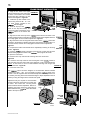
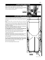
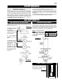
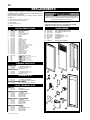
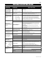
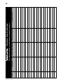
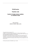
1
INSTALLER: LEAVE THIS MANUAL WITH THE APPLIANCE.
CONSUMER: RETAIN THIS MANUAL FOR FUTURE REFERENCE.
INSTALLATION AND
OPERATION INSTRUCTIONS
CERTIFIED UNDER CANADIAN AND AMERICAN NATIONAL STANDARDS: CSA 2.22, ANSI Z21.50 FOR VENTED GAS FIREPLACE.
GT8N
NATURAL GAS
GT8P
PROPANE
Certified for Canadian and United States using ANSI/CSA Methods.
SAFETY INFORMATION
!
WARNING
If the information in these instructions are not
followed exactly, a fire or explosion may result
causing property damage, personal injury or loss
of life.
- Do not store or use gasoline or other flammable
vapors and liquids in the vicinity of this or any other
appliance.
- WHAT TO DO IF YOU SMELL GAS:
● Do not try to light any appliance.
● Do not touch any electrical switch; do not use
any phone in your building.
● Immediately call your gas supplier from a
neighbour’s phone. Follow the gas supplier’s
instructions.
● If you cannot reach your gas supplier, call the
fire department.
- Installation and service must be performed by a
qualified installer, service agency or the supplier.
Wolf Steel Ltd., 24 Napoleon Rd., Barrie, ON L4M 4Y8 Canada • (705)721-1212 • fax(705)722-6031
www.napoleonfireplaces.com • [email protected]
$10.00
W415-0619 / B / 03.03.08
2
PG 2-5
TABLE of CONTENTS
INTRODUCTION
15-17
Warranty
General Instructions
General Information
Care of Glass and Plated Parts
Dimensions
5-10
10-15
FINISHING
Door Removal
Glass Removal
Frame/Front Installation
Accent Glass Installation
LK8 Light Installation (Optional)
VENTING
Venting Lengths and Air Terminal Locations
Vent Installations
Typical Vent Installations - Horizontal Termination
Typical Vent Installations - Vertical Termination
Minimum Air Terminal Location Clearances
Venting Application Flow Chart
INSTALLATION/FRAMING
Wall and Ceiling Protection
Vertical Installation
Using Flexible Vent Components
Horizontal Air Terminal Installation
Vertical Air Terminal Installation
Fireplace Vent Connection
Mobile Home Installation
Gas Installation
Electrical Connection
Stand-off Assembly
Nailing Tab Installation
Framing
Clearance to Combustibles
18
OPERATING INSTRUCTIONS
19
19
MAINTENANCE
ADJUSTMENTS
Gas Pressure Adjustment
Venturi Adjustment
Flame Characteristics
20
REPLACEMENTS
Replacement Parts
Flexible Vent Kits
Terminal Kits
Accessories
This appliance may be installed as an OEM installation in a manufactured home (USA
only) or mobile home and must be installed in accordance with the manufacturers
instructions and the Manufactured Home Construction and Safety Standard, Title 24
CFR, Part 3280 in the United States or in the Mobile Home Standard, CAN/CSA Z240
MH, Series in Canada.
This appliance is only for use with the type of gas indicated on the rating plate. This
appliance is not convertible for use with other gases, unless a certified kit is used.
This appliance may be installed in an aftermarket, permanently located, manufactured
home (USA only) or mobile home, where not prohibited by local codes.
This appliance is only for use with the type of gas indicated on the rating plate. This
appliance is not convertible for use with other gases, unless a certified kit is used.
!
•
•
•
•
•
•
•
•
•
•
•
•
•
•
•
•
WARNING
Do not burn wood or other materials in this fireplace.
Adults and especially children should be alerted to the hazards of high surface temperatures and should stay away to avoid burns or clothing ignition.
Supervise young children when they are in the same room as the fireplace.
Clothing or other flammable material should not be placed on or near the fireplace.
Due to high temperatures, the fireplace should be located out of traffic and away from furniture and draperies.
Ensure you have incorporated adequate safety measure to protect infants/toddlers from touching hot surfaces.
Even after the fireplace is out, the glass and/or screen will remain hot for an extended period of time.
Check with your local hearth specialty dealer for safety screens and hearth guards to protect children from hot surfaces. These screens and guards
must be fastened to the floor.
Any safety screen or guard removed for servicing must be replaced prior to operating the fireplace.
It is imperative that the control compartment and burner in the fireplace and venting system are kept clean. The fireplace and its venting system
should be inspected before use and at least annually by a qualified service person. More frequent cleaning may be required due to excessive lint
from carpeting, bedding material, etc. The fireplace area must be kept clear and free from combustible materials, gasoline and other flammable
vapours and liquids.
Under no circumstances should this fireplace be modified.
This fireplace must not be connected to a chimney flue pipe serving a separate solid fuel burning appliance.
Do not use this fireplace if any part has been under water. Immediately call a qualified service technician to inspect the fireplace and to replace any
part of the control system and any gas control which has been under water.
Do not operate the fireplace with the glass door removed, cracked or broken. Replacement of the glass should be done by a licensed or qualified
service person.
Do not strike or slam shut the fireplace glass door.
The glass door must be kept closed while the fireplace is operating to prevent exhaust fumes containing carbon monoxide, from entering into the
home. Temperatures of the exhaust escaping through this opening can also cause the surrounding combustible materials to overheat and catch fire.
Only doors / optional fronts certified with the unit are to be installed on the appliance.
W415-0619 / B / 03.03.08
NOTE: Changes, other than editorial, are denoted by a line in the margin.
3
®
®
®
®
The following materials and workmanship in your new NAPOLEON® gas fireplace are warranted against defects
for as long as you own the fireplace. This covers: combustion chamber, heat exchanger, stainless steel burner, gold
plated parts against tarnishing, porcelainized enameled components and aluminum extrusion trims.
Electrical (110V and millivolt) components and wearable parts such as blowers, gas valves, thermal switch,
switches, wiring, remote controls, ignitor, gasketing, and pilot assembly are covered and NAPOLEON® will
provide replacement parts free of charge during the first year of the limited warranty.
Labour related to warranty repair is covered free of charge during the first year. Repair work, however, requires
the prior approval of an authorized company official. Labour costs to the account of NAPOLEON® are based on a
predetermined rate schedule and any repair work must be done through an authorized NAPOLEON® dealer.
®
®
®
®
®
®
®
®
®
®
®
®
®
W415-0619 / B / 03.03.08
4
GENERAL INSTRUCTIONS
THIS GAS FIREPLACE SHOULD BE INSTALLED AND SERVICED BY A QUALIFIED INSTALLER to conform with local
codes. Installation practices vary from region to region and it is important to know the specifics that apply to your area, for
example: in Massachusetts State:
•
•
•
•
•
•
The fireplace damper must be removed or welded in the open position prior to installation of a fireplace insert or gas log.
A carbon monoxide detector is required in all rooms containing gas fired appliances.
The appliance off valve must be a “T” handle gas cock.
The flexible connector must not be longer than 36 inches.
The appliance is not approved for installation in a bedroom or bathroom unless the unit is a direct vent sealed combustion product.
WARNING: This product must be installed by a licensed plumber or gas fitter when installed in the Commonwealth of Massachusetts.
In absence of local codes, install to the current CAN/CGA -B149 Installation Code in Canada or to the National Fuel Gas
Code, ANSI Z223.1, and NFPA 54 in the United States. Suitable for mobile home installation if installed in accordance with
the current standard CAN/CSA Z240MH Series, for gas equipped mobile homes, in Canada or ANSI Z223.1 and NFPA 54
in the United States.
The fireplace and its individual shutoff valve must be disconnected from
the gas supply piping system during any pressure testing of that system
at test pressures in excess of 1/2 psig (3.5 kPa). The fireplace must
be isolated from the gas supply piping system by closing its individual
manual shutoff valve during any pressure testing of the gas supply piping
system at test pressures equal to or less than 1/2 psig (3.5 kPa).
When the fireplace is installed directly on carpeting, vinyl tile or other
combustible material other than wood flooring, the fireplace shall be
installed on a metal or wood panel extending the full width and depth.
GENERAL INFORMATION
FOR YOUR SATISFACTION, THIS FIREPLACE HAS BEEN TEST-FIRED TO ASSURE ITS OPERATION AND QUALITY!
RATES AND EFFICIENCIES
NATURAL GAS
PROPANE GAS
0 - 4,500*
0 - 4,500*
Maximum Input
6,000
6,000
Maximum Output
4,680
4,680
Efficiency
78%
78%
4.5” Water Column
11” Water Column
Altitude
Minimum Inlet Gas Suppy Pressure
Maximum Inlet Gas Supply Pressure
Manifold Pressure Under Flow Conditions
7” Water Column
13” Water Column
3.5” Water Column
10” Water Column
* When the fireplace is installed at elevations above 4,500ft, and in the absence of specific recommendations from
the local authority having jurisdiction, the certified high altitude input rating shall be reduced at the rate of 4% for
each additional 1,000ft.
This fireplace is approved for bathroom, bedroom and bed-sitting room installations and is suitable for mobile home
installation.
The natural gas model can only be installed in a mobile home that is permanently positioned on its site and fueled with
natural gas.
This fireplace may be installed in an aftermarket permanently located, manufactured (mobile) home, where not
prohibited by local codes.
This fireplace is only for use with the type of gas indicated on the rating plate. This fireplace is not convertible for
use with other gases, unless a certified kit is used.
Expansion / contraction noises during heating up and cooling down cycles are normal and are to be expected.
Purge all gas lines with the glass door of the fireplace open. Assure that a continuous gas flow is at the burner
before closing the door.
Objects placed in front of the fireplace must be kept a minimum of 48” from the front face of the unit.
Use only Napoleon® accessories designed for and listed with the model.
W415-0619 / B / 03.03.08
5
CARE OF GLASS AND PLATED PARTS
The glass is 3/16” ceramic
!
glass, available from your
Napoleon® / Wolf Steel Ltd. Do not substitute materials. Use care when
dealer. Clean the glass after handling glass components do not stike, or
the first 10 hours of operation
slam shut. Do not operate with broken glass.
with a recommended gas
fireplace glass cleaner. Thereafter clean as required. DO NOT CLEAN GLASS
WHEN HOT! Do not use abrasive cleaners to clean plated parts. Buff lightly
with a clean dry cloth. If the glass is not kept clean permanent discolouration
and / or blemishes may result.
WARNING
DIMENSIONS
FIGURES 1a-c
/
1 4
37 /4
43 /
3
3 4
3" DIA.
5" DIA.
ELECTRICAL
ACCESS
GAS LINE
ACCESS
2
VENTING
VENTING LENGTHS AND AIR TERMINAL LOCATIONS
The vent connection to the fireplace can be viewed by removing the baffle from the top, inside of the firebox.
Use only Wolf Steel venting components. Minimum and maximum vent lengths, for both horizontal and vertical installations,
and air terminal locations for either system are set out in this manual and must be adhered to. Use only Wolf Steel Ltd.
flexible vent components with the Wolf Steel Ltd. GD179 termination kit. This fireplace uses a 3” exhaust and a 5”
instake diameter coaxil vent system.
All outer pipe joints of these venting systems must be sealed using Red RTV and/or Mill Pac high temperature sealant (not
supplied) hereafter referred to as high temperature sealant W573-0002 (Red RTV) and the high temperature sealant W5730007 (Mill Pac).
For vent systems that provide seals on the inner exhaust flue, only the outer air intake joints must be sealed using a red high
temperature silicone (RTV). This same sealant may be used on both the inner exhaust and outer intake vent pipe joints of all
other approved vent systems except for the exhaust vent pipe connection to the fireplace flue collar which must be sealed
using the black high temperature sealant Mill Pac.
With flexible venting, in conjunction with the GD178 wall terminal kit, use either the 5 foot vent kit GDT5 or the 10 foot vent
kit GDT10. These kits allow for extended horizontal venting of the fireplace.
When using approved Wolf Steel venting components, use only the following termination kits: WALL TERMINAL KIT GD178,
or 1/12 TO 7/12 PITCH ROOF TERMINAL KIT GDT110, 8/12 TO 12/12 ROOF TERMINAL KIT GDT111, FLAT ROOF
TERMINAL KIT GDT112.
Rigid and flexible venting systems must not be combined. Wolf Steel and Simpson Dura-Vent venting systems must not
be combined.
Venting terminals shall not be recessed into a wall or siding.
For optimum flame appearance and fireplace performance, keep the vent length and number of elbows to a minimum.
The air terminal must remain unobstructed at all times. Examine the air terminal at least once a year to verify that it is
unobstructed and undamaged.
Provide adequate ventilation and combustion air. Provide adequate accessibility clearance for servicing and operating the fireplace.
Never obstruct the front opening of the fireplace.
W415-0619 / B / 03.03.08
6
VENT INSTALLATIONS
For safe and proper operation of the fireplace follow the venting instruction exactly.
Deviation from the minimum or the maximum vertical vent length can create difficulty in burner start-up and/or carboning.
Under extreme vent configurations, allow several minutes (5-15) for the flame to stabilize after ignition.
Vent lengths that pass through unheated spaces (attics, garages, crawl spaces) should be insulated with the insulation
wrapped in a protective sleeve to minimize condensation.
Provide a means for visually checking the vent connection to the fireplace after the fireplace is installed.
Use firestop spacer (W500-0358) when penetrating interior walls and ceilings.
HORIZONTAL VENT SECTIONS
A minimum clearance of 1" at the bottom, sides and top of the vent pipe in all horizontal runs to combustibles is
required. Use firestop spacer W500-0358 (supplied).
VERTICAL VENT SECTIONS
A minimum of 1" all around the vent pipe on all vertical runs to combustibles is required. Use firestop spacer
W500-0358 (not supplied).
W415-0619 / B / 03.03.08
7
TYPICAL VENT INSTALLATIONS - HORIZONTAL TERMINATION
MIN
MAX
FIGURE
Allowable 3” vent connections (excluding fireplace and air terminal connections)
N/A
1
Rise per foot (recommended)
1/4”
N/A
Rise per foot (allowable)
0”
N/A
Horizontal run (If vent run does not include vertical rise)
4”
24”
2a
Horizontal run (if vent run includes vertical rise)
4”
7 FT
2b
18”*
7 FT
2b, 2c
Vertical run
(* Immediately off the fireplace, if 7 FT maximum horizontal run is required)
See graph to determine the required vertical rise VT for the required
horizontal rise HT.
10
9
8
7
6
REQUIRED
VERTICAL
RISE IN
FEET (VT)
5
4
3
2
1.5
1
0
8”
1
2
3
4
5
6
7
8
9
10
HORIZONTAL VENT RUN PLUS OFFSET IN FEET (HT)
9 FT
MAX.
FIGURE 2a
4” MIN.
24” MAX.
7 FT MAX.
MAXIMUM
HORIZONTAL
18”
MAXIMUM
VERITICAL
4”
MIN.
4”
MIN.
8”
FIGURE 2b
FIGURE 2c
W415-0619 / B / 03.03.08
8
TYPICAL VENT INSTALLATIONS - VERTICAL TERMINATION
MIN
MAX
Allowable 3” vent connections (excluding fireplace and air terminal connections)
N/A
2
Rise per foot (recommended)
1/4”
N/A
FIGURE
Rise per foot (allowable)
0”
N/A
Vertical run (when not venting horizontally)
24”
19 1/2 FT
3a, 3c
Horizontal run
4”
5 FT
3a, 3b, 3c
See graph to determine the required vertical rise VT for the required
horizontal rise HT.
20
19.5
18
16
15
14
12
REQUIRED
VERTICAL
RISE IN
FEET (VT)
10
24”
MIN.
8
6
1.33
19 1/2 FT
MAX.
MINIMUM
4” VERITICAL
MIN.
4
2
0
1
2
3
4
5
6
7
8
9
10
HORIZONTAL VENT RUN PLUS OFFSET IN FEET (HT)
15 FT
MAX.
24”
MIN.
MINIMUM
4” VERITICAL
MIN.
FIGURE 3a
W415-0619 / B / 03.03.08
5 FT MAX.
FIGURE 3b
MAXIMUM
HORIZONTAL
FIGURE 3c
4”
MIN.
MAXIMUM
VERTICAL
9
MINIMUM AIR TERNMINAL LOCATION CLEARANCES
FIGURE 4
DE
N
C
F
A
H
H
O
M
B
B
J
K
O
G
L
O
W415-0619 / B / 03.03.08
10
INSTALLATION / FRAMING
WALL AND CEILING PROTECTION
This application occurs when venting through an exterior
wall. Having determined the air terminal location, cut and
frame a hole in an exterior wall with a minimum square
opening of 8” wide x 8” high.
1. Apply a bead of caulking all around and place the firestop
spacer over the framework to restrict cold air from being
drawn into the room or around the fireplace. Ensure that the
spacer maintains the required clearance to combustibles.
Secure the spacer in place using the 4 longer screws
supplied. Once the vent pipe is installed in its final position,
apply high temperature sealant (not supplied) between the
pipe and the firestop spacer.
FIGURE 5
INSIDE
FIRESTOP
SPACER
HIGH
RE
TEMPERATU
SEALANT
8”
G
IN
LK
U
CA
8”
OUTSIDE
VERTICAL INSTALLATION
FIGURE 6
SHIELDthrough a roof. Installation kits for various roof pitches are
This application occurs when venting
available from your Napoleon® dealer. See Accessories to order the specific kit required.
1. Determine the air terminal location, cut and frame a 8” square opening in the ceiling
and the roof to provide the minimum clearance between the vent pipe and any combustible
material. Try to center the vent pipe location midway between two joists to prevent having to
cut them. Use a plumb bob to line up the center of the openings.
Do not fill this space with any type of material.
A vent pipe shield will prevent any materials such as
insulation, from filling up the 1" air space around the
8”
pipe. Nail headers between the joist for extra support.
8”
2. Apply a bead of caulking (not supplied) to the
framework or to the Wolf Steel vent pipe shield plate or
FIRESTOP
equivalent (in the case of a finished ceiling), and secure
over the opening in the ceiling. A firestop must be placed
UNDERSIDE OF JOIST
on the bottom of each framed opening in a roof or ceiling
that the venting system passes through. Apply a bead of caulking all around and place a
firestop spacer over the vent shield to restrict cold air from being drawn into the room or
around the fireplace. Ensure that both spacer and shield maintain the required clearance
to combustibles. Once the vent pipe is installed in its final position, apply sealant between
the pipe and the firestop assembly.
3. In the attic, slide the vent pipe collar down to cover up the open end of the shield and tighten. This will prevent any
materials, such as insulation, from filling up the 1" air space around the pipe.
VENT
PIPE
COLLAR
CAULKING
VENT PIPE
SHIELD
FIGURE 7
W415-0619 / B / 03.03.08
VENT PIPE
SHIELD
FIGURE 8
11
USING FLEXIBLE VENT COMPONENTS
FIGURE 9
ELBOW
USE ONLY WOLF STEEL LTD. 3” / 5” FLEXIBLE VENT COMPONENTS.
For safe and proper operation of the fireplace, follow the venting
instructions exactly.
All 3" flexible vent pipe and 5" flexible vent pipe joints may
SPACERS
be sealed using high temperature sealant W573-0002 (not
supplied) or the high temperature sealant W573-0007 Mill
Pac (not supplied). However, the high temperature sealant
W573-0007 Mill Pac (not supplied) must be used on the
!
joint connecting the 3" flexible vent pipe and the exhaust
flue collar.
Do not allow the 3" flexible vent pipe to bunch
up on horizontal or vertical runs and elbows.
Use only approved flexible vent pipe kits marked:
WARNING
Keep it pulled tight. A 1” air gap between the
3" and 5" flexible vent pipes all around is
required for safe operation. A spacer is
required at the start, middle and end of each
elbow to ensure this gap is maintained.
Spacers are attached to the 3" flexible vent
pipe at predetermined intervals to maintain a
1” air gap to the 5" flexible vent pipe. These
spacers must not be removed.
“Wolf Steel Approved Venting” as
identified by the stamp only on the
5” flexible vent pipe.
Four inches (4”) is the minimum bend radius allowed for the
5” flexible vent pipe.
HORIZONTAL AIR TERMINAL INSTALLATION
1. Stretch the 3” flexible vent pipe to the required length taking into
account the additional length needed for the finished wall surface.
Apply a heavy bead of the high temperature sealant W573-0007
(not supplied). Slip the flexible vent pipe a minimum of 2” over the
inner sleeve of the air terminal and secure with 3 - #8 screws.
NOTE: If using pipe clamps to connect vent components, 3
screws must also be used to ensure the connection cannot
slip off.
2. Using the 5” flexible vent pipe, slide over the outer combustion
air sleeve of the air terminal and secure with 3 - #8 screws. Seal
using high temperature sealant W573-0002 (not supplied).
FIGURE 10
3. Insert the flexible vent pipe through the firestop maintaining the
required clearance to combustibles. Secure the terminal to the
exterior wall (lettering in an upright, readable position) and make
weather tight by sealing with caulking (not supplied).
4. If additional flexible vent pipe is required, couple them together
as illustrated. The vent system must be supported approximately
every 3 feet for both vertical and horizontal runs. Use noncombustible strapping to maintain the minimum 1” clearance to
combustibles from the flexible vent pipe.
FIGURE 11
VERTICAL AIR TERMINAL INSTALLATION
1. Fasten the roof support to the roof using the screws
FIGURE 12
INNER
provided. The roof support is optional. In this case the
PIPE
venting is to be adequately supported using either
an alternate method suitable to the authority having
jurisdiction or the optional roof support. Figure 12.
FIGURE 13
2. Stretch the 3" flex vent pipe to the required length.
AIR
TERMINAL
Slip the 3" flex vent pipe a minimum of 2” over the inner
CONNECTOR
pipe of the air terminal connector and secure with 3 #8
screws. Seal using a heavy bead of high temperature
HIGH
sealant W573-0007 (not supplied). Figure 13.
ROOF SUPPORT
TEMPERATURE
SEALANT
NOTE: If using pipe clamps to connect vent
components, 3 screws must also be used to ensure the connection cannot slip off.
3” FLEXIBLE
VENT PIPE
3. Repeat using the 5" flex vent pipe, using a heavy bead of high temperature sealant
5” FLEXIBLE
W573-0002 (not supplied). Figure 13.
VENT PIPE
W415-0619 / B / 03.03.08
12
4. Thread the air terminal connector / vent pipe assembly down through the roof. The air terminal must be located vertically
and plumb. Attach the air terminal connector to the roof support, ensuring that the top of the air terminal is 16” above the
highest point that it penetrates the roof. Figure 12. DO NOT CLAMP THE FLEX VENT PIPE.
5. Remove nails from the shingles, above and to the sides of the chimney. Place the flashing over the air terminal connector
leaving a min. 3/4” of the air terminal connector showing above the top of the flashing. Slide the flashing underneath the sides
and upper edge of the shingles. Ensure that the air terminal connector is properly
centred within the flashing, giving a 3/4” margin all around. Fasten to the roof. Do
FIGURE 14
not nail through the lower portion of the flashing. Make weather-tight by sealing
with caulking. Where possible, cover the sides and top edges of the flashing with
roofing material. Figure 14.
2”
AIR INLET
6. Aligning the seams of the terminal and air terminal connector, place the terminal
BASE
over the air terminal connector making sure the vent pipe goes into the hole in the
terminal. Secure with the three screws provided. Figure 14.
CAULKING
7. Apply a heavy bead of weatherproof caulking 2" above the flashing. Note:
Maintain a minimum 2” space between the air inlet base and the storm collar. Install
STORM
COLLAR
the storm collar around the air terminal and slide down to the caulking. Tighten to
ensure that a weather-tight seal between the air terminal and the collar is achieved.
WEATHER
SEALANT
Figure 14.
8. If more vent pipe needs to be used to reach the fireplace, couple them together
as illustrated. The vent system must be supported approximately every 3 feet for
FLASHING
both vertical and horizontal runs. Use noncombustible strapping to maintain the
minimum 1" clearance to combustibles. Figure 11.
FIREPLACE VENT CONNECTION
FIGURE 15
1. Install the 3” flexible vent pipe to the fireplace. Secure with 3
screws and flat washers. Seal the joint and screw holes using Mill
Pac sealant (W573-0007 not supplied).
2. Install the 5” flexible vent pipe to the fireplace. Attach and seal
the joints using the high temperature sealant W573-0002 (not
supplied).
1 1/2”
OVERLAP
HIGH
TEMPERATURE
SEALANT
SCREWS
MOBILE HOME INSTALLATION
This appliance is certified to be installed as an OEM (Original Equipment Manufacturer) installation in a manufactured
home or mobile home and must be installed in accordance with the manufacturer’s instructions and the Manufactured
Home Construction and Safety Standard, Title 24 CFR, Part 3280, in the United States or the Mobile Home Standard,
CAN/CSA Z240 MH Series, in Canada. This appliance is only for use with the type(s) of gas indicated on the rating plate.
A conversion kit is supplied with the mobile home appliance.
This Mobile/Manufactured Home Listed appliance comes factory equipped with a means to secure the unit. The fireplace is
equipped with two 1/4" diameter holes located in the front left and right corners of the base. For mobile home installations,
the fireplace must be fastened in place. Use #10 hex head screws, inserted through the holes in the base to secure. Always
turn off the pilot and the fuel supply at the source, prior to moving the mobile home. After moving the mobile home and prior
to lighting the fireplace, ensure that the logs are positioned correctly.
This appliance is certified to be installed in an aftermarket permanently located, manufactured (mobile) home, where not
prohibited by local codes.
This fireplace is only for use with the type of gas indicated on the rating plate. This fireplace is not convertible for use with
other gases, unless a certified kit is used.
Conversion Kits
The mobile home appliance is field convertible between Natural Gas (NG) and Propane (LP).
To convert from one gas to another consult your Napoleon® dealer/distributor.
W415-0619 / B / 03.03.08
13
GAS INSTALLATION
Proceed once the vent installation is complete.
Note: All gas connections must be contained within the fireplace when
complete.
FIGURE 16
1. The fireplace is designed to accept a 1/2” gas supply line. The fireplace is
equipped with a 1/2” manual shut-off valve.
2. The access to the gas inlet is located on the bottom of the outer shell.
3. The shut off must always be within the outer shell.
4. When flexing any gas line, support the gas valve so that the lines are not
kinked.
5. Check for gas leaks by brushing on a soap and water solution.
Do not use open flame.
FIGURE 17
ELECTRICAL CONNECTION
!
Do NOT use the fireplace if any part has been
under water. Call a qualified service technician
IMMEDIATELY to have the fireplace inspected for
damage to the electrical circuit.
WARNING
RISK OF ELECTRIC SHOCK!
Control and valve operate with 110v.
HARD WIRING CONNECTION
IT IS NECESSARY TO HARD WIRE THIS
FIREPLACE.
Permanently framing the fireplace with an enclosure,
requires the fireplace junction box to be hard
wired.
This fireplace must be electrically connected and
grounded in accordance with local codes. In the
absence of local codes, use the current CSA C22.1
CANADIAN ELECTRICAL CODE in Canada or
the ANSI/NFPA 70-1996 NATIONAL ELECTRICAL
CODE in the United States.
IGNITOR
IGNITOR
WIRE
OW
1 2
LL
YE
3 4
BROWN
CONTROL MODULE
PU
RP
LE
FIGURE 18
GAS
VALVE
W
H
I
T
E
B
L
A
C
K
SWITCH
GROUND
GROUND
110v
POWER
SUPPLY
JUNCTION BOX
(c/w 2 receptacles)
STAND-OFF ASSEMBLY
1
FIGURE 19a&b
2
W415-0619 / B / 03.03.08
14
NAILING TAB INSTALLATION
Attach the 4 nailing tabs supplied to the sides of the outer shell as illustrated using
the 8 self-tapping screws included in the manual baggie.
FIGURE 20
FRAMING
The
has been designed to be installed mid-way up a wall. When installing this unit close to the finished floor, the
unit must be raised a minimum of 2” (unobstructed) to allow for full rotation of the control door. It is not necessary to install
a hearth extension.
Although the unit fits between studs, most jurisdictions will not allow a “hole” in the warm air envelope of a residential structure.
It is recommended to build either an interior or exterior chase with a minimum depth of 7”.
It is best to frame your fireplace after it is positioned and the vent system is installed. Frame to local building codes.
To install the fireplace face flush with the finished surface, position the framework to accommodate the thickness of the
finished surface. Use 4 flat-head screws to secure the nailing tabs to the framing. Cover the nailing tabs with your finishing
material.
NOTE: In order to avoid the possibility of exposed insulation or vapour barrier coming in contact with the fireplace
body, it is recommended that the walls of the fireplace enclosure be “finished” (ie: drywall/sheetrock), as you would
finish any other outside wall of a home. This will ensure that clearance to combustibles is maintained within the
cavity.
FIGURES 21a,b&c
2 1/2"
2 1/2"
14 1
30 /2"
"
21 1/4"
FIGURES 22a,b&c
44 1/4"
INTERIOR BUILD-OUT
OUTSIDE
CHASE
34 7/8"
7"
14 1/2"
TM
TORCH
TM
TORCH
EXTERIOR CHASE
11 5/8"
INSIDE
CHASE
7" MIN.
2"
14 /2"
1
4"
SIDE
WALL
2"
PROTRUSION
4"
6"
W415-0619 / B / 03.03.08
7"
14 1/2"
1
2
3
FRAMING
OPENING DIMENSIONS
INSTALLATION
FINISHING
OPENING DIMENSIONS
NOTE: Finished opening is smaller than the framed opening.
15
CLEARANCES TO COMBUSTIBLES
Minimum clearance to combustible construction from fireplace and vent surfaces:
Fireplace framing: - 6” to top
- 0” to stand-offs
Vent pipe:
Recessed depth:
NON-COMBUSTIBLE
COMBUSTIBLE
(rear and sides)
- 1”
- 7”
BRICK
12”
MIN. TO
COMBUSTIBLES
(to ceiling or mantle)
6”
MIN.
1”
FRAME
0” IF
NON-COMBUSTIBLE
FINISHING IS USED
SUCH AS BRICK AN
STONE.
1”
* Any protruding finishing
material installed in this
space (ie. baseboards)
must leave 2” of
unobstructed clearance to
allow for full rotation of the
control door.
1 1/2” MIN.
CONTROL DOOR
(OPEN POSITION)
2” MIN.*
WITHOUT
FIGURE 23
FRAME INSTALLED
WITH
FRAME INSTALLED
FINISHING
DOOR REMOVAL
Before the glass door can be removed, the optional frame/
front must be removed.
The glass door is secured to the top front edge of the firebox.
Pull the handles of the latches forward, then lift the hooks out
from the slots in the door frame to release the top of the door.
Then, pivot forward until the top edge of the door clears the
front of the fireplace. Next gripping the sides of the door lift
the door out from the retainer along the bottom of the door.
CLOSED
FIGURE 24
OPEN
GLASS REMOVAL
Having removed the door, lay on a smooth flat surface, face
down. There are 4 glass retainers that need to be bent away
from the glass to release it from the frame. Do not pry on
the glass.
When replacing DO NOT SUBSTITUTE MATERIAL, replace
the gasket (W562-0008) and the glass (W300-0088). Set
new glass into the frame and gently bend tabs into the
gasket to secure.
NOTE: Care must be taken when removing and disposing
of any broken glass or damaged components. Be sure to
vacuum up any broken glass from inside the fireplace before
operation.
FIGURE 25
GLASS
GASKET
GLASS
RETAINERS
W415-0619 / B / 03.03.08
16
FRAME/FRONT INSTALLATION
1. Align the two holes in the upper
portion of the hinge on the control door FIGURE 26
to those in the bottom trim bracket,
secure using two of the #8 x 1/2” hex
head screws supplied. Figure 26
2. Install the top trim bracket to the
firebox using the three #9 - 14 x 1/2”
FIGURE 27
hex head screws supplied in the
manual baggie.
BOTTOM
3. Rest the top lip of the
TRIM
frame on the top trim bracket, and
BRACKET
the securing tabs at the bottom of the CONTROL DOOR
frame on the bottom trim
bracket.
4. Align the two slots in the top of the
frame with the two holes in the
top trim bracket and secure using the two #10 pan head screws supplied however
FRAME
do not fully tighten to leave room for adjustment. Figure 27
5. Align the holes in the securing tabs at the bottom of the
frame with
the holes in the bottom trim bracket and secure using the two remaining #8 x 1/2”
hex head screws, however do not fully tighten to leave room for adjustment.
Figure 27
TOP
TRIM
6. If required, the bottom trim bracket can be adjusted by loosening it’s securing
BRACKET
screws. Figure 27
7. Once the
frame is perfectly square and the control door will close
without rubbing against the sides of the
frame, tighten all screws.
8. Open the control door.
9. Insert the door stop chain into the receiving slot in the control door.
Figure 29
10. Insert the door stop chain into the receiving slot in the
frame so
that when fully open the control door has a clearance of 1/8” to the finished wall.
NOTE: In most cases, a count of 9 balls between receiving slots will give the
desired clearance. Figure 29
FIGURE 28
11. Close the control door.
The
frame has been designed to accommodate finished material
thicknesses of .500” - .750”. If it is necessary to pull the
frame out to
the max. .750” the magnetic catch will need to be adjusted. Minor adjustment can
be made by removing shims from behind the magnet. Major adjustments can be
made by moving the magnet to the outside of the panel.
Adjustment may be required to accommodate
the door stop chain slack when the control door
is closed. The control door securing screws
can be loosened to allow adjustment. Before retightening the screws ensure the control door is
still recessed into the
frame at a similar
offset to the top trim piece.
DOOR STOP
CHAIN
BOTTOM
TRIM
BRACKET
FIGURE 29
W415-0619 / B / 03.03.08
RECEIVING
SLOTS
17
ACCENT GLASS INSTALLATION
Carefully sprinkle the accent glass onto the glass support
evenly. Ensure no glass falls into the burner area. If this
happens, insert a clean bag into your vacuum cleaner and BURNER
vacuum out the accent glass. Replacement accent glass
can be purchased from Wolf Steel Ltd.
ACCENT
GLASS
FIGURE 30
GLASS
SUPPORT
BR
TL
BL
1. Turn off the electrical and gas supply to the fireplace.
2. Remove the frame from the unit by removing the 2 black securing
screws from the top, and the 2 silver hex head securing screws from
the bottom.
3. Lay the frame down on its front, being careful not to scratch the
finish.
4. Starting at the top of the frame, take one light assembly and carefully
snap it into place in the hole provided. Repeat for each of the light
assemblies. The wires on the top 2 light assemblies will need to be fed
in behind the heat shields.
Note: When installing the light kit be careful not to scratch your
fingers on any of the exposed screws in the frame.
5. Using Figure 31 as a guide, connect the light assemblies to the
appropriate flags on the wire harness. The wire harness is labeled (TR)
top right, (BR) bottom right (TL) Top left and (BL) bottom left.
6. Secure the wires into the clips at both sides and the bottom of the
frame. Use the extra clips provided to retain any loose wires.
7. Re-attach frame onto unit.
8. Remove the control panel by removing the 2 screws securing it along
the top edge. Leave the wires connected to the ON/OFF switch.
9. Place the transformer into the bottom of the unit. Plug the transformer
into the receptacle.
10. Lay the control panel flat along the bottom edge of the frame. Attach
one of the wire leads from the transformer to the lead on the wire harness
labeled “TRANS”, and the other to the ON/OFF switch. Attach the last
lead on the wire harness labeled “SWI” to the ON/OFF switch.
11. Re-secure the control panel.
12. Turn on the gas supply and electrical power.
TR
LK8 LIGHT INSTALLATION (OPTIONAL)
CLIPS X5
A
TR
I
SW
NS
FIGURE 31
W415-0619 / B / 03.03.08
18
OPERATING INSTRUCTIONS
When lit for the first time, the fireplace will emit a slight odour for
a few hours. This is a normal temporary condition caused by the
curing of paints and lubricants used in the manufacturing process
and will not occur again. Simply open a window to sufficiently
ventilate the room.
After extended periods of non-operation such as following a
vacation or a warm weather season, the fireplace may emit a
slight odour for a few hours. This is caused by dust particles in
the heat exchanger burning off. Open a window to sufficiently
ventilate the room.
Purge all gas lines with the glass door of the fireplace open.
Assure that a continuous gas flow is at the burner before
closing the door.
WHAT TO DO IF YOU SMELL GAS:
FOR YOUR SAFETY READ BEFORE LIGHTING:
A. This fireplace is equipped with an ignition device which
automatically lights the burner. Do not try to light by hand.
B. Before operating, smell all around the fireplace area for
gas and next to the floor because some gas is heavier than
air and will settle on the floor.
C. Do not use this fireplace if any part has been under water.
Immediately call a qualified service technician to inspect the
fireplace and replace any part of the control system and any
gas control which has been under water.
•
•
•
•
Turn off all gas to the fireplace.
Open windows.
Do not try to light any appliance.
Do not touch any electrical switch; do not use any phone in
your building.
• Immediately call your gas supplier from a neighbor’s
phone. Follow the gas supplier’s instructions.
• If you cannot reach your gas supplier, call the fire
department.
LIGHTING INSTRUCTIONS
1. STOP! Read the safety information located above.
2. Turn off all electric power to the fireplace.
3. This fireplace is equipped with an ignition device which
automatically lights the burner. Do not try to light by hand.
4. Remove the glass door.
5. Wait five (5) minutes to clear out any gas. If you smell gas
including near the floor STOP! Follow “B” in the above safety
information on this label. If you don’t smell gas go to the next
step.
6. Replace the glass door.
7. Turn on all electric power to the fireplace.
8. Turn the fireplace switch to the ON position.
9. If fireplace will not operate, follow instructions “To Turn Off
Gas” and call your service technician or gas supplier.
FIGURE 32
TO TURN OFF GAS
1. Turn the fireplace switch to the OFF position.
2. Turn off all electrical power to the fireplace if service is to
be preformed.
3. Turn manual shut-off valve clockwise to
Do not force.
off.
RATING PLATE
RATING LABEL LOCATION: The rating label is located under the control panel and is chained to the fireplace.
DO NOT REMOVE.
ERTEK
INT
CM
C
W
ar
noc
r
k He
se
y
US
REFERENCE #15901
CERTIFIED UNDER : CSA 2.22-2007, ANSI 21.50-2007 VENTED GAS FIREPLACE
DIRECT VENT GAS FIREPLACE. APPROVED FOR BEDROOM, BATHROOM AND BED SITTING ROOM INSTALLATION.
SUITABLE FOR MOBILE HOME INSTALLATION IF INSTALLED IN ACCORDANCE WITH THE CURRENT STANDARD CAN/CSA
Z240MH SERIES GAS EQUIPPED MOBILE HOMES. IN CANADA OR IN THE UNITED STATES THE MANUFACTURED HOME
CONSTRUCTION AND SAFETY STANDARD. TITLE 24 DFR, PART 3280. WHEN THIS US STANDARD IS NOT APPLICABLE USE
THE STANDARD FOR FIRE SAFETY CRITERIA FOR MANUFACTURED HOME INSTALLATIONS, SITES AND COMMUNITIES,
ANSI/NFPA 501A.
MODEL
MODEL
CERTIFIED FOR CANADA AND USA
GT8N
GT8P
(NATURAL GAS)
(PROPANE)
0-4500FT (0-1370m)
ALTITUDE
0-4500FT (0-1370m)
6,000 BTU/h
INPUT
6,000 BTU/h
#56
ORIFICE
#69
MANIFOLD PRESSURE: 3.5" WATER COLUMN MANIFOLD PRESSURE: 10" WATER COLUMN
MINIMUM SUPPLY PRESSURE: 4.5" WATER COLUMN MINIMUM SUPPLY PRESSURE: 11" WATER COLUMN
MAXIMUM SUPPLY PRESSURE: 7.0" WATER COLUMN MAXIMUM SUPPLY PRESSURE: 13" WATER COLUMN
VENTED GAS FIREPLACE NOT FOR USE WITH SOLID FUEL. FOR USE WITH GLASS
WARNING: DO NOT ADD ANY MATERIAL TO THE
DOOR. CERTIFIED WITH THIS UNIT ONLY.
APPLIANCE, WHICH WILL COME IN CONTACT WITH
THE FLAMES, OTHER THAN THAT SUPPLIED BY THE
THE APPLIANCE MUST BE VENTED USING THE APPROPRIATE NAPOLEON VENT
MANUFACTURER WITH THE APPLIANCE.
KITS, SEE OWNERS INSTALLATION MANUAL FOR VENTING SPECIFICS. PROPER
MINIMUM CLEARANCES TO COMBUSTIBLE MATERIALS
TOP
6”
RECESSED DEPTH
7”
FLOOR
0”
VENT
1”
SIDES
0”
BACK
1 1/2”
TOP, SIDES & BACK AS PER ABOVE. FOR FINISHING
MATERIAL, SEE OWNERS MANUAL.
ELECTRICAL RATING: 115v 0.82AMP, 60HZ
MINIMUM AND MAXIMUM HORIZONTAL VENT LENGTHS
ARE 10 INCHES AND 10 FEET RESPECTIVELY.
MINIMUM AND MAXIMUM VERTICAL VENT LENGTHS
ARE 36 INCHES AND 10 FEET RESPECTIVELY.
W415-0619 / B / 03.03.08
REINSTALLATION AND RESEALING IS NECESSARY AFTER SERVICING THE
VENT-AIR INTAKE SYSTEM.
THIS APPLIANCE IS ONLY FOR USE WITH THE TYPE OF GAS INDICATED ON THE
RATING PLATE AND MY BE INSTALLED IN AN AFTERMARKET, PERMANENTLY
LOCATED, MANUFACTURED HOME (USA ONLY) OR MOBILE HOME WHERE NOT
PROHIBITED BY LOCAL CODES. SEE OWNER’S MANUAL FOR DETAILS. THIS
APPLIANCE IS NOT CONVERTIBLE FOR USE WITH OTHER GASES, UNLESS A
CERTIFIED KIT IS USED.
MADE IN CANADA
WOLF STEEL LTD, BARRIE, ON, CANADA
SERIAL NUMBER:
GT8
W385-0381 / A
19
MAINTENANCE
TURN OFF THE GAS AND ELECTRICAL POWER BEFORE
SERVICING THE FIREPLACE.
CAUTION: Label all wires prior to disconnection when servicing
controls. Wiring errors can cause improper and dangerous
operation. Verify proper operation after servicing. This fireplace
and its venting system should be inspected before use and at
least annually by a qualified service person. The fireplace area
must be kept clear and free of combustible materials, gasoline
or other flammable vapours and liquids. The flow of combustion
and ventilation air must not be obstructed.
1. Keep the control compartment, burner, and air shutter opening
clean by vacuuming or brushing, at least once a year.
2. Check to see that the main burner ignites when the switch
for the burner is turned on. A 5 second light-up period is satisfactory. If ignition takes longer, consult your Napoleon® dealer
/ distributor.
3. Check that the gasketing on the sides, top and bottom of the
door is not broken or missing. Replace if necessary.
ADJUSTMENTS
GAS PRESSURE ADJUSTMENT
VENTURI ADJUSTMENT
Outlet pressure can be adjusted if not measuring 3.5” W.C.
(NG) or 10.0” W.C. (LP).
Closing the air shutter will cause a more yellow flame, but can
lead to carboning. Opening the air shutter will cause a more
blue flame, but can cause flame lifting from the burner ports.
The flame may not appear yellow immediately; allow 15 to 30
minutes for the final flame color to be established.
1. Pressure can be
checked by removing
cap (A) using
a 3/16 allen key and
replacing it with a 1/8
NPT barb fitting.
FIGURE 33
NOTE: It is important that
the venturi sits down tight
on the orifice. The burner
is adjustable up/down to
ensure this.
2.
Place pressure
gauge tube over the
fitting.
AIR SHUTTER OPENINGS
LP
5/16” DIA (x2)
NG
3/16” DIA (x1)
FIGURE 35
3. Pressure can be
adjusted by removing
cap (B) using a flat
screwdriver,
and
adjusting the nylon
plug with the same
screw driver. Turning
the plug in (clockwise)
will
increase
the
pressure.
FIGURE 34
FLAME CHARACTERISTICS
It is important to periodically
perform a visual check of the
burner flame. Compare them to
the illustration provided.
FIGURE 36
W415-0619 / B / 03.03.08
20
REPLACEMENTS
Contact your dealer for questions concerning prices and availability
of replacement parts. Normally all parts can be ordered through your
Napoleon® dealer or distributor.
When ordering replacement parts always give the following
information:
1.
2.
3.
4.
5.
MODEL & SERIAL NUMBER OF FIREPLACE
INSTALLATION DATE OF FIREPLACE
PART NUMBER
DESCRIPTION OF PART
FINISH
!
FOR WARRANTY REPLACEMENT PARTS, A PHOTOCOPY OF THE ORIGINAL
INVOICE WILL BE REQUIRED TO HONOUR THE CLAIM.
* IDENTIFIES ITEMS WHICH ARE NOT ILLUSTRATED. FOR FURTHER
INFORMATION, CONTACT YOUR NAPOLEON® DEALER.
ACCESSORIES
REPLACEMENT PARTS
#
1
2*
3*
4
5*
6
7
8
9*
10*
11
12
13
13
14*
14*
15
16
17*
18*
19
20
21*
22
22
22
22
22
PART NO. DESCRIPTION
W225-0216
W562-0008
W010-1736
W010-1743
W300-0088
W100-0104
W357-0006
W190-0026
W750-0183
W750-0184
W200-0234
W200-0233
W725-0052
W725-0053
W455-0085
W455-0086
W500-0358
W475-0522
W300-0108
W385-0334
W290-0123
W290-0125
W562-0046
TFK
TFR
TFP
TFW
TFB
DOOR FRAME
DOOR GASKET
DOOR LATCH ASSEMBLY
GLASS C/W GASKET
GLASS
BURNER
IGNITOR
CONTROL, MODULE
WIRE HARNESS
IGNITION CABLE
IGNITOR COVER
BURNER COVER
NATURAL GAS VALVE - 3.5” W.C.
PROPANE GAS VALVE - 10.0” W.C.
NATURAL GAS ORIFICE
PROPANE GAS ORIFICE
FIRESTOP SPACER
BACK PANEL
ACCENT GLASS (BLACK)
NAPOLEON® LOGO
EXHAUST GASKET
BURNER GASKET
ROPE GASKET, BACK PANEL
FRAME - PAINTED METAILIC BLACK FINISH
FRAME - RED FINISH
FRAME - PEWTER FINISH
FRAME - WHITE FINISH
FRAME - STEEL BLUE FINISH
WARNING
Failure to position the parts in accordance with these diagrams or
failure to use only parts specified approved with this appliance may
result in property damage or personal injury.
35*
35*
36*
37*
38*
39*
40*
41*
42*
W573-0002
W573-0007
W175-0204
W175-0166
W175-0270
W175-0274
W175-0271
LK8
AVS35KT
HIGH TEMPERATURE SEALANT
HIGH TEMPERATURE SEALANT
3” COUPLER
5” COUPLER
CONVERSION KIT - NG TO LP
CONVERSION KIT - LP TO NG
COUPLER KIT
LIGHT KIT
VENT SLEEVE ASSEMBLY
FLEXIBLE VENT KITS
GDT5 (5 FT)
23*
24*
25*
W730-0031
W730-0032
W615-0080
3” FLEXIBLE VENT PIPE - (5 FT)
5” FLEXIBLE VENT PIPE - (5 FT)
SPACERS (3 INCLUDED)
26*
27*
25*
W730-0033
W730-0034
W615-0080
3” FLEXIBLE VENT PIPE - (10 FT)
5” FLEXIBLE VENT PIPE - (10 FT)
SPACERS (6 INCLUDED)
GDT10 (10 FT)
16
1
4
TERMINAL KITS
GD178 (WALL TERMINAL KIT)
28*
29
W010-1744
W670-0010
12” FLEXIBLE VENT ASSEMBLY
3”/5” FLEXIBLE HORIZONTAL TERMINAL
29
W670-0010
3”/5” FLEXIBLE HORIZONTAL TERMINAL
6
7
8
GD179 (TERMINAL ONLY)
ROOF TERMINAL KITS
GDT113
30*
31*
W670-0011
W490-0076
AIR TERMINAL
3/5 INNER/OUTER SLEEVE
30*
31*
32*
33*
34*
W670-0011
W490-0076
W010-1844
W263-0099
W170-0134
AIR TERMINAL
3/5 INNER/OUTER SLEEVE
ROOF SUPPORT
ROOF FLASHING
STORM COLLAR
30*
31*
32*
33*
34*
W670-0011
W490-0076
W010-1844
W263-0100
W170-0134
AIR TERMINAL
3/5 INNER/OUTER SLEEVE
ROOF SUPPORT
ROOF FLASHING
STORM COLLAR
30*
31*
32*
33*
34*
W670-0011
W490-0076
W010-1844
W263-0101
W170-0134
AIR TERMINAL
3/5 INNER/OUTER SLEEVE
ROOF SUPPORT
ROOF FLASHING
STORM COLLAR
GDT110 (1/12 - 7/12 PITCH)
12
11
13
19
GDT111 (8/12 - 12/12 PITCH)
20
15
GDT112 (FLAT ROOF)
W415-0619 / B / 03.03.08
29
22
21
TROUBLE SHOOTING GUIDE
BEFORE ATTEMPTING TO TROUBLESHOOT, PURGE YOUR UNIT AND INITIALLY LIGHT THE IGNITOR AND THE MAIN BURNER WITH THE GLASS DOOR OPEN.
SYMPTOM
PROBLEM
Electrode sparks, burner
ignites, electrode
continues to spark for
complete 7 seconds,
burner shuts down.
Hot and neutral wires are reversed
at control module.
- Connect the hot wire to the black wire. Connect the neutral wire to
the white wire.
Sensor / flame not connecting
- Raise electrode / sensor up into flame.
Blockage in vent.
- Remove blockage. In extremely cold conditions, ice buildup may occur
on the terminal and should be removed as required.
Main burner flame is a
blue, lazy, transparent
flame.
Flame length
consistently too large
or too small. Carboning
occurs.
TEST SOLUTION
Unit is over-fired or under-fired.
- Check pressure readings
- Outlet pressure can be checked by removing cap (A) and replacing
it with a 1/8” NPT barb fitting. Next, place pressure gauge tubing
over the fitting. Gauge should read 3.5” W.C. for natural gas or
10.0” W.C. for propane. AFTER TAKING PRESSURE READINGS,
BE SURE TO REPLACE CAP TO RESEAL. DO NOT OVER-TORQUE.
- Leak test with a soap and water solution.
Air shutter has become blocked.
- Ensure air shutter opening is free of lint or other obstructions.
Flame is impinging on the
combustion chamber.
- Open air shutter to increase the primary air.
- Check the input rate: check the manifold pressure and orifice size as
specified by the rating plate values.
- Check that the door gasketing is not broken or missing and that the
seal is tight.
- Check that both 3” and 5” vent liners are free of holes and well
sealed at all joints.
- Check that the minimum rise per foot has been adhered to for any
horizontal venting.
White / grey film forms.
Sulphur from fuel is being
deposited on glass, logs or
combustion chamber surfaces.
- Clean the glass with a gas fireplace glass cleaner. DO NOT CLEAN
GLASS WHEN HOT. If deposits are not cleaned off regularly, the
glass may become permanently marked.
Exhaust fumes smelled in
room, headaches.
Fireplace is spilling.
- Check door seal.
- Check pressure relief device.
- Check for chimney blockage.
- Ensure that the paint curing process is complete.
Switch is defective.
- Connect a jumper wire across the wall switch terminals; if main
burner lights, replace switch / thermostat.
Burner orifice is blocked.
- Remove stoppage in orifice.
Control valve faulty.
- Replace.
Carbon is being
deposited on glass, logs
or combustion chamber
surfaces.
No gas to the main
burner; switch is on.
Burner will not light,
ignitor sparks.
Ignitor
will
not
spark.
Remote wall switch is in
“OFF” position; burner
comes on.
Faulty valve.
- Replace.
No gas at the burner.
- Check that the manual valve is turned on.
- Replace the valve.
Out of propane gas.
- Fill the tank.
No spark at ignitor.
- Check the power source. (ie. fuse, circuit breaker)
- Check that the wire is connected to both the ignitor and the control
module.
- Check that the spark is not jumping to ignitor cover.
- Replace the wire if the wire insulation is broken or frayed.
- Replace the electrode if the ceramic insulator is cracked or broken.
Spark gap is incorrect.
- Spark gap should be 0.125” (1/8” approx.) from the electrode tip to the
sensor tip.
Wall switch is mounted upside
down.
- Reverse.
Remote wall switch is grounding.
- Replace.
Remote wall switch wire is
grounding.
- Check for ground (short); repair ground or replace wire.
Faulty wire.
- Replace.
W415-0619 / B / 03.03.08
DATE
DEALER NAME
SERVICE TECHNICIAN NAME
SERVICE PERFORMANCE
This fireplace must be serviced annually depending on usage
Fireplace Service History
SPECIAL CONCERNS
22
W415-0619 / B / 03.03.08