1
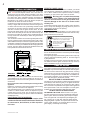
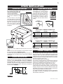
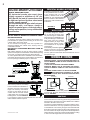
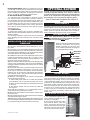
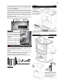
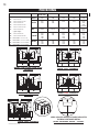
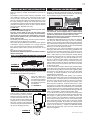
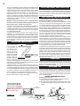
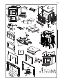
1
INSTALLER: LEAVE THIS MANUAL WITH THE APPLIANCE
CONSUMER: RETAIN THIS MANUAL FOR FUTURE REFERENCE
INSTALLATION
AND OPERATION
INSTRUCTIONS
CERTIFIED UNDER U.S. ENVIRONMENTAL PROTECTION AGENCY (E.P.A.) JULY 1990 AND THE OREGON DEPARTMENT OF ENVIRONMENTAL QUALITY (D.E.Q.) PARTICULATE
EMISSION STANDARDS BY E.E.M.C THESE STOVES HAVE BEEN TESTED AND LISTED BY INTERTEK TESTING SERVICES TO STANDARDS: CSA B366.2, ULC S627, UL 1482. MODEL
1100 HAS BEEN TESTED AND LISTED FOR INSTALLATION IN MOBILE HOMES.
EPA 1100, 1100L, 1100C, 1150,
1400, 1400L, 1450 & 1900
FREE STANDING MODELS
EPI 1101, 1402
INSERT MODEL
SAFETY INFORMATION
!
WARNING
If the information in these instructions is not followed exactly, a fire or
explosion may result causing property damage, personal injury or death.
Improper installation, adjustment, alteration, service or maintenance can
cause injury or property damage, bodily injury or even death. Please read
entire manual before you install and use your fireplace.
This fireplace has not been tested with an unvented gas log set. To reduce
risk of fire or injury, do not install an unvented gas log set into the fireplace.
- This fireplace can be very hot when burning.
- Combustible materials such as firewood, wet clothing, etc. placed too close can catch fire.
- Children and pets must be kept from touching the fireplace when it is hot.
- The chimney must be sound and free of cracks. Before installing this unit, contact the local
building or fire authority and follow their guidelines.
- Operate only with the door tightly closed.
- Burn wood behind the log retainer directly on the firebricks.
- Do not use an elevated grate or otherwise raise the fire.
- At least 14 square inches of outside air must be admitted to the room or directly to the unit
through a 4” diameter pipe.
- This fireplace is designed to burn natural wood only. Higher efficiencies and lower emissions
generally result when burning air dried seasoned hardwoods, as compared to softwoods or
to green or freshly cut hardwoods.
- Do not start a fire with chemicals or fluids such as gasoline, engine oil, etc.
- Do not burn treated wood, coal, charcoal, colored paper, cardboard, solvents or garbage.
- Do not let the fireplace become hot enough for any part to glow red.
- KEEP THE STOVE TOP TEMPERATURE BELOW 700°F (371°C). Attempts to acheieve
heat output rates that exceed design specifications can result in steel distortion and
damage.
Wolf Steel Ltd., 24 Napoleon Rd., Barrie, ON L4M 4Y8 Canada s (705)721-1212 s fax(705)722-6031
www.napoleonfireplaces.com s [email protected]
W415-0512 / D / 07.16.08
$10.00
W415-0512 / D / 07.16.08
2
PG
2-4 INTRODUCTION
5-6
6-7
7-8
8-9
TABLE of CONTENTS
10-11 FINISHING
Warranty
General Information
Care of Plated & Enamelled Parts
Care of Glass
INSTALLATION
11-13
Installing the Legs
Alcove Installation
Stove Installation
Chimney Connection
Adding Chimney Sections
Outside Air
Wall Pass-through
MOBILE HOME
13-14
Venting
Outside Air
Brick Installation
Ornamental Trivet Installation
Door and Handles Installation
Pedestal Trim Installation
Optional Ash Drawer Kit
OPERATION
Achieving Proper Draft
Fire Extinguishers and Smoke Detectors
Fuel Loading and Burn Cycle
Flash Fire
Extended Fire
Smoking
Ash Removal Procedures
MAINTENANCE
Creosote Formation and Removal
Runaway or Chimney Fire
Gasket Replacement
Door Removal
FIREPLACE INSERT
Prior to Installation
Installation into a Masonry Fireplace
Installation into a Factory Built Fireplace
OPTIONAL BLOWER
14
15-17
Stove Models
Leg Models
Insert Models
1101 Blower Service and Replacement
1402 Blower Service and Replacement
1150 Blower Installation
1150 Features
WOOD PILE MAINTENANCE
REPLACEMENTS
Ordering Replacement Parts
Replacement Parts
Accessories
PLEASE RETAIN THIS MANUAL FOR FUTURE REFERENCE
MODEL 1100,
1100C &
1100L
MODEL 1150
MODEL 1101
(INSERT)
MODEL 1400,
1400L, & 1450
MODEL 1402
(INSERT)
MODEL 1900
WIDTH
25 1/2” (65 cm)
29 3/8”. (74.6 cm)
28” (71 cm)
25 1/2” (65 cm)
25 1/2” (65 cm)
25 1/2” (65 cm)
DEPTH
22 1/2” (57 cm)
23 3/16” (58.8 cm)
27” (69 cm)
27” (69 cm)
27” (69 cm)
31 1/2” (80 cm)
Specifications
DEPTH BEHIND
FLASHING
16 1/2 to 21” (42 to
54 cm)
14 1/2” (37 cm)
FLUE CENTERLINE TO REAR
6 1/2” (16.51 cm)
6 3/4” (17.1 cm)
11” (27.94 cm)
7 1/2” (19.05 cm)
5 1/2” (13.97 cm)
7 1/2“ (19.05 cm)
FLUE CENTERLINE TO SIDE
12 3/4” (32.39 cm)
14 11/16” (37.39
cm)
14” (35.56 cm)
12 3/4” (32.39 cm)
12 3/4” (32.39 cm)
12 3/4” (32.39 cm)
HEIGHT PEDESTAL MODEL
33 1/4” (84 cm)
36 1/2” (92.7 cm)
21 1/4” (54 cm)
33 1/4” (84 cm)
21 1/4” (54 cm)
33 1/4” (84 cm)
HEIGHT CAST
MODEL
28 1/2” (72 cm)
32” (81 cm)
1.7ft3 (0.05m3)
CHAMBER
(D.W.H)
13 1/2x18x12”
(34x46x31 cm)
13 1/2x18x12”
(34x46x31 cm)
CAPACITY
1.7ft3 (0.05m3)
HEIGHT LEG
MODEL
32” (81 cm)
13 1/2x18x12”
(34x46x31 cm)
18x18x12”
(46x46x31 cm)
18x18x12”
(46x46x31 cm)
22 1/2x18x12”
(57x46x31 cm)
1.7ft3 (0.05m3)
2.25ft3 (0.06m3)
2.25ft3 (0.06m3)
3.0ft3 (0.08 m3)
APPROX. AREA
HEATED*
t2
600-1500 f
(56-139 m2)
t2
600-1500 f
(56-139 m2)
t2
t2
t2
600-1500 f
(56-139 m2)
1000-2000 f
(93-186 m2)
1000-2000 f
(93-186 m2)
1000-3500 ft2
(93-325 m2)
HEAT OUTPUT
(HIGH BURN) **
55,000 BTU
55,000 BTU
55,000 BTU
70,000 BTU
70,000 BTU
85,000 BTU
DURATION LOW
FIRE*
7 Hours
7 Hours
7 Hours
9 Hours
9 Hours
12 Hours
WEIGHT w/o
BRICKS
215 lbs (97.5 kg)
280 lbs (127 kg)
185 lbs (83.9 kg)
250 lbs (113 kg)
250 lbs (113 kg)
285 lbs (129 kg)
WEIGHT OF
BRICKS
110 lbs (54.4 kg)
110 lbs (54.4 kg)
110 lbs (54.4 kg)
145 lbs (65 kg)
145 lbs (65 kg)
114 lbs (52 kg)
*FIGURES WILL VARY CONSIDERABLY WITH INDIVIDUAL CONDITIONS.
W415-0512 / D / 07.16.08
** WOLF STEEL LTD. ESTIMATED REALISTIC BTU/H WITH HARDWOOD LOGS AND REGULAR REFUELING.
NOTE: Changes, other than editorial, are denoted by a vertical line in the margin.
3
NAPOLEON® products are manufactured under the strict Standard of the World Recognized
ISO 9001 : 2000 Quality Assurance Certificate.
NAPOLEON® products are designed with superior components and materials, assembled by trained craftsmen
who take great pride in their work. The complete fireplace is thoroughly inspected by a qualified technician before
packaging to ensure that you, the customer, receives the quality product that you expect from NAPOLEON®.
NAPOLEON® WOOD FIREPLACE PRESIDENT’S LIFETIME LIMITED WARRANTY
The following materials and workmanship in your new NAPOLEON® wood fireplace are warranted against
defects for as long as you own the fireplace. This covers: combustion chamber, heat exchanger, ceramic glass
(thermal breakage only), gold plated parts against tarnishing, porcelainized enamelled components, aluminum
extrusion trims ashdrawer, and cast iron castings.
Electrical (110V) components and wearable parts such as blowers, thermal switch, switches, wiring, firebrick,
gasketing, stainless steel baffle retainer, and high temperature paint are covered and NAPOLEON® will provide
replacement parts free of charge during the first year of the limited warranty.
Labour related to warranty repair is covered free of charge during the first year. Repair work, however, requires
the prior approval of an authorized company official. Labour costs to the account of NAPOLEON® are based on a
predetermined rate schedule and any repair work must be done through an authorized NAPOLEON® dealer.
CONDITIONS AND LIMITATIONS
NAPOLEON® warrants its products against manufacturing defects to the original purchaser only -- i.e., the individual or legal entity
(registered customer) whose name appears on the warranty registration card filed with NAPOLEON® -- provided that the purchase
was made through an authorized NAPOLEON® dealer and is subject to the following conditions and limitations:
This factory warranty is non-transferable and may not be extended whatsoever by any of our representatives.
The wood fireplace must be installed by an authorized service technician or contractor. Installation must be done in accordance with
the installation instructions included with the product and all local and national building and fire codes.
This limited warranty does not cover damages caused by misuse, lack of maintenance, accident, alterations, abuse or neglect and
parts installed from other manufacturers will nullify this warranty.
This limited warranty further does not cover any scratches, dents, corrosion or discolouring caused by excessive heat, abrasive and
chemical cleaners nor chipping on porcelain enamel parts, nor any venting components used in the installation of the fireplace.
In the first year only, this warranty extends to the repair or replacement of warranted parts which are defective in material or workmanship provided that the product has been operated in accordance with the operation instructions and under normal conditions.
After the first year, with respect to the President’s Limited Lifetime Warranty, NAPOLEON® may, at its discretion, fully discharge all
obligations with respect to this warranty by refunding to the original warranted purchaser the wholesale price of any warranted but
defective part(s).
After the first year, NAPOLEON® will not be responsible for installation, labour or any other costs or expenses related to the reinstallation of a warranted part, and such expenses are not covered by this warranty.
Notwithstanding any provisions contained in the President’s Limited Lifetime Warranty, NAPOLEON’S responsibility under this warranty is defined as above and it shall not in any event extend to any incidental, consequential or indirect damages.
This warranty defines the obligations and liability of NAPOLEON® with respect to the NAPOLEON® wood fireplace and any other
warranties expressed or implied with respect to this product, its components or accessories are excluded.
NAPOLEON® neither assumes, nor authorizes any third party to assume, on its behalf, any other liabilities with respect to the sale
of this product. NAPOLEON® will not be responsible for: over-firing, downdrafts, spillage caused by environmental conditions such
as rooftops, buildings, nearby trees, hills, mountains, inadequate vents or ventilation, excessive venting configurations, insufficient
makeup air, or negative air pressures which may or may not be caused by mechanical systems such as exhaust fans, furnaces, clothes
dryers, etc.
Any damages to fireplace, combustion chamber, heat exchanger, brass trim or other component due to water, weather damage, long
periods of dampness, condensation, damaging chemicals or cleaners will not be the responsibility of NAPOLEON®.
The bill of sale or copy will be required together with a serial number and a model number when making any warranty claims from
your authorized dealer. The warranty registration card must be returned within fourteen days to register the warranty.
NAPOLEON® reserves the right to have its representative inspect any product or part thereof prior to honouring any warranty
claim.
ALL SPECIFICATIONS AND DESIGNS ARE SUBJECT TO CHANGE WITHOUT PRIOR NOTICE DUE TO ON-GOING PRODUCT IMPROVEMENTS. NAPOLEON® IS A REGISTERED
TRADEMARK OF WOLF STEEL LTD. PATENTS U.S. 5.303.693.801 - CAN. 2.073.411, 2.082.915. © WOLF STEEL LTD.
W415-0512 / D / 07.16.08
4
GENERAL INFORMATION
Except for their different depths, models 1100, 1150, 1400,
1900, 1450 and the fireplace inserts 1101, and 1402 are
identical and use the same burning principles. They were
specifically designed over many months of research to meet
the 1990 U.S.A. EPA particulate emission standards and
have been extensively tested in Canadian and American
laboratories. This system is the most efficient, simple and
trouble free we know and works as follows:
Combustion air enters through two holes in the bottom covered by a single draft control. Air from the front hole goes up
on either side of the door into a preheating airwash located
across the top and then down the window to feed the fire
and also to ensure that the glass remains clean. Air from
this hole also feeds directly into the combustion chamber at
hearth level. Secondary air from the rear hole travels up the
back in the secondary air housing to the manifold located at
the top and shoots out laterally to oxidize the gases below
the smoke exit.
The combustion chamber is lined with high temperature firebrick on 2 sides, the back and across the bottom, with a layer
of fibre baffles at the top to maintain a high temperature in the
combustion chamber so that gases mixing with the preheated
air from the secondary air manifold tube are easily ignited and
burned. The stove sides and back are shielded to direct the
heat upwards and forwards into the room.
FLUE GLASS
DÉFLECTEUR EN FIBRE
HOT SECONDARY AIR
FIBRE BRICKS
RÉFRACTAIRES
2 SIDES,
BACK
& BOTTOM
CERAMIC
GLASS
DRAFT CONTROL
CLOSED
OPEN
PRIMARY AIR
FIGURE 1
COMBUSTION AIR
INTAKE
SECONDARY AIR
Be sure to provide sufficient combustion air. There are many
other appliances in your home competing for air such as: a
kitchen range hood, forced air heating devices or a bathroom
exhaust fan.
Do not connect this unit to a chimney flue serving another
appliance.
Expansion / contraction noises during heating up and cooling
down cycles are normal and to be expected.
After extended periods of non-operation such as following a
vacation or a warm weather season, the fireplace may emit
a slight odour for a few hours. This is caused by dust particles on the firebox burning off. Open a window to sufficiently
ventilate the room.
CALIFORNIA PROP 65 WARNING:
Use of this product may produce smoke which
contains chemicals known to the State of California
to cause cancer, birth defects, or other reproductive harm.
W415-0512 / D / 07.16.08
PEDESTAL MODELS ONLY
If the outside air feature of the stove is utilized, you should
never experience a shortage of combustion air. If you choose
not to utilize outside air and experience draft or smoking
problems, you may need to open a door or window.
WARNING: Burning your unit with the ash dump
door open or ajar creates a fire hazard that may
result in discoloration to the gold plated door,
internal damage to the stove or a house and/or
chimney fire.
To ensure that the ash dump door is tightly closed, allow the
door to snap shut dislodging anything (ashes or pieces of
coal) that may be stuck in the opening.
LEG MODELS ONLY
If you experience smoking problems, you may need to open
a door, a window or otherwise provide some method of supplying combustion air to the unit.
We suggest that our woodburning hearth products
be installed and serviced by professionals who are
certified in the U.S. by the National Fireplace
Institue® (NFI) as NFI Woodburning Specialists or
who are certified in Canada by
Wood Energy Technical
Training (WETT).
CARE OF ALL PLATED AND ENAMELED PARTS
Do not use abrasive cleaners to clean these parts. Buff lightly
with a clean dry cloth.
Prolonged high temperature burning with the door ajar may
cause a permanent rainbowing effect on the lower edge of
a gold plated door.
Porcelain enamel components must be handled with care.
The baked-on finish is “glass”. If struck, it will chip. Touch-up
paint is available through your Napoleon dealer.
CARE OF GLASS
If the glass is not kept clean permanent discolouration and / or
blemishes may result. Normally a hot fire will clean the glass.
The most common reasons for dirty glass include; not using
sufficient fuel to get the stove thoroughly hot, using green or
wet wood, closing the draft so far that there is insufficient air
for complete combustion. If it is necessary to clean the glass,
use a soft cloth with a nonabrasive cleaner.
DO NOT CLEAN GLASS WHEN HOT!
The glass is very strong but do not let burning fuel rest against
it and always close the door gently. If the glass should ever
crack while the fire is burning, do not open the door until the
fire is out and do not operate the stove again until the glass has
been replaced with a new 5mm thick plate of ceramic glass,
available from your Napoleon / Wolf Steel Ltd. dealer.
DO NOT SUBSTITUTE MATERIALS.
TO REMOVE THE GLASS: When the unit is cool, open
the door and remove the screws and brackets holding the
glass in place. Remove all broken glass. Wrap the edges
of the new glass with a U-shaped strip of fiberglass gasket, covering 1/4” on each side. Place the glass with the
fiberglass gasket in position and replace the brackets and
screws. When finished, you should be able to move the
glass slightly, horizontally and vertically.
5
STOVE INSTALLATION
STOVE INSTALLATION
8"
8"
8"
18"
FIGURE 4A
BACK WALL
BACK WALL
B
A
SIDE WALL
To avoid being damaged during shipping, the stove has
been bolted to the pallet and
FIGURE 2A
must be unbolted before the
stove can be installed.
1. Remove the 4 nuts and washers from the underside of the
pallet.
2. Lift the stove up and away
from the pallet to clear the
threaded studs sticking through
the pallet. Place the stove on its
back onto a protective surface
such as a carpet or blanket
to avoid scratches during leg
installation.
If the stove is to be installed on a
combustible floor, it must be placed
on an approved non-combustible
hearth pad, that extends 8” (200mm)
beyond the stove sides and back, and
18” (455mm) to the front. It must be
installed with a minimum height of
7’ between the stove base and the
ceiling.
45°
C
SIDE WALL
INSTALLING THE LEGS
FIGURE 4B
SINGLE WALL CHIMNEY CONNECTOR*
*
1100/1100L/1150
1400/1400L
1900
A
12” (305 mm)
12” (305 mm)
22” (560 mm)
B
10” (254 mm)
12” (305 mm)
12” (305 mm)
C
6” (152 mm)
6” (152 mm)
8” (205 mm)
CLEARANCES CAN BE REDUCED WITH SHIELDING ACCEPTABLE TO LOCAL
AUTHORITIES. REDUCED INSTALLATION MUST COMPY WITH NFPA 211 or
CAN/CSA-B365.
DOUBLE WALL CHIMNEY CONNECTOR
FIGURE 2B
3. Remove the four additional nuts from each of the four
studs.
4. Use four of the nuts and washers removed above to install
the legs as illustrated in FIGURES 2a & 2b.
5. Lift the stove up and gently set down on all four legs. Do
not pivot unit up on its legs, as this could result in damage
to the legs.
ALCOVE INSTALLATION
Model 1100 only may be installed, using a listed double wall
connector, such as Security DL6 in Canada, the Simpson
Duravent Plus DVL in the USA or an equivalent double wall
connector, into an alcove having a depth of no more than 4
feet and a height of at least 7 feet. The minimum clearances
are as shown in FIGURE 3.
9"
6"
14"
23"
4 FOOT
MAX
1100/1100L
1400/1400L
A
10” (254 mm)
10” (254 mm)
22” (560 mm)
1900
B
6” (152 mm)
6” (152 mm)
12” (305 mm)
C
2” (50 mm)
4” (102 mm)
8” (205 mm)
NOTE:CLEARANCES ARE UNABLE TO BE REDUCED FOR THE 1150 BY USING
DOUBLE WALL PIPE.
CHIMNEY CONNECTION
A 6” diameter single wall stove pipe, used to connect the
stove to the chimney, must be installed with the crimped end
toward the stove. This will ensure that the moisture which
condenses from the burning wood will flow back into the fire
chamber. Each joint in the stove pipe must be secured with
at least three sheet metal screws.
This room heater must be connected to:
1) A chimney complying with the requirements for Type HT
chimneys in the Standard for Chimneys, Factory-Built, Residential Type and Building Heating Appliance UL 103, or
2) A code-approved masonry chimney with a flue liner.
Vent the stove into a masonry chimney or an approved, insulated solid-fuel stainless-steel chimney with as short and
straight a length of six-inch (150mm) diameter smoke pipe
as possible. Connection to a masonry chimney must be by a
metal or masonry thimble cemented in place.
An insulated stainless steel chimney must be supported at
the ceiling or roof and its installation must comply with its
manufacturer’s instructions.
ALCOVE
FIGURE 3
W415-0512 / D / 07.16.08
6
All horizontal smoke pipe must slope
slightly upwards a minimum of 1/4” per
foot (6mm/0.3m) and all connections must
be tight and secured by three sheet metal
screws equally spaced.
An uninsulated smoke pipe shall not pass
through an attic, roof space, closet or
similar concealed space, or through a floor,
ceiling, wall or partition, or any combustible
construction.
DO NOT USE ANY MAKESHIFT MATERIALS DURING INSTALLATION.
1. Move the stove into position with the flue centered, midpoint between two joists to prevent having to cut them. Use
a plumb bob to line up the centre.
2. Cut and frame an opening in the roof to provide a 2”
clearance between the outside of the chimney and any
combustible material.
DO NOT FILL THIS SPACE WITH ANY TYPE OF
MATERIAL.
Nail headers between the joist for extra support. Firestop
spacers must be placed on the bottom of each framed opening
in any floor or ceiling that the chimney passes through.
3. Hold a plumb bob from the underside of the roof to determine where the opening in the roof should be. Cut and frame
the roof opening to maintain proper 2” clearances.
A
HEADERS
A
FIRESTOP SPACER UNDERSIDE OF JOIST
FIGURE 5
PEDESTAL MODELS OUTSIDE AIR
If possible connect the air intake
at the pedestal’s back or bottom
to the outside with a 4 inch
(100mm) diameter fresh air kit
available at your Napoleon/Wolf
Steel Ltd. dealer. Follow detailed
instructions under “Mobile Home
Outside Air”.
B"
SE
A
ST
W415-0512 / D / 07.16.08
OW
OV
ST
L
EA
OR
BE
AR
O
FL
B(in.)
9 3/4"
9 3/4"
9 3/4"
WALL PASS-THROUGH
If possible, design the installation so that the connector does
not pass through a combustible
wall. If during your installation you
must pass through a combustible
wall, check with your building
inspector before you begin. Also
This is the preferred
check with the chimney connecmethod of passing a
tor manufacturer for any specific
flue pipe through a
combustible wall to a
requirements.
Consult with your dealer regarding FIGURE 8 masonry chimney.
special connection components
available for use for wall pass-throughs.
Use only parts that have been tested and listed for use in a
wall pass-through.
MOBILE HOME
PEDESTAL MODEL 1100 IS APPROVED FOR INSTALLATION IN MOBILE HOMES IN BOTH CANADA AND THE
UNITED STATES.
1150 IS NOT APPROVED FOR MOBILE HOMES.
PEDESTAL MODEL 1400 IS APPROVED FOR INSTALLATION IN MOBILE HOMES IN THE UNITED STATES
ONLY.
WARNING: DO NOT INSTALL IN SLEEPING ROOM.
CAUTION: THE STRUCTURAL INTEGRITY OF THE MOBILE HOME FLOOR, WALL AND CEILING/ROOF MUST
BE MAINTAINED.
BACK WALL
6"
10"
SIDE WALL
Add chimney sections, according 2 FT
to the manufacturers installation in- MIN. 10 FT
3 FT
MIN.
structions, securely, to the required
height. The chimney must extend,
at least, 3 feet above its point of
contact with the roof and at least
2 feet higher than any wall, roof or FIGURE 6
building within 10 feet. FIGURE 6.
If your chimney system is enclosed within the attic area, a
rafter radiation shield is required.
E
DE
A (in.)
1100 8 5/8"
1400 11 1/8"
1900 14 7/8"
FIGURE 7
4.5"
PE
BACK WALL
ADDING CHIMNEY SECTIONS
A
LB
45 °
2"
SIDE WALL
THE TOTAL HORIZONTAL VENT LENGTH
SHOULD NOT EXCEED 40% OF THE CHIMNEY
HEIGHT ABOVE THE STOVE.
FIGURE 9
FIGURE 10
The pedestal base must be firmly bolted to the floor with 1/4
inch lag bolts. Minimum clearances to combustibles are as
shown in FIGURE 9.
VENTING
Connect the stove to a chimney system using a listed double
wall connector. Use a chimney system listed to ULC S629 in
Canada or UL103HT in the U.S.A.
The chimney must be installed in accordance with the manufacturer’s instructions. Use only specified components with
no substitutions. The chimney and pipe must extend at least
8 feet above the stove and 3 feet above the highest point of
the roof. Install a rain cap at the top which will not impede the
smoke exhaust. The chimney must be supported at the ceiling
or roof so that its weight does not rest on the stove.
7
FIGURE 11
It must be installed between ceiling joists, with radiation shield
and roof flashing, so that the
structural strength, insulation and
waterproof qualities of the home
are not lessened. Seal with silicone to maintain a vapour barrier
at the chimney and outside air
pipe penetrations.
OUTSIDE AIR
Connection from the stove’s air intake to the outside is mandatory in mobile homes only, either through a hole in the wall to
line up with the knockout in the pedestal back, or through a
hole in the floor to line up with the hole in the pedestal base.
Use a fresh air kit. Secure the 4 inch diameter aluminum liner
by flaring the end once it is inserted through the 4-1/2 inch
diameter hole in either the back or base of the pedestal. If the
air intake is through the floor, the hole in the pedestal back
must be covered with sheet metal to avoid cold air spillage
into the room. A cover plate is available from your Wolf Steel
Ltd. dealer. Avoid cutting away floor joists, wall studs, electrical
wires or plumbing. Seal around the outside pipe with insulation
to prevent drafts.
Attach the rear knockout plate
(located inside the ash pan for
shipping purposes).
If room air starvation occurs because the fresh air
intake is blocked with ice,
leaves, etc., or because
the stove door was left open, or due to a strong
exhaust fan operating etc., dangerous fumes and
smoke from the operating stove could be drawn
into the room.
HINT FOR INSTALLING PORCELAIN
ENAMEL INSERTS:
Ensure the base of the porcelain side panels
are protected from rubbing against the hearth
when sliding your insert into the masonry
fireplace.
PRIOR TO INSTALLATION
Clean all ashes out of the inside of the fireplace. Make
sure that the chimney and fireplace are free of cracks,
loose mortar, creosote deposits, blockage or other signs of
deterioration. If necessary, have any repair work done by a
qualified professional before installing the insert.
Do NOT remove bricks or mortar from the fireplace. In case of
an outside air inlet or ash dump, fill with fiberglass insulation.
Adhere to minimum clearances as shown in FIGURE 12.
Do NOT place any combustible materials (furni28" TO MANTLE
ture, firewood, etc.) within
1"* COMBUSTIBLE
17"*
48 inches in front or 36
PROTRUDING
SIDE FACINGS
inches at the side of the
insert.
Combustible material must FIGURE 12
not protrude more that 1” to
the side of the insert or between the mantle and the
top of the insert.
INSTALLATION INTO A MASONRY
FIREPLACE
1. Remove the fireplace damper or fasten it permanently
open.
* We recommend the following method of sealing off the
damper area around the liner.
2. *Measure the throat of the fireplace and mark this shape
on a piece of 24 gauge sheet metal (flue cover); cut a six-inch
(6.75”) hole to lie directly below the fireplace flue opening.
Allow two inches of material for a flange on all sides and cut
to these measurements. Bend down the flanges. If you have
never done this before, it might be a good idea to make a
cardboard pattern and test it first. Fasten this flue cover in
position as high as possible with two masonry screws per side
through the flanges into the fireplace. FIGURE 13.
FIREPLACE INSERT
Your EPI 1101 and 1402 insert firebox is the exact duplication
of the clean-burning technology found in all Napoleon EPA
certified freestanding stoves and in particular that of the EPA
1100 and 1400. External modifications have been made to allow its installation as a “functional fireplace insert” with a heat
circulating blower system and a means of enclosing the solid
fuel burning fireplace cavity for greater heating efficiency.
The EPI 1101 insert must be installed into a solid fuel burning fireplace that is at least 16 1/2 to 21 inches deep, 28 1/2
inches wide and 21 1/2 inches high with an approved lined
chimney at least 15 feet high (4.6m).
Your EPI 1402 fireplace insert must be installed only into a
solid fuel burning fireplace that is at least 14 inches deep 26
inches wide and 22 inches high with an approved lined chimney at least 15 feet high (4.6m). This minimum recess can
only be achieved if the opening height is sufficient enough to
allow the connector to fit under the noncombustible facing.
The fireplace and chimney must be constructed in accordance
with all national and local building code standards.
LISTED
CHIMNEY
LINER
2”
FLANGE
DAMPER
REMOVED OR
FASTENED
OPEN
FLUE
CONNECTOR
FIGURE 13
FLUE COVER
INSTALLATION
MODEL 1402 Illustrated
In Canada: Install a listed 6 inch diameter flexible stainless steel liner from the top of the chimney to the insert flue
collar. Attach a stainless steel liner connector or elbow to the
liner and insert onto the flue collar. Fasten with three screws.
Secure the top of the liner to the chimney cap using a liner
support and chimney flashing. Cap the top of the chimney
liner assembly using an approved rain cap.W415-0512 / D / 07.16.08
8
In the United States: While it is not required, it is recommended that a chimney liner be installed that is continuous
from the insert to the top of the chimney, particularly when the
insert is installed in a basement. For this type of connection,
use the “In Canada” installation instructions above.
In the United States, continued:
If a continuous liner is not installed, a “direct flue connection” must be made. The direct flue connection requires a
non-combustible connector that extends from the insert into
the chimney flue liner and also that the installed flue cover
be sealed below the entry point of the connector to prevent
dilution of combustion products in the chimney flue with air
from inside the house. Cap the top of the chimney using an
approved rain cap.
1402 INSERT MODEL
An optional low clearance flue connector is available to facilitate hook up into a tight fitting fireplace. Consult your local
dealer for details.
The following installation requirements must be observed
when installing solid fuel burning inserts into factory built
fireplaces.
INSTALLATION INTO A FACTORY BUILT
FIREPLACE
1. The factory built fireplace must be listed per UL 127 or
ULC S610.
2. Clearances to any combustible material surrounding this
insert as identified in Figure 10 must be followed. These clearance requirements supersede any pre-existing facing material
clearances listed for the factory built fireplace.
3. Installation must include a full height listed chimney liner
meeting HT requirements (2100°F) per 1777 (U.S.) or ULC
S635 (Canada). The liner must be securely attached to the
insert flue collar and the chimney top.
4. Means must be provided to prevent room air passage to the
chimney cavity of the fireplace. This may be accomplished by
sealing the damper area around the chimney liner, or sealing
the fireplace front.
5. The air flow within and around the fireplace shall not be
altered by the installation of the insert (i.e. no louvres or cooling air inlet or outlet ports are blocked), unless specifically
tested as such for each factory built fireplace manufacturer
and model line. (Note - using a louvred face plate (surround)
complies with this requirement)
6. Alteration of the fireplace in any manner is not permitted
with the following exceptions;
a. external trim pieces which do not affect the operation
of the fireplace may be removed providing they can be
stored on or within the fireplace for reassembly if the insert
is removed.
b. the chimney damper may be removed to install the
chimney liner.
7. Circulating air chambers (i.e. in a steel fireplace liner or
metal heat circulator) shall not be blocked.
8. Means must be provided for removal of the insert to clean
the chimney flue.
9. Inserts that project in front of the fireplace must be supplied
with appropriate support means.
10. A permanent metal warning label must be attached to the
back of the fireplace stating that the fireplace must be restored
to its original condition for safe use without the insert.
W415-0512 / D / 07.16.08
OPTIONAL BLOWER
Drywall dust will penetrate into the blower bearings,
causing irreparable damage. Care must be taken to
prevent drywall dust from coming into contact with the
blower or its compartment. Any damage resulting from
this condition is not covered by the warranty policy.
Use of the blower increases the output of
heat.
STOVE MODELS
Provisions have been made on the stove to install an optional
blower kit (EP62-1) that comes complete with a variable speed
switch to turn the blower on and off, as well as adjusting the
blower speed. An optional thermostatic sensor control kit,
EP36, to thermally activate the blower is also available.
LEG MODELS ONLY
NOTE: if the optional blower (EP62-1) is installed, the
blower guard (W320-0011) must be installed. This guard
is available from your Napoleon dealer.
Attach the mounting bracket to the blower
assembly. Then attach the mounting
bracket to the back of your stove, push
on the variable speed knob and plug into
any grounded electrical outlet.
MOUNTING
BRACKET
BLOWER
ASSEMBLY
VARIABLE
SPEED
SWITCH
BLOWER GUARD
FIGURE 14
INSERT MODELS
The 1402 inserts comes equipped with two blowers, while the
1101 has one blower. These blowers are thermally activated.
Depending on the intensity of the fire, the blowers will start
15-30 minutes after lighting. The heat sensor for the 1402 is
located on the right hand side of the unit and the 1101 has a
heat sensor located at the back on the blower access door.
When first starting the fire, the sensor may be impeded by
a large log or an unevenly burning fire, causing the blowers
to cycle on and off. To control this, either build your fire up
evenly or turn down the blowers until the right side of the
firebox is hot.
1101 BLOWER SERVICE OR REPLACEMENT
1. Turn off all electrical power to the
insert. Remove the glass door and
GASKET
set aside in a safe place.
2. Remove the top right side bricks
from inside the firebox, 4-#7’s and
2-#2’s. Then remove the rest of the
THERMAL
side and back bricks from the right
side of the 1101 insert. It is not neces- SWITCH
sary to remove the bottom bricks.
FIGURE 15
9
3. The access panel can be removed by taking out the 8
#10 self taping screws. A 5/16” nut driver will be required to
complete this job. Unplug wires from the thermal switch on
the panel. See FIGURE 15.
4. Remove the securing wingnut from the blower mounting
bracket, slide the bracket to the right and rotate the left side
of the assembly out of the cavity to clear the blower motor.
Disconnect the two wires from the blower motor. Remove
the ground wire from the blower mounting bracket, then the
assembly can be taken out of the rear cavity through the
access door opening.
5. Remove the 3 screws that hold the blower to the mounting
bracket. Service or replace the blower as required.
GROUND STUD
SECURING
TAB
WINGNUT
FIGURE 16
6. Reinstall the blower assembly making sure the blower
bracket is seated under the
securing tab. FIGURE 16.
Reattach the wire connectors.
FIGURE 17.
7. Replace the gasket on the
access door. To replace the
access panel, reverse Step
3.
8. Replace the bricks into the
firebox. Reinstall the door.
1150 BLOWER INSTALLATION
1. Remove the knockout from the back of
the fireplace.
2. Install the blower and housing as
shown using the 4
screws supplied.
FIGURE 19
3. Loosen the thermodisc bracket (2 screws) and slide the
bracket forward until the thermodisc is touching the rear
firebox and secure.
WIRES
1150 FEATURES
FIGURE 20
FIGURE 17
1402 BLOWER SERVICE OR REPLACEMENT
1. Turn off all electrical power to the insert. Remove the glass
door and set aside in a safe place.
2. Remove the two screws from the outer edge of the side
panel(s).
3. Push the side panel toward the door and pull away from
the insert, releasing the panel from the keyed slot.
4. Service or replace the blower(s) as required.
5. Re-install the side panel(s) by reversing the procedure.
BLOWER
BLOWER
HEAT
SENSOR
RHEOSTAT
G
B
Pot
Fender
Wood
Storage
(intended for
short term use)
W
FIGURE 18
LID LIFTER
HOOK
Remove the screw, as illustrated,
from the preferred side of the stove
rear. Secure the lid lifter hook, as
illustrated, facing out to the side, or
bend it towards the back.
W415-0512 / D / 07.16.08
10
FINISHING
1100/1100C/
1100L/1150
1101
1400/1400L
1402/1450
1900
BACK
4-#1
2-#4
4-#1
2-#4
4-#1
2-#4
4-#1
2-#4
4-#7*
2-#2
SIDES
8-#1
2-#3
8-#1
2-#3
12-#1
12-#1
12-#7*
2-#3
2-#4
(notched)
2-#10
2-#10
2-#11
2-#11
2-#12
2-#13
3-#1
2-#2
1-#5
1-#6
4-#1
2-#2
5-#1
2-#2
1-#5
1-#6
6-#1
2-#2
7-#7*
2-#2
1-#5
1-#6
2-#2
1-#8
1-#9
2-#2
1-#8
1-#9
2-#2
1-#8
1-#9
2-#2
1-#8
1-#9
2-#2
1-#8
1-#9
SIZES
#1.
1-1/4” x 4”-1/2 x 9”
#2.
1-1/4” x 3” x 9”
#3.
1-1/4” x 4-1/2” x 4-1/2”
#4.
1-1/4” x 4-1/2” x 9”
#5.
1-1/4” x 2-1/2” x 4-1/2”
#6.
1-1/4” x 1-1/2” x 4-1/2”
#7.
1-1/4” x 4-1/2” x 9”
TOP
* (light weight)
#8.
1-1/4” x 2-1/4” x 9”
#9.
1-1/4” x 2-1/4” x 6-1/8”
FLOOR
#10.
Fibre baffle - 9” x 1” x 12”
#11.
Fibre baffle - 9” x 1” x 16 1/2”
#12.
Fibre baffle - 9” x 1” x 9 3/4”
#13.
Fibre baffle - 9” x 1” x 9 3/4”
FRONT
10
10
1
1
1
1
1
1
1
1
1
1
10
1
1
1
1
1
1
11
1
1
1
1
1
1
1
1
1
1
1
1
1
1
1
1
1
1
1
1
MODEL 1400 / 1400L FIGURE 23
1
1
MODEL 1101 - FIGURE 22
11
1
1
1
1
1
1
11
1
1
1
1
1
1
MODEL 1100/1100C/1100L/1150
- FIGURE 21
1
1
10
1
1
1
11
1
1
1
1
1
1
1
1
1
1
1
1
1
1
1
1
1
1
1
MODEL 1402- FIGURE 24
12
13
12
13
AREA CIRCLED ON EACH FIGURE INDICATES
THE BRICK RETAINER DETAIL
MODEL 1900 - FIGURE 25
W415-0512 / D / 07.16.08
BRICK RETAINER DETAIL - TYPICAL
11
BRICKS AND BAFFLES INSTALLATION
OPTIONAL ASH DRAWER KIT
With stove and chimney installation completed, move the
bricks into place by working as illustrated for your unit on
page 10.
1. Install two or three courses of brick on both sides of the
unit. Install two courses on the back wall. Install the final
course of bricks on the back wall. These bricks are held in
place by a brick retainer. Before installing the bricks, loosen
the screw holding the retainer and ensure that it has been
moved forward. Insert the final two bricks behind the retainer
and while still holding the bricks in place, slide the retainer
snugly into place. Retighten the screw.
2. 1900 only:
Place the stainless steel support onto the top row of the
bricks as illustrated on page 10.
Pivot the 2 piece baffle up and onto the support, then
slide them over and onto the flange of the manifold.
Ensure that the overlaps are interlocked to close the
gap. Push the baffles to the rear of the firebox. Repeat
for the opposite side.
3. Carefully pivot fibre baffle up onto the top of the side brick.
Slide it over onto the flange of the manifold.
Ensure that the top baffles are pushed all the way to the rear
of the firebox, leaving a minimum of a 1 inch gap along the
front. This will allow the flue gases to escape the firebox.
4. Install the bottom bricks, working from the back of the
unit.
5. Install the 2 bricks along the front.
Models 1100L / 1400L Only: Provisions have been made on
the stove to install an optional ash drawer kit. The EPAD-KT
kit allows for convenient removal of excess ash. This kit can
be purchased through your Napoleon Dealer.
NOTE: DO NOTE OPERATE IF BAFFLE AND MANIFOLD SHEILD
ARE NOT IN POSITION
ORNAMENTAL TRIVET INSTALLATION
Insert the ornamental trivet into the space on the stove top.
TRIVET
FIGURE 26
DOOR AND HANDLE INSTALLATION
Hang the door using the hinge pins supplied. Twist the large
wire handle over the end of the handle rod.
Twist the smaller wire
handle over the end of
the air damper rod below
the door. Install ash pan
pull handle using screws
and washers.
See FIGURE 26.
FIGURE 27
PEDESTAL TRIM INSTALLATION
Ensure that the pedestal surfaces
are clean and dry; peel the protective
backing from the trim adhesive. Insert
one end of the brass trim into one of
the slots located in the pedestal and
pressing firmly, proceed around to the
other slot. Cut trim to size. Attach the
rear knockout plate (located inside the
ash pan for shipping purposes).
FIGURE 28
KNOCKOUT
PLATE
FIGURE 29
OPERATION
CAUTION: Never use gasoline, gasoline-type lantern
fuel, kerosene, charcoal lighter fluid, or similar liquids
to start or ‘freshen up’ a fire in this heater. Keep all such
liquids well away from the heater while it is in use.
Objects placed in front of the fireplace should be kept a
minimum of 48” from the front face.
Your Napoleon EPA listed product is a Hi-Tech unit, designed
with the most advanced technology. The unit is extremely
airtight. It has an exclusive direct outside air supply (optional
kit), a safety feature designed to prevent spillage, and to keep
your house free of carbon monoxide, in case of a downdrafting
chimney or an internal negative pressure.
The first fire(s) in your unit will be difficult to get going and
keep going with little amount of heat being generated. This
is a result of the moisture being driven out of the fire brick.
Allow 30 to 40 hours of hot fires ( temperatures in excess of
500°F - 600°F) before your unit will perform normally. During
the break-in period (the first 2 or 3 fires) create only small,
hot fires using kindling; this will allow the firebrick to cure.
Do not be alarmed if small hairline cracks develop in the
firebrick. This is a normal occurrence and does not pose a
safety hazard. The paint may also smell a little for the first few
fires as it cures and you may wish to open a door or window
to alleviate the smell.
To start, a brisk fire is required. Place loosely crumpled paper
on the floor of the stove and cover with dry kindling. Open the
draft control fully by pulling the lever forward. Light the paper
and leave the door slightly ajar (one inch) until all kindling
is burning. To maintain a brisk fire, a hot coal bed must be
established and maintained.
Slowly add larger wood (2x4 size pieces). Lay the pieces
lengthwise from side to side in the hot coal bed with a shallow
trench between, so that the primary air can flow directly into
this trench and ignite the fuel above. When the fire seems
to be at its peak, medium sized logs may be added. Once
these logs have caught fire, carefully close the door. (Closing the door too quickly after refueling will reduce the firebox
temperature and result in an unsatisfactory burn.) Remember
it is more efficient to burn medium sized wood, briskly, and
refuel frequently than to load the fireplace with large logs that
result in a smouldering, inefficient fire and dirty glass.
As soon as the door is closed, you will observe a change in the
flame pattern. The flames will get smaller and lazier because
less oxygen is getting into the combustion chamber. The
flames, however, are more efficient. The flames will remain
lazy but become larger again as soon as the firebricks have
been heated thoroughly and the chimney becomes heated
and provides a good draft. At this point, the roaring fire that
you see when the door is opened is wastefully drawing heated
room air up the chimney -- certainly not desirable. Always
operate with the door fully closed once the medium sized
logs have caught fire.
TRIM
PEDESTAL
W415-0512 / D / 07.16.08
12
You can now add larger pieces of wood and operate the stove
normally. Once the stove/insert is entirely hot, it will burn very
efficiently with little smoke from the chimney. There will be
a bed of orange coals in the firebox and secondary flames
flickering just below the top firebrick. You can safely fill the
firebox with wood to the top of the door and will get best
burns if you keep the stove pipe temperatures between 250
degrees Fahrenheit (120 degrees Celsius) and 450 degrees
Fahrenheit (270 degrees Celsius). A surface thermometer
will help regulate this.
Without a stove thermometer, you are working blindly
and have no idea of how the stove is operating! A stove
thermometer offers a guide to performance.
Can’t get the fire going? Use more kindling and paper. Assuming the chimney and vent are sized correctly and there is
sufficient combustion air, the lack of sufficiently dry quantities
of small kindling is the problem. Thumb size is a good gauge
for small kindling diameter.
Can’t get heat out of the unit? One of two things may have
happened. The stove/insert door may have been closed
prematurely and the unit itself has not reached optimum temperature. Reopen the door and/or draft control to re-establish
a brisk fire. The other problem may have been wet wood. The
typical symptom is sizzling wood and moisture being driven
from the wood.
ACHIEVING PROPER DRAFT
Draft is the force
ASH FENDER
which moves air
from the firebox up
through the chimney. The amount of
draft in your chimney depends on the
length and diameter
of chimney, local geography, nearby obstructions and other FIGURE 30
factors. Adjusting
the draft control regulates the temperature. The draft can be
adjusted from a low burn rate with the handle in fully, to a fast
burn rate with the handle fully out.
Inadequate draft may cause back-puffing into the room
through the stove/insert and chimney connector points and
may cause plugging of the chimney. Too much draft may cause
an excessive temperature in the stove, glowing red stove parts
or chimney connectors or an uncontrollable burn which can
lead to a chimney fire or permanent damage to the unit.
Do not operate your stove/insert for longer than 30 minutes
with the draft control on “HIGH” (fully open).
* NOTE: 1100C/1150 and
optional EPA Leg Models
ash pans are not equipped
with a cover or rear folding
handle. Ash pan not available for model 1450.
FIRE EXTINGUISHERS / SMOKE DETECTORS
All homes with a solid fuel burning fireplace should have at least
one fire extinguisher in a central location known to all, and at
least one smoke detector in the room containing the fireplace.
If it sounds an alarm, correct the cause but do not deactivate or
relocate the smoke detector.
FUEL LOADING AND BURN CYCLE
When loading the stove, ensure that the two upper fibre
baffles are not lifted up and off their ledge.
For maximum efficiency, when the stove is thoroughly hot, load
it fully to the top of the door opening and burn at a medium
low setting. Maximum heat for minium fuel (optimum burn)
occurs when the stove top temperature beneath the trivet is
between 500°F (260°C) and 600°F (315°C). The bricks will be
nearly all white and the glass mostly clear. The whiteness of
the bricks and the cleanness of the glass are good indicators of
your operating efficiency. Not enough heat is produced when
only one or two pieces of wood are burned or the wood may
not burn completely. A minimum of three pieces are needed
to encase a bed of coals that sustains the fire.
Loosely stacked wood burns quicker than a tightly packed
load. Wood burns in cycles rather than giving a steady output
of heat. It is best to plan these cycles around your household
routine so that only enough coals are left to start the next load.
In the evening, load your stove, at least, a half-hour before bed
to ensure a good fire, hot enough to close the draft control for
an overnight burn. Burn only dry seasoned wood.
It produces more heat and less soot or creosote. Do not burn
ocean beach wood. Its salt content can produce a metal eating
acid. When refueling open the door slowly to prevent smoke
spillage. Use a pair of long gloves (barbecue gloves) when
feeding the fire. Because these stoves burn at the front, they
are clean and efficient, but they are also very hot and gloves
are useful. Keep a small steel shovel nearby to use as a
poker and to remove ashes. Do not store the wood within 3
feet (1m) of the stove.
FLASH FIRE
A flash fire is a small fire burned quickly when you don’t need
much heat. After your kindling has “caught”, load at least 3
pieces of wood, stacked loosely. Burn with the draft control
fully open or closed only slightly.
EXTENDED FIRE
Load your larger pieces of wood compactly, packed close
enough to prevent the flames from penetrating it completely.
After approximately 30 minutes, depending on the size of the
load, close the draft control completely making sure that the
fire is not extinguished.
DO NOT OVERFIRE THE STOVE!
Overfiring can occur by:
a) burning large amounts of smaller wood pieces such as
furniture scraps, skids or treated wood;
b) vigorously burning large loads of wood with the draft control
on “HIGH” (fully open) for long periods of time (one or two
hours).
TO OPEN:
PULL AND ROATE
FIGURE 31
ASH WELL
COVER
TO CLOSE:
ROTATE
PULL HANDLE
REAR
FOLDING HANDLE
W415-0512 / D / 07.16.08
PULL
HANDLE
13
SMOKING
A properly installed Napoleon unit should not smoke. If yours
does, check the following: Has the chimney had time to get
hot? Is the smoke passage blocked anywhere in the stove,
chimney connector or chimney? Is the room too airtight and
the air intake not connected to the outside? Try with a window partly open. Is the smoke flow impeded by too long a
horizontal pipe or too many bends? Is it a weak draft perhaps
caused by a leaky chimney, a cold outside chimney, too large
a diameter of a chimney, too short a chimney, or a chimney
too close to trees or a higher roof? Has a direct flue connection been used rather than a chimney liner continuous from
cap to fireplace flue collar.
ASH REMOVAL PROCEDURES
Allow the ashes in your firebox to accumulate to a depth of
two or three inches; they tend to burn themselves up. When
the fire has burned down and cooled, remove any excess
ashes but leave an ash bed approximately 1 inch deep on the
firebox bottom to help maintain a hot charcoal bed.
PEDESTAL UNITS WITH ASH PAN
To use your ash pan, pull the ash dump handle forward
(FIGURE 31), rotate approximately 90° counterclockwise to
the open position. Rake the excess ashes into the ash pan.
Close the ash well.
NEVER OPERATE YOUR STOVE WITH THE ASH
WELL IN AN OPEN POSITION.
This creates a fire hazard that may result in a house/chimney
fire, internal damage to the stove or discoloration to the gold
plated door (plated finishes are not covered by the warranty).
To ensure that the ash well is fully closed, allow the door to
snap shut, dislodging anything that may be stuck at the opening. Flip the cover up onto the ash pan when transporting the
ashes to a closed container with a tight fitting lid for storage.
Carry the ash pan using the front and back handles.
* FIGURE 31.
UNITS WITHOUT ASH PAN
Since these models have no ash pan, shovel some ashes out
through the door into a metal container with a tight fitting lid.
Leave an ash bed approximately 1 inch deep on the firebox
bottom to help maintain a hot charcoal bed.Keep the closed
container on a noncombustible floor or ground, well away from
all combustible materials. The ashes should be retained in the
closed container until all cinders have thoroughly cooled. Cold
wood ashes can be used on the garden or in the compost.
MANIFOLD
FIGURE 32
GASKET
SHIELD
LEG UNITS WITH ASH PAN
1. To remove the ashes, clear the ash away from the ash
plug.
2. Remove the ash plug. It is recommended to use a
poker.
3. Rake the excess ash into the ash drawer.
Do not overfill the ash drawer. Ash should not accumulate
higher than the sides of the drawer.
4. Before removing the drawer, ensure that the area around
the ash opening is clean. Tap the ash from the chute into the
drawer, then place the ash plug back over opening.
Never operate your stove with the ash plug removed.
MAINTENANCE
Check your chimney and chimney connector for creosote and
soot buildup weekly until a safe frequency for cleaning is established. If accumulation is excessive, disconnect the stove and
clean both the chimney and the stove. You may want to call a
professional chimney sweep to clean them. Both have to be
cleaned at least once a year or as often as necessary.
Remove fibre baffles and clean above them once a year.
Replace any broken bricks.
CREOSOTE FORMATION AND REMOVAL
When wood is burned slowly, it produces tar and other organic vapours which combine with expelled moisture to form
creosote. These vapours condense in the relatively cooler
chimney flue of a slow burning fire and when ignited, make an
extremely hot fire. So, the smoke pipe and chimney should be
inspected monthly during the heating season to determine if a
buildup has occurred. If creosote has accumulated it should
be removed to reduce the risk of a chimney fire.
RUNAWAY OR CHIMNEY FIRE
Runaway fires can be the result of three major factors:
1. Using incorrect fuel, or small fuel pieces which wood
normally be used as kindling.
2. Leaving the door ajar too long and creating extreme
temperatures as the air rushes in the open door.
3. Burning your stove with the ash dump door open.
SOLUTIONS:
1. Do not burn treated or processed wood, coal,charcoal,
coloured paper or cardboard.
2. Be careful not to over-fire the unit by leaving the door
open too long after initial start-up. A thermometer on
the chimney connector and/or stove top helps.
3. Always operate the stove with the ash well in a closed
position.
WHAT TO DO IF A RUNAWAY OR CHIMNEY
FIRE STARTS
1. Close the door and draft fully.
2. Call local fire department.
3. Examine flue-pipes, chimney, attic, and roof of the
house, to see if any part has become hot enough to
catch fire. If necessary spray with a fire extinguisher
or water from a garden hose.
4. Do not operate the stove again until you are certain
the chimney and its lining have not been damaged.
GASKET REPLACEMENT
At the end of each burning season inspect the shield and gasket below the manifold for warping or deterioration. Replace if
necessary. Both are held to the manifold with machine screws.
The shield and the 1/8” fibre cloth gasket are available from
your Wolf Steel Ltd. dealer. See FIGURE 32. At this time also
check that the door gasket is not worn or loose. Replace with
3/8” high density fiberglass rope if necessary.
The airwash gasket and shield above the door should also
be inspected and replaced if deteriorated
NOTE: DO NOT OPERATE UNIT IF GASKET, MANIFOLD
SHEILD OR FIBRE BAFFLE IS DETERIOTATED OR MISSING.
W415-0512 / D / 07.16.08
14
DOOR REMOVAL (1100C ONLY)
1. Remove cast top.
2. Pull pin from top door hinge. It is important to hold the door
while removing the pin. Pivot the door to clear the top door
hinge. Lift the door off of the lower pin. Do not pivot the door
any further than necessary.
WOOD PILE
MAINTENANCE
Burn only dry, clean unpainted wood that has been seasoned. It
produces more heat and less soot or creosote. Freshly cut wood
contains about 50% moisture while after proper seasoning only
about 20% of the water remains. As wood is burned, this water
boils off consuming energy that should be used in heating. The
wetter the wood, the less heat is given off and the more creosote
is produced.
Both hardwood and softwood burn equally well in this stove but
hardwood is denser, will weigh more per cord and burn a little
slower and longer. Firewood should be split, stacked in a manner
that air can get to all parts of it and covered in early spring to be
ready for burning that fall. Dry firewood has cracks in the end
grain. Cut the wood so that it will fit horizontally, front to back,
making for easier loading and less of a likelihood that the wood
will roll onto the glass. Ideal lengths of wood are approximately
12” for EPA 1100, 1100C, 1100L, 1150 and 1101, 16 1/2” for
EPA 1400, 1400L and 1402, 1450 and 21” for EPA 1900.
W415-0512 / D / 07.16.08
DO’S
1.
2.
3.
4.
5.
6.
Build a hot fire
Use only dry wood.
Several pieces of medium sized wood
are better than a few big pieces.
Clean chimney regularly.
Refuel frequently using medium sized
wood.
“Fine Tune” the air settings for optimum
performance.
DON’TS
1.
2.
3.
4.
5.
Take ash out immediately. Let it accumulate to a depth of at least one inch. A good
ash layer provides for a longer lasting and
better burning fire.
Burn wet wood.
Close the door too soon or damper down
too quickly.
Burn one large log rather than two or three
smaller, more reasonably sized logs.
Burn at continually “low setting”, if glass
door is constantly blackened. This means
the firebox temperature is too low.
15
REPLACEMENTS
Contact your dealer for questions concerning prices and availability of replacement parts. Normally all parts can be ordered
through your Napoleon dealer or distributor.
When ordering replacement parts always give the following
information:
1.
2.
3.
4.
5.
FOR WARRANTY REPLACEMENT PARTS, A PHOTOCOPY OF THE
* IDENTIFIES ITEMS WHICH ARE NOT ILLUSTRATED. FOR FURTHER INFORMATION, CONTACT YOUR NAPOLEON DEALER.
ORIGINAL INVOICE WILL BE REQUIRED TO HONOUR THE CLAIM.
MODEL & SERIAL NUMBER OF FIREPLACE
INSTALLATION DATE OF FIREPLACE
PART NUMBER
DESCRIPTION OF PART
FINISH
1402 COMPONENTS
REPLACEMENT PARTS
#
PART NO. DESCRIPTION
1
2
3*
4*
5*
6*
7*
8*
9*
10
11*
12
13*
14
W325-0002
W325-0007
W090-0001
W090-0002
W090-0004
W090-0005
W090-0015
W090-0018
W090-0019
W715-0073
W160-0014
W010-0347
W570-0007
GZ551
21*
22*
23*
24*
25*
26*
27*
28*
29*
30
31
32
33
W090-0003
W090-0016
W090-0017
W018-0077
W200-0077
EP-11MS
W580-0001
CL28
CL28G
W010-0349
KB-35
W010-0243
W325-0011
22*
23*
28*
29*
30
31
32
33
34*
35*
36*
37*
W090-0016
W090-0017
CL28
CL28G
W010-0349
KB-35
W010-0243
W325-0011
W018-0078
W580-0002
EP-14MS
GS-330K
21*
22*
23*
28*
29*
30
31
32
33
37*
38
39
40
41*
42*
W090-0003
W090-0016
W090-0017
CL28
CL28G
W010-0349
KB-35
W010-0243
W325-0011
GS-330K
W018-0092
W018-0093
W655-0209
W580-0003
EP-19MS
21*
24*
26*
43*
44
31A
W090-0003
W018-0077
EP-11MS
W580-0006
W690-0002
KB-36
SPRING HANDLE - SMALL
SPRING HANDLE - LARGE
BRICK - # 1
BRICK - # 2
BRICK - # 4 LEFT
BRICK - # 4 RIGHT
BRICK - # 7
BRICK - # 8
BRICK - # 9
ASH FENDER TRIM C/W CORNER BRACKETS
SPRING CLIP FOR ASH FENDER
AIRWASH GASKET & SHIELD
SCREWS for MANIFOLD & SHIELD
REPLACEMENT FAN
31
34*
36*
44
45*
46
KB-35
W018-0078
EP-14MS
W690-0002
W580-0005
W510-0001
1100L COMPONENTS
21*
24*
26*
31
45*
46
W090-0003
W018-0077
EP-11MS
KB-35
W580-0006
W510-0001
31
34*
36*
45*
46
KB-35
W018-0078
EP-14MS
W580-0005
W510-0001
1400 COMPONENTS
BRICK - # 5
BRICK - # 6
BLACK CANOPY LOUVRES
GOLD PLATED CANOPY LOUVRES
PEDESTAL TRIM
VARIABLE SPEED CONTROL C/W KNOB
ASH PAN (NO FRONT PLATE)
ASH PAN HANDLE
# 11 FIBRE BAFFLE
COMPLETE BRICK SET
MANIFOLD GASKET & SHIELD
BLACK TRIVET
1900 COMPONENTS
BRICK - # 3
BRICK - # 5
BRICK - # 6
BLACK CANOPY LOUVRES
GOLD PLATED CANOPY LOUVRES
PEDESTAL TRIM
VARIABLE SPEED CONTROL C/W KNOB
ASH PAN (NO FRONT PLATE)
ASH PAN HANDLE
BLACK TRIVET
# 12 FIBRE BAFFLE
# 13 FIBRE BAFFLE
BAFFLE SUPPORT BRACKET
COMPLETE BRICK SET
MANIFOLD GASKET & SHIELD
1101 COMPONENTS
BRICK - # 3
# 10 FIBRE BAFFLE
MANIFOLD GASKET & SHIELD
COMPLETE BRICK SET
HEAT SENSOR
VARIABLE SPEED CONTROL C/W KNOB
BRICK - # 3
# 10 FIBRE BAFFLE
MANIFOLD GASKET & SHIELD
VARIABLE SPEED CONTROL C/W KNOB
COMPLETE BRICK SET
5/16” PLUG
1400L COMPONENTS
1100 COMPONENTS
BRICK - # 3
BRICK - # 5
BRICK - # 6
# 10 FIBRE BAFFLE
BLACK TRIVET
MANIFOLD GASKET & SHIELD
COMPLETE BRICK SET
BLACK CANOPY LOUVRES
GOLD PLATED CANOPY LOUVRES
PEDESTAL TRIM
VARIABLE SPEED CONTROL C/W KNOB
ASH PAN (NO FRONT PLATE)
ASH PAN HANDLE
VARIABLE SPEED CONTROL C/W KNOB
# 11 FIBRE BAFFLE
MANIFOLD GASKET & SHIELD
HEAT SENSOR
COMPLETE BRICK SET
5/16” PLUG
VARIABLE SPEED CONTROL C/W KNOB
# 11 FIBRE BAFFLE
MANIFOLD GASKET & SHIELD
COMPLETE BRICK SET
5/16” PLUG
1100C COMPONENTS
15
16
17
18
19
21*
22*
23*
24*
26*
27*
31
W135-0143**
W135-0144**
W135-0145**
W135-0146**
W135-0147**
W090-0003
W090-0016
W090-0017
W018-0077
EP-11MS
W580-0001
KB-35
87
88
89
90
91
21*
22*
23*
24*
26*
27*
31
W135-0282**
W135-0281**
W135-0278**
W135-0280**
W135-0279**
W090-0003
W090-0016
W090-0017
W018-0077
EP-11MS
W580-0001
KB-35
21*
22*
23*
24*
27*
47
48
49
50*
51*
52
53
54
55
56
57*
W090-0003
W090-0016
W090-0017
W018-0077
W580-0001
W525-0024
W325-0041
W710-0027
W715-0641
W290-0101
W135-0234
W135-0235
W135-0236
W135-0237
W135-0238
W325-0040
CAST TOP
CAST SIDES
CAST ASHLIP
CAST LEG
CAST DOOR
BRICK - # 3
BRICK - # 5
BRICK - # 6
# 10 FIBRE BAFFLE
MANIFOLD GASKET & SHIELD
COMPLETE BRICK SET
VARIABLE SPEED CONTROL C/W KNOB
1100C-1 COMPONENTS
CAST TOP
CAST SIDES
CAST ASHLIP
CAST LEG
CAST DOOR
BRICK - # 3
BRICK - # 5
BRICK - # 6
# 10 FIBRE BAFFLE
MANIFOLD GASKET & SHIELD
COMPLETE BRICK SET
VARIABLE SPEED CONTROL C/W KNOB
1150 COMPONENTS
BRICK - # 3
BRICK - # 5
BRICK - # 6
# 10 FIBRE BAFFLE
COMPLETE BRICK SET
POT FENDER
ASH DRAWER HANDLE
ASH DRAWER
PEDESTAL TRIM
LID GASKET
CAST - FIREBOX TOP
CAST - LID
CAST - FLUE COLLAR
CAST - PEDESTAL BASE
CAST - ASH TRAY
HANDLE - LID LIFTER
**FOR AVAILABLE PORCELAIN COLOURS,
ADD THESE LETTERS TO THE BASE PART NUMBER:
GREEN
- F
BROWN
- N
BLACK
- K
ALMOND
- S
W415-0512 / D / 07.16.08
16
ACCESSORIES
#
PART NO. DESCRIPTION
58
58
58
H222G
H222
H222SS
59
59
59
H222W
H222GW
H222SSW
60
61*
62*
63
64
65
W010-1071
W020-0043
W020-0050
CISK**
CISK**A
EPAD-KT
66
67
68*
69*
70*
GS200-G
EP62-1
W500-0064
111KT
W470-0002
GOLD PLATED DOOR
BLACK DOOR
BRUSHED STAINLESS STEEL DOOR
- STANDARD ARCH
BLACK DOOR - EARLY AMERICAN
GOLD DOOR - EARLY AMERICAN
BRUSHED STAINLESS STEEL DOOR
- EARLY AMERICAN
DOOR GLASS W/ GASKET
DOOR GASKET
GLASS GASKET
CAST IRON SURROUND KIT, PAINTED BLACK
CAST IRON SURROUND KIT, ENAMEL PORCELAIN
ASH DRAWER KIT - LEG MODELS
1100 COMPONENTS
ORNAMENTAL TRIVET
VARIABLE SPEED BLOWER
FRESH AIR COVER PLATE
OUTSIDE AIR KIT
ENAMEL TOUCH UP & BRUSH (SPECIFY COLOUR)
1400 COMPONENTS
67
68*
69*
70*
71*
72*
EP62-1
W500-0064
111KT
W470-0002
GS-330G
GS-530G
VARIABLE SPEED BLOWER
FRESH AIR COVER PLATE
OUTSIDE AIR KIT
ENAMEL TOUCH UP & BRUSH (SPECIFY COLOUR)
GOLD PLATED TRIVET
ORNAMENTAL TRIVET
1900 COMPONENTS
67
68*
69*
70*
71*
72*
EP62-1
W500-0064
111KT
W470-0002
GS-330G
GS-530G
VARIABLE SPEED BLOWER
FRESH AIR COVER PLATE
OUTSIDE AIR KIT
ENAMEL TOUCH UP & BRUSH (SPECIFY COLOUR)
GOLD PLATED TRIVET
ORNAMENTAL TRIVET
1101 COMPONENTS
73
74
AK-1
EI-900K10
ADAPTER KIT FOR CISK
10” FLASHING KIT C/W BULL NOSE TRIM
1402 COMPONENTS
70*
75
76*
77
W470-0002
EPA335KT
EPI-RK
AK-2
W415-0512 / D / 07.16.08
ENAMEL TOUCH UP & BRUSH (SPECIFY COLOUR)
LOW CLEARANCE FLUE CONNECTOR
SOLID BRASS RAILING KIT
ADAPTER KIT FOR CISK-A
1100L COMPONENTS
67
78
79*
80*
81*
EP62-1
EPA-RK
EPLK
EPLG
EPLSS
82
83*
84
85
85
85
W320-0011
EP36
200K
202CK
202CG
202CSS
67
78
79*
80*
81*
EP62-1
EPA-RK
EPLK
EPLG
EPLSS
82
83*
84
85
85
85
W320-0011
EP36
200K
202CK
202CG
202CSS
1
2
69*
86
W325-0033
W325-0032
111KT
EP65
66
67
68
GS200-G
EP62-1
W500-0064
VARIABLE SPEED BLOWER
SOLID BRASS RAILING KIT
AIR CIRCULATION CHAMBER LOUVRES (BLACK)
AIR CIRCULATION CHAMBER LOUVRES (GOLD)
AIR CIRCULATION CHAMBER LOUVRES
(BRUSHED STAINLESS STEEL)
BLOWER GUARD
THERMOSTATIC SENSOR CONTROL KIT
TRADITIONAL STEEL LEGS (BLACK)
ORNAMENTAL CAST IRON LEGS
ORNAMENTAL CAST IRON LEGS (GOLD PLATED)
ORNAMENTAL CAST IRON LEGS
(BRUSHED STAINLESS STEEL)
1400L COMPONENTS
VARIABLE SPEED BLOWER
SOLID BRASS RAILING KIT
AIR CIRCULATION CHAMBER LOUVRES (BLACK)
AIR CIRCULATION CHAMBER LOUVRES (GOLD)
AIR CIRCULATION CHAMBER LOUVRES
(BRUSHED STAINLESS STEEL)
BLOWER GUARD
THERMOSTATIC SENSOR CONTROL KIT
TRADITIONAL STEEL LEGS (BLACK)
ORNAMENTAL CAST IRON LEGS
ORNAMENTAL CAST IRON LEGS (GOLD PLATED)
ORNAMENTAL CAST IRON LEGS
(BRUSHED STAINLESS STEEL)
1150 COMPONENTS
SPRING DOOR HANDLE (LARGE) - SATIN CHROME
SPRING DOOR HANDLE (SMALL) - SATIN CHROME
OUTSIDE AIR KIT
BLOWER KIT
1450 COMPONENTS
ORNAMENTAL TRIVET
VARIABLE SPEED BLOWER
FRESH AIR COVER PLATE
**FOR AVAILABLE PORCELAIN COLOURS,
ADD THESE LETTERS TO THE BASE PART NUMBER:
GREEN
- F
BROWN
- N
BLACK
- K
ALMOND
- S
17
16
15
12
75
86
10
14
33
19
30
32
16
39
44
17
18
66
31A
31
87
38
59
40
54
88
53
52
58
91
88
47
89
90
55
60
78
2
46
56
74
49
73
48
1
63
77
64
65
67
Z.P. Ins. ClassB
SEL
115V 60Hz 46W
EM3030L-167 zr-2
073
20
84
85
82
W415-0512 / D / 07.16.08
Date
Dealer Name
Fireplace Service History
Service Technician
Name
Service Performed
This fireplace must be serviced annually depending on usage.
Special Concerns
18
W415-0512 / D / 07.16.08
19
NOTES
W415-0512 / D / 07.16.08
20
NOTES
W415-0512 / D / 07.16.08
21
W415-0512 / D / 07.16.08