1
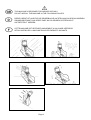
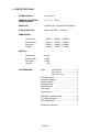
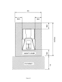
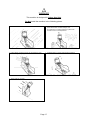
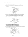
This document has been downloaded from:
The largest resource for amusement machines
documentation on the world wide web!
Operators Manual
IT IS THE RESPONSIBILITY OF THE OPERATOR TO MAINTAIN CUSTOMER SAFETY
AT ALL TIMES, AND IT IS IMPERATIVE THAT THE DETAILS SET OUT IN THIS
MANUAL ARE FOLLOWED PRECISELY.
Part No. 90500094
Page 1
G
No part of this publication may be reproduced by any mechanical, photographic or electronic process, or in the form of phonographic
recording, nor may it be stored in a retrieval system, transmitted or otherwise copied for private or public use, without permission from
NAMCO EUROPE LIMITED.
While the information contained in this manual is given in good faith and was accurate at the time of printing.
NAMCO EUROPE LIMITED reserve the right to make changes and alterations without notice.
This machine has been manufactured in accordance with European Community Directives, and has been tested and complies with
the Directives 89/336/EEC and 72/23/EEC by the application of EN55014-1, EN55014-2 and EN60335-1 standards and as such
bears the
marking. Any changes or modifications to this machine must be in accordance with the European Directives. Any
unauthorised changes to this product, may contravene such Directives.
Under some conditions of extreme external interference, e.g. radio transmissions, electrostatic discharge or mains borne transients,
some degradation of performance may occur. However the machine will recover normal performance once the source of the
interference has ceased or been removed.
Following abnormally high surges on the mains supply, the video monitor may need to be manualy reset by turning the machine OFF
and back ON.
Note:If the game processor resets due to an interuption or reduction of the mains voltage any credits established may be lost.
This game is not a machine as defined by the Machinery Directive 89/392/EEC
SAFETY WARNING
In order to use this machine safely, be sure to read this Operators Manual carefully before installation, adjustment or use of this
machine.
Whenever the owner of this machine entrusts dis-assembly, installation, adjustment or routine maintenance to another person, the
owner should ensure that that person read the appropriate precautions and relevant sections of this manual before starting work.
In order that no accidents occur when the machine is in operation, strictly follow the notes on safety as described below.
This manual along with the Installation Manual (where applicable) form an integral part of the equipment and must be available to
the operating and service personnel at all times.
This machine is for indoor use only and should only be used for the purpose intended.
Namco Ltd. bears no responsibility for accidents, injury or damage resulting from unauthorized changes to, or improper use of this
machine.
SAFETY NOTES
The following safety notes are used throughout this manual. Familiarize yourself with each of these notes and its
meaning before installing, servicing or making adjustments to this machine.
WARNING
Warning denotes a hazard that could result in injury or death. Do not proceed beyond a
warning note until the indicated conditions are fully understood and met.
CAUTION
Caution denotes a hazard that could result in damage to the machine. Do not proceed beyond a
warning note until the indicated conditions are fully understood and met.
GENERAL SAFETY CONSIDERATIONS
Only operate this machine after checking that it has been installed correctly and in accordance with the manual.
If there is an error or problem with the machine, operation must be stopped immediately and the problem
rectified before any further use.
Installation, service, adjustment or routine maintenance should be carried out by suitably qualified persons only.
For continued protection against fire hazard, replace fuses with the same type and rating. The use of other fuses
or material is prohibited.
The power supply inside the monitor will remain hot and have areas of high voltage even though the machine
has been turned OFF, and there is the possibility of burns or electric shock. Be careful not to touch these areas.
To prevent possible electric shock due to failure, this machine MUST be fitted with a securely connected
EARTHED plug.
If at any time the mains supply lead becomes damaged, it must be replaced immediately.
Do not turn the power switch ON until the machine has been installed correctly.
Before connecting the machine to the mains supply, ensure that the machine is set for the correct voltage and that the
correct fuses are fitted.
Page 2
NOTES ON INSTALLATION
NEVER turn the power to the machine ON until installation has
been completed.
In order to prevent possible electric shocks, be sure that the
machine is connected to the mains with a securely connected
earthed plug.
So that customers are not injured by the movement of the machine,
ensure that there is as least 500mm separation between other
machines or walls.
In order to avoid damage to the machine due to mis-operation, ensure
that the voltage of the mains supply is 230volts AC.
Note: If the location of this machine has a polished floor, it is recommended
that rubber pads are fitted under the level adjusters to prevent the
machine sliding on the floor.
Note: In order to gain access to the Power Supply and CPU assemblies, make
sure that the rear of the machine is separated from a wall or other
machine by at least 500mm.
MOVING THE MACHINE
This machine is fitted with castors to make it easier to move. Take care when moving the machine on an
inclined surface.
The Header Assembly has a forward centre of gravity, so it is important that at least two people are used to
fit or remove the Header Assembly.
The fitting position of the Header Assembly is high, and it is important that a means of reaching the height
safely,without stretching, is available. (e.g. Steps, Step Stool etc.)
The overall height of the machine, with the Header Assembly fitted, is 2050mm. Take care of any overhead
obstructions. (e.g. Light Fittings, Electric Cables etc.)
When moving the game, ensure that the game is dis-assembled into 3 parts: Monitor Assy, Coin Tower
and Header Assy.
REMOVING AND REPLACING PARTS
Adjustments or maintenance on this machine should be carried out by suitably qualified personnel only.
Do not make any alteration to this machine without prior approval. Doing so could cause unforeseeable
danger.
Only parts specified by Namco Europe Ltd should be used when replacing or repairing parts. (Including
screws).
Ensure that the power to the machine is turned OFF before commencing any maintenance work. (Trouble
shooting, repairs etc.)
If performing work not described in this manual, be sure to contact your distributor for instructions, as no
responsibility will be accepted for damage or injury.
Parts of the Power Supply and Monitor remain hot and carry high voltage even after switching OFF and
could cause burns or electric shock. Take care not to touch these parts accidentally.
Make sure that the machine is switched OFF before connecting or disconnecting any plugs or connectors.
When removing the mains connector from the machine, or the mains plug from the wall outlet, always
grasp the plug and not the cable.
Page 3
D
Dieses Dokument darf in keiner Weise vervielfältigt werden. Jegliche Tonaufnahmen sowie die Speicherung auf Datenträger
(Suchsysteme), die Weitergabe oder sonstiges Kopieren für den gewerblichen und privaten Gebrauch sind untersagt und
bedürfen der vorherigen Genehmigung durch NAMCO EUROPE LIMITED.
Die informationen in diesem Handbuch entsprechen den Tatsachen bei Drucklegung. NAMCO EUROPE LIMITED behält sich
jedoch das Recht zu Änderungen ohne vorherige Bekanntgabe vor.
Dieses Gerät trägt das CE-Zeichen und wurde gemäß den EU-Richtlinien produziert. Es erfüllt die Richtlinien 89/336/EEC und
72/23/EEC und Standards EN 55014, EN55104 und EN60335-1 (s. Deckblatt des Handbuches). Alle Veränderungen an diesem
Gerät müssen in Übereinstimmung mit den EU-Richtlinien erfolgen. Nicht genehmigte Veränderungen an diesem Gerät
verstoßen gegen diese Richtlinien.
Extreme äußere Störungen, wie z.B. durch Radiobetrieb, elektrostatische Entladung oder zeitweilige Netzschwankungen
können zu einer Leistungsminderung führen. Sobald diese Faktoren jedoch ausgeschaltet oder beseitigt wurden, erreicht das
Gerät seine normale Leistung.
Achtung! Falls der Spielprozessor auf Grund von Netzunterbrechungen oder Abnahme der Netzspannung aussetzt, kann es
zum Verlust von Spielkrediten kommen.
Dieses Gerät fällt nicht unter die Maschinen-Richtlinie 89/392/EEC
SICHERHEITSHINWEISE
Um einen ordnungsgemäßen Betrieb dieses Gerätes zu gewährleisten, muß vor Aufstellung, Inbetriebnahme und Gebrauch das
Handbuch sorgfältig gelesen werden.
Sobald der Besitzer dieses Gerätes die Demontage, Aufstellung, Inbetriebnahme oder den Service einer anderen Person
überträgt, muß er sicherstellen, daß diese Person vor Arbeitsbeginn die nötigen Sicherheitshinweise und die dazugehörigen
Kapitel des Handbuches liest und versteht.
Um jegliche Unfälle während des Betriebes zu vermeiden, müssen obige Hinweise strikt befolgt werden.
Dieses Handbuch sowie das spezielle Geräte-Handbuch (wenn vorhanden) gehören zum Gerät und müssen dem Betreiber und
Wartungspersonal stets zugänglich sein.
Dieses Gerät ist ausschließlich für den gewerblichen Gebrauch in geschlossenen Räumen bestimmt und darf nur dort betrieben
werden.
NAMCO LTD. übernimmt keinerlei Haftung für Unfälle, Verletzungen oder Beschädigungen, die auf nicht genehmigte
Veränderungen oder unsachgemäßen Betrieb des Gerätes zurückzuführen sind.
SICHERHEITSHINWEISE
Folgende Sicherheitsbegriffe werden im gesamten Handbuch benutzt. Machen Sie sich daher bitte vor Inbetriebnahme,
Wartung und Durchführung von Einstellungen am Gerät mit diesen Warnhinweisen vertraut.
WARNUNG
WARNUNG bezeichnet eine Gefahrenquelle für Leib und Leben. Erscheint dieser Warnhinweis,
darf erst weitergearbeitet werden, wenn die entsprechenden Erklärungen vollständig
verstanden und befolgt wurden.
VORSICHT
VORSICHT bezeichnet eine Gefahrenquelle für die Beschädigung des Gerätes. Erscheint dieser
Warnhinweis, darf erst weitergearbeitet werden, wenn die entsprechenden Erklärungen vollständig
verstanden und befolgt wurden.
ALLGEMEINE SICHERHEITSHINWEISE
Das Gerät darf nur betrieben werden, nachdem es vorschriftsmäßig und in Übereinstimmung mit dem Handbuch
aufgestellt wurde.
Die Warnschilder müssen in gutem Zustand sein und ersetzt werden, wenn sie nicht mehr gut lesbar sind.
Bei Auftreten eines Fehlers oder Problems muß das Gerät sofort abgeschaltet werden und darf erst nach
fachgerechter Behebung des Fehlers wieder in Betrieb genommen werden.
Aufstellung, Service, Einstellungen und Wartung dürfen nur von dafür qualifiziertem Fachpersonal durchgeführt
werden.
Zur Vermeidung von Feuer, defekte Sicherungen nur durch vorgeschriebene Sicherungen ersetzen. Die
Verwendung von andersartigen Sicherungen oder unterschiedlichem Material ist untersagt.
Das Netzteil im Monitor bleibt nach Ausschalten des Gerätes noch heiß und führt weiterhin Hochspannung. Daher
besteht die Gefahr von Verbrennungen und Elektroschlägen. Diese Bereiche dürfen nicht berührt werden.
Zur Vermeidung von Elektroschlägen muß dieses Gerät mit einem ordnungsgemäß geerdeten Netzstecker
versehen sein.
Bei Beschädigungen des Netzteiles muß dieses umgehend ersetzt werden.
Gerät erst nach abgeschlossener Aufstellung einschalten.
Vor Einstecken des Netzsteckers bitte sicherstellen, daß Netzspannung und Gerätespannung übereinstimmen, und die
vorgeschriebenen Sicherungen verwendet wurden.
Page 4
HINWEISE ZUR AUFSTELLUNG
NIEMALS das Gerät einschalten bevor die Aufstellung völlig
abgeschlossen ist.
Zur Vermeidung von Elektroschlägen muß das Gerät mit einem
ordnungsgemäß geerdetem Netzstecker an die Stromversorgung
angeschlossen werden.
Um zu vermeiden, daß Kunden durch die Gerätebewegungen
verletzt werden, muß ein Sicherheitsabstand zu anderen Geräten
und Wänden von mindestens 50cm eingehalten werden.
Zur Vermeidung von Beschädigungen durch Fehlbetrieb am Gerät
sicherstellen, daß die Netzspannung 230 Volt beträgt.
Hinweis: Ist das Gerät für einen Aufstellplatz mit glattem Fußboden bestimmt,
müssen die Standbeine mit Gummiplättchen unterlegt werden, damit das
Gerät fest steht und nicht auf dem Boden hin- und herrutscht.
Hinweis: Zu Reparaturzwecken am Netzteil und den CPU-Komponenten muß die
Rückseite des Gerätes mindestens 50cm von anderen Geräten und der
Wand entfernt sein.
Zum leichteren Transport ist das Gerät mit Rollen ausgerüstet. Daher besondere Vorsicht auf
abschüssigem Boden
Der Schwerpunkt des Aufsatzes liegt sehr weit vorn. Daher werden für den Ab- und Aufbau des Aufsatzes
mindestens 2 Personen benötigt.
Der Aufsatz wird in großer Höhe montiert. Daher muß aus Sicherheitsgründen eine Steighilfe, wie z. B.
eine Leiter, ein Tritt oder ähnliches, verwendet werden.
Die Gesamthöhe de Gerätes beträgt 2.05m. Daher Vorsicht bei tiefer hängenden Beleuchtungskörpern.
Für den Transport oder bei einem Platzwechsel Gerät in drei Teile zerlegen: Kopfteil, Vorderteil, und
Fahreinheit
AUS- UND EINBAU VON KOMPONENTEN UND TEILEN
Aufstellung, Service, Einstellung und Wartung dürfen nur von dafür qualifiziertem Fachpersonal
durchgeführt werden.
Es dürfen keierlei Veränderungen ohne vorherige Genehmigung am Gerät vorgenommen werden.
Zuwiderhandlungen stellen eine Gefahrenquelle dar.
Für die Repartur dürfen nur Originalersatzteile (incl. Schrauben) von NAMCO EUROPE LTD. verwendet
werden.
Vor Beginn aller Wartungsarbeiten (Fehlersuche, Reparaturen etc.) muß der Netzstecker gezogen
werden.
Bei Arbeiten, die nicht in diesem Handbuch beschrieben werden, muß vorher der Händler zu Rate
gezogen werden, da sonst keinerlei Haftung bei Beschädigungen und Verletzungen übernommen wird.
Teile des Netzteiles und Bilschirmes bleiben nach Abschalten noch heiß und führen Hochspannung. Dies
kann zu Verbrennungen oder einem Elektroschlag führen. Diese Teile dürfen nich berührt werden.
Vor der Montage oder dem Entfernen von Steckverbindungen und Steckern muß das Gerät ausgeschaltet
werden.
Bei Ziehen des Gerätesteckers oder des Netzsteckers aus der Wandsteckdose stets den Stecker greifen
und nicht das Kabel.
Page 5
F
Aucun élément de cette publication ne sera reproduit, ni par procédé mécanique, photographique ou électronique, ni par un
moyen d’enregistement phonographique. Ces informations ne seront ni stockées grâce à un procédé de récupération, ni
transmises ou autrement copiées pour un usage publique ou privé, sans l’autorisation de NAMCO EUROPE LIMITED.
Malgré le fait que les informations contenues dans ce manuel soient données de bonne foi et étaient actualisées au moment de
leur impression, NAMCO EUROPE LIMITED se réserve le droit de procéder à des changements ou à des modifications sans
avis préliminaire.
Ce jeu a été fabriqué en respect des normes de la Communauté Européenne, après avoir été testé il répond aux normes 89/
336/EEC et 72/23/EEC, en application des standards EN55014, EN55104 et EN60335-1 (voir la couverture du manuel), et
comme tel il comporte l’autocollant de conformité avec les normes de la Communauté Européenne. Tout changement non
autorisé sur ce produit pourrait contrevenir à ces normes.
Sous certaines conditions extrêmes d’interférence exteme, par example des transmissions radio, des décharges
électrostatiques ou bien de interférences passagères sur le réseau, certaines dégradations ou anomalies peuvent se produire.
Le jeu retrouvera cependant son état normal de fonctionnement lorsque la cause de ces anomalies aura cessé ou se trouvera
déplacée.
Note:Si le processeur du jeu se reprogramme suite à une interruption ou une réduction de l’alimentation, les crédits qu’il aurait pu
contenir peuvent se trouver perdus.
Ce jeu n’est pas une machine, telle que définie par la norme sur les machines 89/392/EEC
MESURES DE SECURITE
Afin d’utiliser ce jeu en toute sécurité, bien lire ce manuel d’utilisation avant de procéder à son installation, son réglage ou son
exploitation.
Si le propriétaire de ce jeu en confie la démontage, l’installation, le réglage ou la maintenance habituelle à une autre personne,
il devra s’assurer que cette personne ait lu les conseils d’utilisation et les passages du manuel se rapportant à ce thème, avant
qu’elle ne commence son travail.
Afin d’éviter tout accident pendant la durée d’exploitation de ce jeu, se conformer strictment aux conseils de sécurité décrits à la
suite.
Ce manuel ainsi que le manuel d’installation du jeu (là où nécessaire) font partie des éléments nécessaires à l’installation de la
machine et doivent être mis à la disposition de l’utilisateur et du personnel de maintenance à tout moment.
Ce jeu est uniquement destiné à un usage intérieur et devra être utilisé comme tel.
Namco Ltd. ne sera aucunement tenu responsable en cas d’accidents, de blessure ou de dommage quelconque résultant de
modifications non autorisées ou d’usage impropre du jeu.
REMARQUES SUR LA SECURITE
Les termes de sécurité détaillés à la suite seront utilisés tout au long de la lecture de ce manuel. Il convient de vous
familiariser aves chacun de ces termes ainsi que leur signification avant de procéder à l’installation, à la maintenace ou au
réglage du jeu.
AVERTISSEMENT
Ce terme annonce un danger qui pourrait éventuellement avoir des conséquences
dommageables ou mortelles. Ne pas passer oûtre ce signal jusqu’à ce que les conditions indiquées soient
entiérement comprises et effectuées.
ATTENTION
Ce terme indique qu’un danger menace la machine. Ne pas passer oûtre ce signal jusqu’à ce que les
conditions indiquées soient entiérement comprises et effectuées.
CONSIGNES GENERALES DE SECURITE
Allumer l’appareil seulement après avoir vérifié qu’il a été correctement installé, et que les instructions du
manuel ont été respectées.
Les notes de mise en garde doivent constamment demeurer en bon état et être remplacées en cas de
disparition, afin que le client puisse les lire clairement.
S’il y una erreur ou un problème avec la machine, l’utilisation doit être immédiatement interrompue et le
problème résolu avant toute nouvelle utilisation.
L’installation, le service, le réglage, ou la maintenance doivent être effectués uniquement par les personnes
qualifiées.
Afin d’éviter un éventuel incendie, s’assurer que les fusibles soient remplacés par le même type de fusibles et
au bon voltage. L’utilisation d’autres sortes de fusibles ou autres matériels est interdite.
L’alimentation à l’intérieur du moniteur reste chaude et comporte des zones de haute tension même si la
machine est éteinte. Il existe donc un risque de brúlure ou d’électrocution. Attention à ne pas toucher ces
endroits.
Pour prévenir une éventuelle électrocution due à un défaut matériel, ce jeu DOIT être muni d’une prise de
TERRE connectée en toute sécurité
Si à tout moment les fils électriques sont endommagés, il faut les remplacer immédiatment
Ne pas mettre le jeu en mode de fonctionnement avant qu’il n’ait été correctement installé.
Avant de connecter la machine au réseau, s’assurer que la machine est installée sous la bonne tension et que les
fusibles correspondent.
Page 6
NOTES D’INSTALLATION
NE JAMAIS mettre le jeu en marche avant que
l’installation ne soit complétement effectuée.
Afin de prévenir une éventuelle électrocution, s’assurer
que la machine est connectée au réseau avec une prise
de terre reliée selon les normes de sécurité.
Afin que les clients ne soient pas blessés par les
mouvements du jeu, s’assurer qu’il existe au moins 500
mm de séparation aves les autres jeux ou les murs.
Afin d’éviter que la machine ne soit abimée suite à une
mauvaise opération, s’assurer que la tension sur le réseau
principal soit de 230 volts AC.
Note: Si l’endroit où doit être installée la machine à un sol pôli, il
est recommandé de poser des tampons feutrés sous les
vérins pour éviter que le jeu ne glisse sur le sol
Note: Afin de facilité l’accès aux CPU at à l’alimentation,
s’assurer qu’il y a un espace d’au moins 500 mm entre
l’arrière du meuble et le mur ou tout autre jeu.
Le jeu est foumi avec des roulettes pour une meilleure mobilité. Prendre garde quand la
machine est déplacée sur une surface inclinée.
Le centre de gravité de la partie supérieure du jeu est situé sur l’avant, il est donc
indispensable que deux personnes au moins soient employées pour installer ou déplacer la
partie supérieure.
L’installation de la partie supérieure du jeu s’effectue en hauteur, il est donc important d’utiliser
un élevateur quelconque pour en effectuer le montage.
La hauteur totale de l’assemblage principal est de 2050 mm, prendre garde aux encombrements
de la partie supérieure (ex : illuminations du bandeau).
Quand le jeu est déplacé ou transporté, s’assurer qu’il est séparé en 3 parties: l’assemblage du
haut (le bandeau), l’assemblage de devant (la cabine), l’assemblage mobile.
DEPLACER ET REMPLACER LES UNITES ET LES PIECES DETACHEES.
L’installation, le service, le réglage, ou la maintenance doivent être effectués uniquement par
les personnes qualifiées.
Ne pas apporter de modifications sur cette machine sans autorisation préalable, faute de quoi
cela pourrait entraîner un danger.
Seules les pièces détachées Namco Europe Ltd. doivent être utilsées pour le remplacement ou
la réparation de pièces (y compris les vis)
S’assurer que l’interrupteur soit sor OFF avant de commencer tout travail de maintenance
(localisation d’une panne, rèparations, etc.)
Si dans ce manuel il manque une information pour réaliser un quelconque travail, contacter
votre distributeur, car aucune responsabilité ne sera acceptée en cas de domage ou de
blessure.
Les pièces de l’alimentation et du moniteur restent chaudes, à tension élévée même lorsque la
machine est hors tension, elle pourrait occasionner des brûlures ou des électrocutions.
Attention de ne pas toucher ces endroits accidentellement.
S’assurer que la machine soit hors tension avant de brancher ou débrancher toute prise ou
connecteur.
Lorsque l’on manipule la prise au réseau de la machine, ou lorsque les prises principales
doivent être débranchées, saisir toujours la prise, et non le câble.
Page 7
t
D
F
THIS MACHINE IS DESIGNED FOR INDOOR USE ONLY.
DO NOT INSTALL THE MACHINE IN THE FOLLOWING PLACES.
DIESES GERÄT IST NUR FÜR DIE GEWERBLICHE AUFSTELLUNG IN GESCHLOSSENEN
RÄUMEN BESTIMMT. DAS GERÄT DARF AN FOLGENDEN PLÄTZEN NICHT
AUFGETSTELLT WERDEN.
CETTE MACHINE EST DESTINEE UNIQUEMENT A UN USAGE INTERIEUR.
NE PAS INSTALLER LA MACHINE DANS LES ENDROITS SUIVANTS.
Page 8
1. SPECIFICATIONS
POWER SUPPLY :-
230volts AC
AMBIENT OPERATING
TEMPERATURE:-
+5°C
MONITOR :-
Hantarex 28" Polo with Auto Degauss
COIN ACCEPTOR:-
Mars CashFlow - 1 Channel
to
+25°C
DIMENSIONS :Assembled
970(w) x 1800(d) x 2220(h)
Monitor Assy
Step Assy
Header
970(w) x 910(d) x 1800(h)
970(w) x 890(d) x 1200(h)
660(w) x 375(d) x 420(h)
WEIGHT :Assembled
243kg
Monitor Assy
Step Assy
Header
135kg
105kg
3kg
ACCESSORIES :-
Keys:
(Cash Door) ............................ 2
(Coin Door) ............................. 2
(Service Door) ......................... 2
IEC Mains Lead ............................................ 1
Operators Manual ......................................... 1
Monitor Manual ............................................. 1
Cashflow Data .............................................. 1
Potentiometer ............................................... 1
Link Cable .................................................... 1
Joint Bracket................................................. 2
M10x25 Hex Head Screw ............................. 8
M10 Spring Washer ..................................... 8
M10 Flat Washer .......................................... 8
M5 Security Wrench ..................................... 1
Page 10
2. HOW TO PLAY
This game is based on Alpine ski racing.
The player stands on the steps and moves them left or right to control the skier.
By using the inner edge when moving the steps, the skier slows down and turns
quickly.
SINGLE PLAY
•
Race Mode
The player races the computer skiers and the object is to cross the goal line first.
The game is over when the player crosses the finish line within the given time
period, or the time period reaches zero. The time period is increased each time a
player passes a check point.
If a player wins in a fast time they can enter their initials. Select letters using the
select buttons and enter them by using the decision (Viewpoint) button.
•
Time-Trial Mode
The object of the game is to pass between the flags (gates) and to cross the
finish line in the fastest time. The rules require the player to go through the gates,
so more technique is needed for this mode than the normal race mode.
The game is over when the player crosses the finish line within the given time
period, or the time period reaches zero. The time period is increased by one
second each time a player passes through a gate.
If a player completes a course in a fast time they can enter their initials. Select
letters using the select buttons and enter them by using the decision (Viewpoint)
button.
A player is not disqualified for not passing through a gate, however the player will
not be able to enter their initials even if they cross the finish line in a good time.
LINKED PLAY
When two games are linked, players on each game will be able to race against
each other on the same course. When sufficient credit has been established and
the start button has been pressed on one game, there is a time period before the
start of the game during which another player can establish credit and press the
start button on the other game to enable linked play
•
Linked Race Mode
The object of the game is to cross the goal line before the opponent.
The game is over when the player crosses the finish line within the given time
period, or the time period reaches zero. The time period is increased each time
the leading player passes a check point.
If a player wins in a fast time they can enter their initials. Select letters using the
select buttons and enter them by using the decision (Viewpoint) button.
•
Linked Time-Trial Mode
The object of the game is to pass between the flags (gates) and to cross the
finish line faster than the opponent. No penalty time is given for touching the
opposing skier.
The game is over when the player crosses the finish line within the given time
period, or the time period reaches zero. The time period is increased by one
second each time a player passes through a gate.
If a player completes the course in a fast time, they can enter their initials. Select
letters using the select buttons and enter them by using the decision (Viewpoint)
button.
A player is not disqualified for not passing through a gate, however the player will
not be able to enter their initials even if they cross the finish line in a good time.
Page 11
GAME SELECTION
•
Skier Selection
After inserting sufficient credit, the "Skier Selection Mode" will be displayed. The
player selects one of three skiers, "Basic", "Mogul" or "Downhill" by using the L/R
select buttons and pressing the decision (Viewpoint) button
•
Game Mode Selection
After the Skier Mode has been selected, the "Game Mode Selection" screen is
displayed. The player selects either the "Race Mode" or "Time-Trial Mode" by
using the L/R selection buttons, and pressing the decision (Viewpoint) button.
Linked Time-Trial Mode is only available if both players select Time-Trial Mode
•
Course Selection
After the game mode has been selected, the "Course Selection" screen is
displayed.
The player can select either the "Hi-Speed Course" or the "Technical Course" by
using the L/R selection buttons, and pressing the decision (Viewpoint) button.
When in linked mode, the Technical Course is only available if both players select
the Technical Course.
•
Viewpoint Selection
The viewpoint button can be pressed at any time during a game to switch
between the views.
Third Persons View: This is the view as seen by a third person. This view can be
used to get an understanding of the surrounding conditions.
The game normally starts in this view.
Players View:
This is the view as seen by the skier. This provides an
exciting view while skiing.
Behind View:
This is the view from just behind the skier. This view can be
used to get an understanding of the skiers posture.
GAME RULES
•
Single Race Mode
The player races against four computer skiers.
The game will finish when the player crosses the finishing line within the given
time period.
The time period is increased each time a checkpoint is reached.
If the time period reaches zero before the player has completed the course, the
player will stop, the result will be displayed and the game is over.
•
Linked Race Mode
The players on two machines will race against each other.
The game will finish when the player crosses the finishing line within the given
time period. Both players can finish the course if they have sufficient time.
The time period is increased each time a checkpoint is reached by the leading
player and the extra time is added to both players.
If the time period reaches zero before the player has completed the course, the
player will stop, the result will be displayed and the game is over.
Page 12
•
Single Time-Trial Mode
The object of the game is to pass between the flags (gates) in the fastest time.
The game is over when the player crosses the finish line within the given time
period, or the time period reaches zero. The time period is increased by one
second each time a player passes through a gate.
•
Linked Time Trial Mode
The game is over when the player crosses the finish line within the given time
period, or the time period reaches zero. The time period is increased by one
second each time a player passes through a gate.
If the distance between each skier becomes too close, the opponent will
disappear from the screen and return when there is a greater distance between
the skiers.
The time period is not linked and the one second bonus for passing through a
gate is only given to the player passing through the gate, so it is possible for the
game to be over sooner for one player than the other.
At game over a three second penalty will be added to a player's finishing time for
each gate that the player has missed.
If both players complete the course in the given time, the player with the fastest
time, including penalties, is the winner.
Page 13
3. MAJOR COMPONENTS
Page 14
4. MOVING THE MACHINE
WARNING
•
This machine is fitted with castors to make it easier to move.
Take care when moving the machine on an inclined surface.
•
The Header Assembly has a forward centre of gravity, so it
is important that at least two people are used to fit or remove
the Header Assembly.
•
The fitting position of the Header Assembly is high, and it is
important that a means of reaching the height safely, without
stretching, is available. (e.g. steps, step stool etc.)
•
The overall height of the machine, with Header assembly
fitted, is 2200mm, take care of any overhead obstructions
e.g. light fixtures.
5. INSTALLATION
Notes on Installation
WARNING
•
NEVER turn the power to the machine ON until installation
has been completed.
•
In order to prevent possible electric shocks, be sure that the
machine is connected to the mains with a securely connected
earthed plug.
•
So that customers are not injured by the movement of the
Ski Steps, ensure that there is at least 500mm separation
between other machines or walls.
CAUTION
•
In order to avoid damage to the machine due to mis-operation,
ensure that the voltage of the mains supply is 230volts AC.
NOTE
•
If the location site of this machine has a polished floor it is
recommended that rubber pads are fitted under the level adjusters
to prevent the machine sliding on the floor.
•
In order to gain access to the Power Supply and CPU assemblies,
make sure that the rear of the machine is separated from a wall
or other machine by at least 500mm.
•
When installation is complete, it is imperative that the game is
initialized. (See section 6-5 page 21)
Page 15
Page 16
WARNING
This machine is designed for Indoor Use Only
Do Not install the machine in the following places.
1. Outdoors
2. Direct sunlight, places with excessive humidity or dust,
places where there is water leakage, near
air-conditioning or heating equipment, places with
excessive heat or cold temperature.
3. Places where it would be in the way of emergency exits
or fire extinguishing equipment.
4. Unstable places or places with excessive vibration.
5. Places that are not level.
Page 17
5-1 Assembling the Machine
1.
Remove 4off Security Screws (M5x16) and remove the Clamp Bracket Vac-Form
from the front of the monitor cabinet.
2.
Remove the 4off Hex Head Screws (M10x20), Spring Washers and Flat
Washers.
3.
Note: Do not loose the Vac-Form or screws as they are needed for refitting.
Remove 4off Hex Head Screws (M10x20), Spring Washers and Flat Washers
and remove the Ski Pole Clamp Bracket from the Shipping Bracket.
Note: Do not loose the Bracket or screws as they are needed for refitting.
4.
Remove 2off Hex Head Screws (M10x20), Spring Washers and Flat Washers
5.
and remove the Shipping Bracket from the Step Base.
Connect the 2 connectors between the Step Base and Monitor Base and push
the two bases together, taking care not to trap any wires.
6.
Fit the Joint Brackets using the 8off Hex Head Screws (M10x25), Spring Washers
and Flat Washers. (4off screws each side)
Page 18
6.
Refit the Clamp Bracket using the 8off Hex Head Screws (M10x20), Spring
Washers and Flat Washers so that the Ski Pole Joint Bar is clamped securely to
the Monitor Cabinet.
7.
Refit the Clamp Bracket Vac-Form using the 4off Security Screws (M5x16)
NOTE:When the machine is fully assembled and in its final position, lower the 8 level
adjusters, with a spanner, so that all castors are raised from the floor by
approximately 5mm, and the machine is level. Tighten the lock nuts with a
spanner to ensure that the level adjusters do not move.
If this machine is installed on a smooth or shiny floor, it is recommended that rubber
slip mats be placed under each adjustable foot to prevent the machine from moving
when being played.
Page 19
5-2 Fitting the Header Assembly
The Header Assembly has a forward centre of gravity, so it is important that at
least two people are used to fit or remove the Header Assembly.
The fitting position of the Header Assembly is high and it is important that a means of
reaching the height safely, without stretching, is available. (e.g. steps, step stools etc)
1.
Remove the two security screws
(M5x12) and remove the
Connector Cover.
2.
Place the Header Assembly on to the monitor cabinet, slide
the header back ensuring that it engages fully in to the
retaining brackets at the front of the monitor cabinet.
3.
Fit the two security head
screws (M5x12) to retain the
Header Assembly to the
cabinet.
4.
Connect the connector
and refit the connector
cover using the two
security screws
(M5x12).
Page 20
6. ADJUSTMENTS
6-1 Turning on the Power
After the machine has been installed, turn ON the power. The power switch is
located on the rear of the monitor cabinet.
6-2 Adjustment Switches
The Adjustment switches are located inside the coin door.
1.
Service Switch.
Press this switch to obtain game credits without incrementing the play meter.
2.
Test Switch
Slide the test switch ON to enter test mode.
Test mode allows testing and the changing of game settings. (Refer to section
6-3 "Test Mode" (page 11))
COIN COUNTER
LEFT PLAYER
TEST
RIGHT PLAYER
SERVICE
TEST
Service Bracket
Page 21
SERVICE
6-3 Test Mode
1.
Open the coin door and slide the test switch "ON". The menu screen will be
displayed on the monitor.
2.
Select the test required by pressing the 'Left or Right Selection' push button. The
selected test will 'blink'.
3.
Enter the selected test by pressing the 'Decision' push button. Select "EXIT" to
return the "Menu Screen".
4.
After testing is completed, ensure that the test switch is returned to the "OFF"
position to return to normal game mode.
The Test Switch must always be in the "OFF" position for normal game mode.
MENU
COIN OPTIONS
-----------------
(1) Sets the price of play (See 6-3-1)
GAME OPTIONS
-----------------
(2) Sets the game options (See 6-3-2)
I/O TEST
-----------------
(3) Used for testing switches and controls
(See 6-3-3)
MONITOR TEST
-----------------
(5) Used for adjusting the monitor
(See 6-3-5)
SOUND TEST
-----------------
(4) Used for testing sound and setting
volumes (See 6-3-4)
ADS TEST
-----------------
(6) Displays accumulated game data
(See 6-3-6)
OTHERS
-----------------
(7) Used for testing the PC Boards and for
initializing all of the settings
(See 6-3-7)
: CHOOSE
: ENTER
View Change
Select L/R Buttons
Page 22
6-3-1
1.
2.
3.
4.
Coin Options
Select item (1) "COIN
OPTIONS" on the menu
screen to set the game
cost and related settings.
Press 'Select L/R' to
select the required item.
Use the 'Decision' button
to adjust the settings.
COIN OPTIONS
[ DEFAULT IN GREEN ]
GAME COST
1 COIN
FREE PLAY
Select "EXIT" to return to
the menu screen.
1 CREDIT
---------------- (a)
OFF
---------------- (b)
EXIT
: CHOOSE, CHANGE
: ENTER
Note :- The price of play on this machine is set within the Cashflow Coin Mech.
Ensure that the Coin Options on the screen are set as shown in the
following table.
ITEM
CONTENTS
(a) Game Cost No of Coins required for No. of credits - - - - - - settable 1 - 9
(b) Free Play
Yes/No
FACTORY SET
1 Coin 1 Credit
NO
Page 23
6-3-2
Game Options
1.
Select item (2) "GAME OPTIONS" on the menu screen to set the game
options and related settings.
2.
Press 'Select L/R' to select the required item.
3.
Press the 'Decision' button to adjust the settings. Standard settings are
displayed in green.
4.
Select "EXIT" and press 'Decision' to return to the menu screen.
GAME OPTIONS
[ DEFAULT IN GREEN ]
ID No.
0 LEFT
GAME DIFFICULTY
SOUND IN ATTRACT
HI SCORE INITIALIZE
LINK OFF ---------- (a)
C
---------- (b)
ON
---------- (c)
---------- (d)
EXIT
: CHOOSE/CHANGE
ITEM
: ENTER
DESCRIPTION
(a) ID No
Sets machine as left or right when in linked mode
(b) Game Difficulty
A (easy) to C (hard)
(c) Sound in Attract
On / Off
(d) Hi Score Initialize
Yes / No
FACTORY SET
0 Left
B
On
(If Yes Hi Score will be reset when exiting test)
Page 24
No
6-3-3
I/O Test
1.
Select item (3) "I/O Test" on the menu screen to test the switches, motor
and step adjust.
2.
Press 'Select L/R' to select the required item, then press the 'Decision'
button to enter the test.
3.
Select "EXIT" and press the 'Decision' button to return to the menu screen.
I/O TEST
DIP 4
12345678
LINK OFF
SWITCH TEST
MOTOR TEST
LAMP TEST
STEP ADJUST
EXIT
: CHOOSE
............................(a)
............................(b)
............................(c)
............................(d)
............................(e)
............................(f)
: ENTER
(a) Shows condition of DIP SW 4 on the PCB. In normal operation all switches
are OFF. (If a switch is ON, it will be displayed in red.)
(b) Displays whether machine is linked. (See 6-4 )
(c) For testing Switches and Control Pots. (See 6-3-3-1)
(d) Not used on this machine.
(e) For testing the pushbutton lamps. (See 6-3-3-2)
(f)
For initializing the Step Control Pots. (See 6-3-3-3)
Page 25
6-3-3-1
1.
Switch Test
Select Switch Test from the 'I/O Test' menu. The following screen will
appear on the monitor.
SWITCH TEST
TEST SW
ON
.................(a)
COIN SW
ON
.................(b)
SERVICE SW ON
.................(c)
L SELECTION BUTTON
ON ............(d)
VIEW CHANGE BUTTON ON ............(e)
R SELECTION BUTTON
ON ............(f)
SWING 0000 0000 CENTER .........(g)
EDGE
0000 0000 CENTER .........(h)
+
2.
+
: EXIT
The word 'ON' will appear next to items (a) to (f) each time the
respective switch is operated.
When the skis are pushed left, 'SWING-CENTRE' will change to 'LEFT'
and 'OK' will appear just before it reaches the extreme left,. When the
skis are pushed right, 'CENTRE' will change to 'RIGHT' and 'OK' will
appear just before it reaches the extreme right. '0000' will increase
when the skis are moved to the right and decrease when they are
moved to the left.
When the skis are tilted, 'EDGE-CENTRE' will change to 'LEFT or
RIGHT' and 'OK' will appear just before they are fully tilted. '0000' will
change as the skis are tilted.
Note: "EDGE" 'OK' will only appear if you stand and
apply weight to the edges of the ski steps.
There is no problem if 'OK' is not displayed
when standing on the steps in the same way
as normal play.
3.
If 'OK' is not displayed when the edge is tilted left or right, re-initialize as
described in section 6-5 "Initialization After Replacing Parts".
4.
Operate both of the 'Select L/R' buttons and 'Decision' button together
to exit and return to the 'I/O Test' menu screen.
Page 26
6-3-3-2
1.
Lamp Test
Select Lamp Test from the 'I/O Test' menu.
On entering 'LAMP TEST' the View Change and Select switch lamps will
illuminate in sequence and the relevent lamp name will be displayed on
the monitor.
6-3-3-3
1.
Step Adjust
Select Step Adjust from the 'I/O Test' menu. The following screen will
appear on the monitor.
STEP ADJUST
SWING
EDGE
0000h
0000h
AD0
AD1
0000h
0000h
CENTER
CENTER
INITIALIZE COMPLETED
PUSH SERVICE SWITCH TO RESET
: EXIT
2.
Ensure that the skis are in the centre and level, then press the service
button. 'INITIALIZE COMPLETE' will appear on the monitor display.
3.
Select EXIT to return to the Main Menu Screen.
Page 27
6-3-4
Sound Test
1.
Select item (4) "Sound Test" on the menu screen to test the sound and
speakers.
2.
The following screen will appear on the monitor.
SOUND TEST
VOLUME L SP
(0-63)
R SP
(0-63)
SOUND IN ATTRACT
ATTRACT VOLUME
L SP
(0-63)
R SP
(0-63)
REQUEST SONG No.
MESSAGE:
32
32
ON
------------------- (a)
------------------- (b)
------------------- (c)
32
32
0
------------------- (d)
------------------- (e)
------------------- (f)
EXIT
: CHOOSE
: ENTER
3.
Select the required item by 'Select L/R' buttons. The selected item will
‘blink’.
4.
Pressing the Decision button will cause the selected value setting to blink.
5.
Pressing 'Select R' will increase the value and 'Select L' will decrease the
value.
6.
Press ‘Decision’ button to return to item select mode.
7.
When selecting the 'Request Song No.' test, 'Select R' button will increase
the song number and 'Select L' will decrease the number. The 'View
Change' button will produce the sound of the song number selected.
(Request Song 01 will produce a stereo sound test. Sound will be produced
from the speakers in the following order:- Left speaker, Right speaker, Both
speakers)
8.
Press both Select L/R buttons and View Change button together to return to
Sound Test Menu from Request Song No. Test
Item
Description
Factory Set
a
Set left speaker volume
------
00 Quietest - 63 Loudest
32
b
Set right speaker volume
------
00 Quietest - 63 Loudest
32
c
Select sound for testing. Each number will produce a different sound. 01 will
generate a stereo test.
Page 28
---
6-3-5
Monitor Test
1.
Select item (5) “Monitor Test” on the menu screen to set up and adjust the
monitor.
2.
On entering monitor test, the screen will display one of the following test
patterns.
GRADATION PATTERN
CROSSHATCH
CROSSHATCH
WHITE WINDOW
WHITE WINDOW
WHITE WINDOW
INTERLACE PATTERN
VIEW ANGLE ADJUST
VIEW ANGLE ADJUST
FULL WHITE
GREEN
WHITE
(H)
(M)
(L)
(CRT)
(PROJECTOR)
3.
Use 'Select L/R' buttons to change to the next pattern and 'Decision' button
to return to the Main Menu.
4.
Refer to monitor manual for monitor adjustments.
6-3-6
ADS Data
1.
Select item (6) "ADS Data" on the menu screen to view machine history
details.
2.
The following screen will appear on the monitor.
ON TIME
PLAY TIME
1RS
1RL
1TS
1TL
2RS
2RL
2TS
2TL
TOTAL PLAY
AVERAGE
ADS CLEAR
NEXT PAGE
EXIT
ADS 1/2
Hrs
Mins
XX
XX
XX
XX
XX
XX
XX
XX
XX
XX
XX
XX
XX
XX
XX
XX
XX
XX
XX
XX
0000
XXMins
NO
: CHOOSE
Secs
XX
XX
XX
XX
XX
XX
XX
XX
XX
XX
3. This page displays total time
that the machine has been
switched on, total playing times of
single and linked games for
downhill and slalem courses, total
number of games played and
average game time.
4. If ADS 'YES' is selected, all
ADS Data will be reset.
XXSecs
5. If 'Next Page' is selected, the
following screen will be displayed.
: ENTER
Page 29
ADS 2/2
BASICS1
1RS
1RL
1TS
1TL
2RS
2RL
2TS
2TL
MOGUL
1RS
1RL
1TS
1TL
2RS
2RL
2TS
2TL
RACER
1RS
1RL
1TS
1TL
2RS
2RL
2TS
2TL
S2
XX
XX
XX
XX
XX
XX
XX
XX
S3
XX
XX
XX
XX
XX
XX
XX
XX
S4
XX
XX
XX
XX
XX
XX
XX
XX
S5
XX
XX
XX
XX
XX
XX
XX
XX
S6
XX
XX
XX
XX
XX
XX
XX
XX
S7
XX
XX
XX
XX
XX
XX
XX
XX
GOAL
XX
XX
XX
XX
XX
XX
XX
XX
XX
XX
XX
XX
XX
XX
XX
XX
XX
XX
XX
XX
XX
XX
XX
XX
XX
XX
XX
XX
XX
XX
XX
XX
XX
XX
XX
XX
XX
XX
XX
XX
XX
XX
XX
XX
XX
XX
XX
XX
XX
XX
XX
XX
XX
XX
XX
XX
XX
XX
XX
XX
XX
XX
XX
XX
XX
XX
XX
XX
XX
XX
XX
XX
XX
XX
XX
XX
XX
XX
XX
XX
XX
XX
XX
XX
XX
XX
XX
XX
XX
XX
XX
XX
XX
XX
XX
XX
XX
XX
XX
XX
XX
XX
XX
XX
XX
XX
XX
XX
XX
XX
XX
XX
XX
XX
XX
XX
XX
XX
XX
XX
6.
This screen displays the the position on the course that the player reached
at game over for single and linked game, downhill and slalem and each
racer.
7.
Pressing the View Change button will return the screen to the ADS 1 page.
6-3-7
Others
1.
Select "Others" on the menu screen and press the View Change button.
This screen is used to test the PCB and to reset the game to factory
settings.
Page 30
6-4 Linking Two Machines
1.
Ensure that the power is "OFF"
2.
Loosen the two pozi head screws retaining the link cover bracket, located next to
the mains-in socket on the rear of the monitor cabinet, and remove the link cover
bracket.
3.
Set the slide switch on the link board to 'EXT' on both machines.
4.
Use the supplied link cables to connect each link board. (See Diag.)
Ext
IN
5.
Ext
Int
IN
OUT
Int
OUT
Turn the power to each machine "ON", and set the PCB ID using the test mode.
(Refer to section 6-3-2 "Setting the Game Options" - page 13)
Note:- Set the left machine ID to 0 / LEFT and the right hand machine ID to
1 / Right. Settings other than this will cause the machine to operate incorrectly
6.
Refit the link cover bracket and tighten the pozi head screws.
If the machines are used as single, non linked games ensure that the link cables
are removed and the slide switch is returned to the "INT" position.
Page 31
6-5 Initialization After Replacing Parts
Initialization must be performed after replacing the game PC board, Rom or Step
Controls. If initialization is not performed, the game will not function correctly.
During initialization, ensure that the step edges are level.
1.
2.
3.
Select Step Adjust from the 'I/O Test' menu. The following screen will appear on
the monitor.
Ensure that the skis are in the centre and level, then press the service button.
'INITIALIZE COMPLETE' will appear on the monitor display.
Select EXIT to return to the Main Menu Screen.
STEP ADJUST
SWING
EDGE
0000h
0000h
AD0
AD1
0000h
0000h
CENTER
CENTER
INITIALIZE COMPLETED
PUSH SERVICE SWITCH TO RESET
: EXIT
Page 32
7. MAINTENANCE
GB
In order to prevent injury or electric shock to service personnel, ensure that
the MAIN POWER IS OFF before attempting any maintenance.
Before performing any work not described in this manual, be sure to contact
your distributor to receive instructions or answers to questions.
D
Vor Beginn aller Wartungsarbeiten (Fehlersuche, Reparaturen etc.) muß der
Netzstecker gezogen werden.
Bei Arbeiten, die nicht in diesem Handbuch beschrieben werden, muß vorher
der Händler zu Rate gezogen werden, da sonst keinerlei Haftung bei
Beschädigungen und Verletzungen übernommen wird.
F
S’assurer que l'interrupteur soit sor OFF avant de commencer tout travail de
maintenance (localisation d'une panne, rèparations, etc.)
Si dans ce manuel il manque une information pour réaliser un quelconque
travail, contacter votre distributeur, car aucune responsabilité ne sera
acceptée en cas de domage ou de blessure.
SF
Varmista, että laite on kytketty POIS PÄÄLTÄ ennen työn aloittamista.
Ota yhteyttä maahantuojaan ohjeita varten, jos joudut tekemään työtehtäviä,
joita ei ole esitelty huoltokirjassa, muuten vastuuta vioista tai
loukkaantumisista ei ole.
7-1 Replacing the Push Button Switch or Lamp
1.
Remove the ten security head screws (M5x12)
and remove both side vac-forms.
2.
Remove the four security head screws (M5x12)
and remove the play panel only sufficient to
disconnect the connector, taking care not to
strain any wires.
Page 33
3.
Remove the lamp/switch assembly by
pulling it away from the switch body.
Replace the lamp or switch.
7-2 Replacing the Fluorescent Tube
1)
Remove the two security head screws (M5x12) and remove the acrylic retaining
bracket.
2)
Remove the header acrylic
3)
Replace the fluorescent tube.
4)
Reassemble in reverse order.
Warning
The fluorescent tube may be hot take care when handling the tube.
Page 34
7-3 Replacing the Edge Potentiometer
1.
Remove the four security head screws (M5x12) and remove the step front vacform.
2.
Remove the two hex head screws (M6x16) and remove the cover plate.
3.
Disconnect the potentiometer connector.
4.
Loosen the hex socket head set screw and remove the potentiometer complete
with bracket.
5.
Replace the potentiometer taking care that the wires are re-soldered to the
correct terminals.
Note: Ensure that the lug on the potentiometer is engaged in the hole in the bracket
when refitting the potentiometer.
Page 35
7-4 Replacing the Swing Potentiometer
1.
Remove the four security head screws (M5x12). Loosen the two security head
screws (M5x12) and remove the base front cover.
2.
Disconnect the potentiometer connector.
3.
Loosen the hex socket head set screw (M4x8) and remove the potentiometer
complete with bracket.
4.
Replace the potentiometer taking care that the wires are re-soldered to the
correct terminals.
Note: Ensure that the lug on the potentiometer is engaged in the hole in the bracket
when refitting the potentiometer.
Page 36
8 9
11
15
Page 37
21
16
1
20
17
7
2
3
6
18
5
4
19
8. PARTS
12 13 14
10
Item
Description
Part No
1
PCB Assembly- Alpine Racer 2
XAR-AR2PCB
2
Astec SA301-3400 SMPSU 5V 30A
3
Link PCB One Player
4
M16x95 Adjustable Foot
88300079
Schaffner Mains-In Filter Assy
62500010
Schaffner Boot
66000017
Interlock Switch
60000006
Interlock Switch Cover
39000028
7
3 Channel Amplifier Ver3
46000036
8
Side Vac-form Decal - LHS
46000184
9
Side Vac-Form Decal - RHS
46000185
10
Header Acrylic
30000043
11
Monitor Housing Side Vac-Form - LHS
46000184
12
Fluorescent Tube 18" 15watt
64500009
13
Starter 240v 4-80w Universal
63000000
14
Choke
63300000
15
Monitor Housing Side Vac-Form - RHS
46000185
16
Monitor Vac-Form
46000186
17
Hantarex 28" Polo Monitor
84000026
18
Coin Door Vac-Form
46000191
19
Swivel Castor - 75mm
59000005
20
Loudspeaker 6‰" Bass
62000068
21
Fan 230V 4‰"
67000015
83000008
XAR2-LINKPCB
5
6
Page 38
1
2
6
5
Item
3
4
Description
7
Part No
1
Play Panel Decal Ver2
40000437
2
Play Panel Vac-Form
46000196
3
Pushbutton Assy - MCPB Red
60200247
4
Pushbutton Assy - MCPB Yellow
60200251
5
Play Panel Loudspeaker Mesh
46000195
6
Play Panel / Speaker Mounting Wood
37100113
7
Loudspeaker 5‰" Mid High
62000065
Page 39
1
6
2
4
3
5
Item
Description
Part No
M4x20 Pz Pan Head - Black
26300391
M4 Flat Washer - Black
28000132
2
Ski Pole Grip Washer
45000606
3
Ski Pole Grip Bar
46000239
4
Ski Pole Joint Casting - LHS
46000209
5
Ski Pole Joint Casting - RHS
46000210
6
Ski Pole Grip - Black Slim Line
46000245
1
Page 40
1
2
3
4
5
Page 41
6
7
8
14
13 12
11
10
9
Item
D escription
Part N o
1
Foot Protecti on Bracket - LHS
46000237
2
Step Rubber Fi xi ng Plate
46000222
3
Step Rubber
46000223
4
Step Tray Shaft Spacer Washer
46000220
5
Beari ng - 80FL-20
46000181
6
Li nk Ball - BL 6D
46000228
7
Step Rear Swi ng Rod
46000217
8
Li nk Ball - BL 6D L
46000229
9
Foot Protecti on Bracket - RHS
46000238
10
Rosta Spri ng Retai ni ng Bracket
46000218
11
Rosta Spri ng D R-S-18x30
45000573
12
M4x8 Hex Socket Set Screw
26300083
13
Potenti ometer Mounti ng Bracket
46000219
14
Edge Potenti ometer
X008-023
Page 42
2
1
3
12
4
5
6
11
7
8
10
9
13
Item
Description
Part No
1
Swing Potentiometer
X008-023
2
Ski Pole Joint Bar
46000206
3
Step Section Base Top Decal - Front
40000415
4
Step Section Base Top Cover - Front
46000202
5
Step Vac-Form - Front
46000226
6
Ski Pole - RHS
46000205
7
Ski Pole Decal
40000405
8
Step Section Base Top Cover - Rear
46000201
9
Step Rear Top Vac-Form
46000227
10
Step Section Base Top Decal - Rear
40000416
11
Ski Pole - LHS
46000204
12
Conduit Pipe - PAFS13
46000232
13
Step Rear Vac-Form
46000225
Page 43
Page 44
9. SCHEMATIC
Page 45
Page 46