1
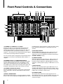
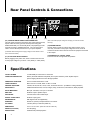
PSS-150
Portable Sound System
Owner’s Manual
Contents
Features
2
Warning
3
Installation
4
Inspection
4
Setup
4
FrontPanelControls&Connections
5
�earPanelControls&Connections
�ear Panel Controls & Connections
7
Specifications
7
Congratulations on your choice of a portable sound
system —youhavepurchasedoneofthefinestportable
soundsystemsonthemarkettoday.Thisunitwas
developedusingtheexpertiseofprofessionalsound
engineersandworkingmusicians.Youwillfindthatyour
newNADYAUDIOportablesoundsystemshassuperior
performanceandgreaterflexibilitythananyotherportable
soundsystemsinitspricerange.Pleasereadthismanual
carefullytogetthemostoutofyournewunit.
Thanks for selecting NADY AUDIO as your choice in
portable sound systems.
Features
•
•
•
•
•
•
•
•
•
ConvenientportablePApackagewithluggage-stylehandleandwheelsforeasytransport
5-Channelstereo150W�MSpoweredmixerAMA™(AutomaticMaximumAmplitude)limiterspeakerprotection
Stereotwo-wayspeakersystemwith10”wooferandpiezoelectrictweeterhorn,twospeakercables,andtwofoldingspeaker
stands
ThreecomboXL�/1/4”mic/lineinputsandoneXL�micinput,allwith15Vphantompower,andtwostereosourceinputsfor
CD,VC�,orDVDorotheraudiosources.Allinputswithbass,treble,andDSPEffectscontrols.
•Separatemasterleftandrightoutputcontrolswith60mmlinearfaders,1/4”speakeroutputs,and�CAauxiliarylinelevel
outputs
Five-bandgraphicequalizerwithFLI™(FeedbackLocatingIndicators)andchoiceof16digitaleffectsincluding�everb,Echo,
Delay,Phaser,Flanger,andChorus
DSPEffectsprocessorwithchoiceof16effectpresetsincludingHall/�oom/Plate�everbs,Chorus,Flanger,Delay,Vocal
Cancel,or�otarySpeaker
OneStarpower™dynamicmicrophoneand20footXL�microphonecable
Variable-speedfan
2
Warning
1.
Whenusingthiselectronicdevice,basicprecautionsshouldalwaysbetaken,includingthefollowing:
�eadallinstructionsbeforeusingtheproduct.
2. Donotusethisproductnearwater(e.g.,nearabathtub,washbowl,kitchensink,inawetbasement,ornearaswimmingpool,
etc.).
3. Thisproductshouldbeusedonlywithacartorstandthatwillkeepitlevelandstableandpreventwobbling.
4. Thisproduct,incombinationwithheadphonesorspeakers,maybecapableofproducingsoundlevelsthatcouldcause
permanenthearingloss.Donotoperateforalongperiodoftimeatahighvolumeleveloratalevelthatisuncomfortable.Ifyou
experienceanyhearinglossorringingintheears,youshouldconsultanaudiologist.
5. Theproductshouldbepositionedsothatproperventilationismaintained.
6. Theproductshouldbelocatedawayfromheatsourcessuchasradiators,heatvents,orotherdevices(includingamplifiers)that
produceheat.
7. Theproductshouldbeconnectedtoapowersupplyonlyofthetypedescribedintheoperatinginstructionsorasmarkedonthe
product.Replacethefuseonlywithoneofthespecifiedtype,size,andcorrectrating.
8. Thepowersupplycordshould:(1)beundamaged,(2)nevershareanoutletorextensioncordwithotherdevicessothatthe
outlet’sorextensioncord’spowerratingisexceeded,and(3)neverbeleftpluggedintotheoutletwhennotbeingusedforalong
periodoftime.
9. Careshouldbetakensothatobjectsdonotfallinto,andliquidsarenotspilledthrough,theenclosure’sopenings.
10. Theproductshouldbeservicedbyqualifiedservicepersonnelif:
a. Thepowersupplycordortheplughasbeendamaged.
b. Objectshavefalleninto,orliquidhasbeenspilledontotheproduct.
c. Theproducthasbeenexposedtorain.
d. Theproductdoesnotappeartooperatenormallyorexhibitsamarkedchangeinperformance.
e. Theproducthasbeendropped,ortheenclosuredamaged.
11. Donotattempttoservicetheproductbeyondwhatisdescribedintheusermaintenanceinstructions.Allotherservicingshouldbe
referredtoqualifiedservicepersonnel.
An equilateral triangle enclosing a lightning flash/arrowhead symbol
is intended to alert the user to the presence of uninsulated
“dangerous voltage” within the product’s enclosure which may be of
sufficient magnitude to constitute a risk of electric shock.
ATTeNTION: RISQUe De CHOC eLeCTRIQUe Ne PAS OUVRIR
An equilateral triangle enclosing an exclamation point is intended to
alert the user to the presence of important operating and service
instructions in the literature enclosed with this unit.
DateofPurchase
Dealer’sName
City
State
Model#
Serial#
3
Zip
Installation
To ensure years of enjoyment from your NADY AUDIO PSS150 Portable Sound System, please read and understand this
manual thoroughly before using the unit.
1. INSPeCTION
YourNADYAUDIOPSS-150PortableSoundSystemwas
carefullypackedatthefactoryinpackagingdesignedtoprotect
theunitsinshipment.Beforeinstallingandusingyourunit,
carefullyexaminethepackagingandallcontentsforanysignsof
physicaldamagethatmayhaveoccurredintransit.
[Please note: Nady Systems is not responsible for shipping
damage. If your unit is damaged, do not return to NADY, but
notify your dealer and the shipping company (if shipped to you)
immediately to make a claim. Such claims must be made by the
consignee in a timely manner.]
CONTeNTS:
•
PSS-150MixerSection
•
PSS-150LeftSpeaker
•
PSS-150�ightSpeaker
•
(2x)SpeakerStands
•
(2x)230’SpeakerCables
•
SP-1Starpower™Microphone
•
XC-2020’MicrophoneCable
•
ACcord
•
InstructionManual
•
WarrantyCard
2. SeTUP
AftertransportingthePSS-150tothedesiredlocation,laytheunit
downonitsflatside.Unclaspthesidepanellatchesbypulling
upontheyellowtabtoreleaseandunhookthelatch.Carefully
liftoffthespeakersandthenremovethespeakerstandsand
accessoriesfrominsidetheunit.
Mixer Section
PositionthePSS-150mixersectiononitsflatsurfacewiththe
controlpanelfacingup.Partsoftheunitcanbecomeverywarm
duringuse.Thisisnormalduringoperation.Careshouldbetaken
toensurethatthereisenoughspacebehindtheMixerSectionfor
cooling.Also,donotplacethePortableSoundSystemonhigh
temperaturedevicessuchaspoweramplifiers,etc.,ortheunit
mayoverheatinoperation.
europe (except UK): 230V, 50Hz
UK and Australia: 240V, 50Hz
USA and Canada: 120V, 60 Hz
Forotherareas,pleasecheckwithlocalauthorities.
Speakers and Stands
Fullyextendthespeakerstandtripodlegsandtightenthebase
thumbscrew.Extendthepoleofthestandtothedesiredheight
andinsertthesafetypincompletelythroughthestandholeabove
thepolethumbscrew.Lowerthepolesothatthepinrestsonthe
holderandtightenthepolethumbscrew.
Setupthestandsonaflatsurfacewherethespeakerswillbe
locatedandnotdisturbed.Placethespeakersonthestandsand
positionthemasdesired.Note:facingthespeakerstowardsany
ofthemicrophonesconnectedwiththePSS-150willincreasethe
chanceoffeedback.
Connectthespeakercablestotheinputjacksonthelowerleft
frontpanelofboththeLeftand�ightspeakers.Connecttheother
endofeachcabletothecorrespondingLeftand�ightspeaker
outputsontherearpanelofthePSS-150mixersection.Position
thelengthofthecablessotheywillnotbeasafetyhazardto
people.
WARNING:ConnectonlythesuppliedspeakerstothePSS-150.
NeverconnectadditionalspeakerstothePSS-150.
Inputs
Connectallsoundsourcestotheappropriateinputsi.e.,
microphones,keyboards,CDplayers,karaokemachines.
ThesuppliedSP-1Starpower™microphoneisanall-purpose
professionalstageandrecordingmicrophonewithruggedmetal
constructionandexcellentclear,transparentsoundacrossthe
spectrum.
Whenreadytooperate,plugtheACcordintothepowersource.
MakesurethattheunitisturnedoffbeforeconnectingtotheAC
powersourcetoavoidpossibleloudtransientswhichcandamage
yourspeakersoryourears.Beforeturningon,connectupthe
speakersandallinputsandoutputsdesiredandturndownthe
MasterVolume.
AlthoughthePSS-150isshieldedagainstradiofrequency(�F)
andelectromagneticinterference(EMI),extremelyhighfieldsof
�FandEMIshouldbeavoided.
Pleasemakesurethatthepowerunitsuppliedismarkedforthe
correctvoltageinyourarea(120VAC/60Hzor230VAC/50Hz).
Powerrequirementsforelectricalequipmentdifferfromareato
area.Innewinstallationsandportablesoundsystems,orany
situationinwhichtheACpowerisinquestion,itiswisetoconfirm
thevoltageandusetheappropriatepowersupplyunitbefore
connectingittopowersources.
4
Front Panel Controls & Connections
(1)
(2)
(3) (14)
(4)
(13)
(5)
(6)
(15)
(7)
(8)
(1) CHANNEL 1-3 COMBO XLR / 1/4’ INPUT
The XLR mic inputs are an electronically balanced XLR type
designed to accept mic level signals from any balanced or
unbalanced low impedance (Low Z) microphone. The XLR jacks
are configured for: Pin1 = ground, Pin2 = positive (+), Pin3 =
negative (-). The XLR jacks have 15VDC phantom power applied
to Pin2 and 3 for powering condenser microphones.
The 1/4” mono line inputs are designed to accept unbalanced line
level signals such as those from keyboards, drum machines, or
samplers.
(2) CHANNEL 4 XLR & 1/4” STEREO/MONO INPUTS
The XLR input is balanced, designed to accept mic level signals,
and has 15VDC phantom power. The Left and Right 1/4” line
inputs are for connecting stereo line level audio signals or only
the Left/Mono jack can be used for connecting mono signals. The
XLR input is defeated when either of the 1/4” inputs are used.
(3) CHANNEL 5 STEREO RCA INPUTS
The stereo RCA line level inputs can be used for connecting CD
players, Tape Decks, and other audio equipment with line level
outputs.
(4) MONO / STEREO MODE
When the Mono/Stereo button is out (stereo mode) the Left RCA
Aux In is sent to the Left Speaker and Right RCA Aux In is sent to
5
(9)
(10) (11)(12)
the Right Speaker. When the button is depressed (Stereo mode),
both L and R RCA input signals are mixed and sent to both
speakers.
(5) EFF SEND CONTROL
The EFF SEND control adjusts the level of signal sent by each
channel to the internal DSP (Digital Sound Processor). The
signal sent is mono, post-Treble/Bass and will be affected by the
CHANNEL FADER (8) setting.
(6) TREBLE CONTROL
Turn to the right to boost high frequencies, adding crispness too
percussion from drum machines, cymbals and synths. Turn to
the left to cut these frequencies, reducing sibilance or hiss. The
control has a shelving response giving +/-10dB of boost or cut at
10kHz.
(7) BASS CONTROL
The bass control shelving response gives 10dB of boost or cut
at 100Hz. Add warmth to vocals or extra punch to guitars, drums
and synths by turning to the right. Turn to the left to reduce stage
rumble, hum or to improve a mushy sound.
(8) CHANNEL FADER
The channel faders determine the output signal level to the
Master Mix bus. They offer a smooth logarithmic taper more often
associated with much more expensive consoles for optimum
control of the signal.
Front Panel Controls & Connections
(1)
(2)
(3) (14)
(4)
(13)
(5)
(6)
(15)
(7)
(8)
(9) DSP EFFECTS DISPLAY
This is displays the selected effect out of 16 possible effect
presets.
(10) DSP eFFeCTS SeLeCTOR
TheUP/DOWNbuttonsallowfastandeasyscrollingineither
directionthroughthe16effectpresets.
effects List:
0.�oom�everb1.5sec
1.Hall�everb2.8sec
2.LargeHall1.8sec
3.Echo7.0sec
4.Large�oom1.2sec
6.BrightHall3.0sec
7.Spring�everb2.0sec
8.Phaser
9.�ev/Flanger
A.�ev/Chorus
B.Hall/Chorus
C.Flanger
D.Ambient�everb
E.StereoDelay
F.Slapback�everb
(11) POWeR ON INDICATOR
ThisLEDlightsbluewhentheunitisON.
(12) 5-BAND GRAPHIC eQ
The5-bandchannelgraphicequalizerallowsyoutoadjustthe
(9)
(10) (11)(12)
frequencyresponseoftheLand�Channelbussignal,providing
amaximumof±12dBofcutandboostforeachfrequencyband
fromtheflatposition.Thefaderscanbeadjustedtoeasily
eliminatefeedbackfromthecorrespondingFLI™.
(13) FeeDBACK LOCATING INDICATORS (FLI™)
TheseLEDindicatorswilllightredwhenthereisahighlevel
audiosignalattheindicatedfrequency.Thesecanbeused
todetectanaudiofeedbackfrequencyandthenlowerthe
appropriateEQfadertoremovetheunwantedfeedback.
(Note: Observe care in selecting P.A. volume, microphone location and
speaker placement so that acoustic feedback (howling and screeching)
will be avoided. Please also observe the pickup patterns of the
microphone selected: omnidirectional mics pick up sound equally from all
directions and are prone to feedback if not used carefully. Unidirectional
mics are more resistant to feedback, but pick up sound sources best
that are directly in front of the mic. Also, mics that are farther from the
sound source require more acoustic gain and thus are also more prone to
feedback than close-source mics that are used close to the mouth.)
(14) AUX RCA OUTPUTS
TheLeftand�ight�CAoutputsprovidelinelevelsignaloutputto
acassettedeck,homeaudioequipment,orarecordingdevice.
(15) L/MONITOR and R/MAIN MASTeR FADeRS
Thesecontrolthefinallevelofthesignalsenttotheleftandright
SPeAKeR OUTPUTS (19)outputsandtheAUX RCA OUTPUTS
(14).ThesearealsonamedMonitorandMainforsituationswhen
theLeftspeakerwillbeusedasamonitorfortheperformersand
the�ightspeakerwillbepositionedtowardstheaudience.
6
Rear Panel Controls & Connections
(18)
(16)
(17)
(19)
(16) FUSe HOLDeR & POWeR CORD CONNeCTOR
ThisfuseholdercontainsanACprimaryfuse.Whenthisfuseblows,
replaceitwiththesametypefuse,sizeandpowerrating(see
SPECIFICATIONS).Ifitcontinuouslyblows,stopreplacingthefuse
andreferservicingtoqualifiedpersonnel.Thecordconnectoris
usedtoconnecttheACpowersourcetoyourpoweramplifier.
(CAUTION: After checking the AC supply voltage, be sure that the correct
fuse is in the fuse holder.)
(17) AC VOLTAGe SeLeCT SWITCH
Beforeplugginginthepowercord,checktoseethattheunitisset
forthepropervoltageforyourarea:~115V(60Hz)or~230V(50Hz).
(Note: use at the improper voltage can damage your unit and void the
warranty.)
(18) POWeR SWITCH
UsethisswitchtopowerunitONorOFF.Beforeturningonthis
unit,verifyconnectiontothepropervoltageACsource,checkall
connectionsandturndownthelevelcontrolsofequipmentconnected
totheoutputs.
(19) SPeAKeR 1/4” OUTPUT JACKS
ConnecttotheleftandrightPSS-150speakers.
Specifications
OUTPUT POWeR 75watts�MSperchannelinto4Ohmsload
OVeRLOAD PROTeCTION
AMA™(AutomaticMaximumAmplitude)servosystemlimitsthepoweramplifierinputto
preventclippingdistortionthatcandamagespeakers
FReQUeNCY ReSPONSe
40Hzto20KHzmeasuredat1watt
TONe CONTROLS
Bass:100Hz±+/-10dB;Treble:10KHz+/-10dB
GRAPHIC eQUALIZeR
5bands;100Hz,350Hz,1KHz,3KHz,and8KHzwithFLI™(FeedbackLocatingIndicators)
DSP eFFeCTS
Hall/�oom/Plate�everbs,Chorus,Flanger,Delay,VocalCancel,Chorus/�oom,�otarySpeaker
INPUT IMPeDANCe
Micinput:2KOhms,Lineinput:12KOhms
MAX GAIN
86dBmicinputtospeakeroutput
DISTORTION
Lessthan0.8%THDatratedoutput
SIGNAL / NOISe RATIO
85dBmicinputtypical
ReVeRB/DeLAY
DSPdigitalreverbanddigitaldelay
SPeAKeRS
Woofer10”(254mm)andpiezoelectrichorntweeter
AC POWeR
120VAC(60Hz)or230VAC(50/60Hz)
DIMeNSIONS
27.6”x15.75”x23.4”(70.2cmx40cmx59.4cm)
WeIGHT (assembled)
59.4lbs(27Kg)
MICROPHONe Unidirectional(cardioid)dynamic
7
Service For Your NADY AUDIO Product
(U.S.) ShouldyourNADYAUDIOproductrequireservice,pleasecontacttheNADYServiceDepartmentviatelephone
at(510) 652-2411,[email protected].
(International) Forservice,pleasecontacttheNADYAUDIOdistributorinyourcountrythroughthedealerfromwhom
youpurchasedthisproduct.
Do not attempt to service this unit yourself as it can be dangerous and will also void the warranty.
NADY SYSTeMS, INC.
6701ShellmoundStreet,
Emeryville,CA94608
Tel:510.652.2411/Fax:510.652.5075
www.nady.com