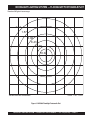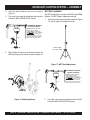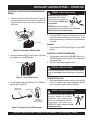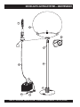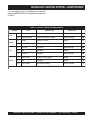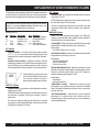
1
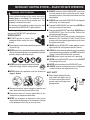
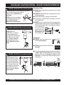
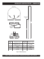
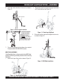
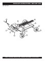
OPERATION & PARTS MANUAL Moonlight SERIES MODELS MB150 MB400 MB400B MB1000 MB1000W LIGHTING SYSTEM Revision #0 (10/27/06) To find the latest revision of this publication, visit our website at: www.multiquip.com THIS MANUAL MUST ACCOMPANY THE EQUIPMENT AT ALL TIMES. TABLE OF CONTENTS MOONLIGHT LIGHTING SYSTEM COMPONENT DRA WINGS DRAWINGS Table Of Contents ..................................................... 2 Parts Ordering Procedures ....................................... 3 Safety Message Alert Symbols ................................. 4 Rules For Safe Operation ...................................... 5-7 Dimensions ............................................................ 8-9 Specifications .......................................................... 10 Floodlight Footcandle Plots ............................... 11-12 General Information ................................................ 13 Components....................................................... 14-15 Assembly ............................................................ 16-19 Setup .................................................................. 20-22 Operation ................................................................ 23 Maintenance ...................................................... 24-25 Troubleshooting ...................................................... 26 Explanation Of Codes In Remarks Column ............ 28 Suggested Spare Parts ........................................... 29 Name Plate and Decals ..................................... 30-31 Balloon (with MBP) Assy. ................................... 32-33 Mast Assy. (MBC and MBS) ............................... 34-35 MBC Cart Assy. .................................................. 36-37 MBS Stand Assy. ................................................ 38-39 Terms and Conditions Of Sale — Parts .................. 40 NOTE Specification and part number are subject to change without notice. PAGE 2 — MOONLIGHT LIGHTING SYSTEM — OPERATION & PARTS MANUAL — REV. #0 (10/27/06) www.multiquip.com Effective: January 1st, 2006 PARTS ORDERING PROCEDURES Ordering parts has never been easier! Choose from three easy options: Best Deal! Order via Internet (Dealers Only): If you have an MQ Account, to obtain a Username and Password, E-mail us at: [email protected]. Order parts on-line using Multiquip’s SmartEquip website! ■ View Parts Diagrams ■ Order Parts ■ Print Specification Information To obtain an MQ Account, contact your District Sales Manager for more information. Use the internet and qualify for a 5% Discount on Standard orders for all orders which include complete part numbers.* Goto www.multiquip.com and click on Order Parts to log in and save! Note: Discounts Are Subject To Change Fax your order in and qualify for a 2% Discount on Standard orders for all orders which include complete part numbers.* Order via Fax (Dealers Only): All customers are welcome to order parts via Fax. Domestic (US) Customers dial: 1-800-6-PARTS-7 (800-672-7877) Note: Discounts Are Subject To Change Order via Phone: Domestic (US) Dealers Call: 1-800-427-1244 Non-Dealer Customers: Contact your local Multiquip Dealer for parts or call 800-427-1244 for help in locating a dealer near you. International Customers should contact their local Multiquip Representatives for Parts Ordering information. When ordering parts, please supply: ❒ ❒ ❒ ❒ ❒ ❒ Dealer Account Number Dealer Name and Address Shipping Address (if different than billing address) Return Fax Number Applicable Model Number Quantity, Part Number and Description of Each Part NOTE ❒ Specify Preferred Method of Shipment: ✓ UPS/Fed Ex ✓ DHL ■ Priority One ✓ Truck ■ Ground ■ Next Day ■ Second/Third Day All orders are treated as Standard Orders and will ship the same day if received prior to 3PM PST. WE ACCEPT ALL MAJOR CREDIT CARDS! MOONLIGHT LIGHTING SYSTEM — OPERATION & PARTS MANUAL — REV. #0 (10/27/06) — PAGE 3 MOONLIGHT LIGHTING SYSTEM — SAFETY MESSAGE ALERT SYMBOLS FOR YOUR SAFETY AND THE SAFETY OF OTHERS! Safety precautions should be followed at all times when operating this equipment. Failure to read and understand the Safety Messages and Operating Instructions could result in injury to yourself and others. NOTE This manual has been developed to provide complete instructions for the safe and efficient operation of the MQ MOONLIGHT Lighting System. Before using this Lighting System, ensure that the operating individual has read and understood all instructions in this manual. Potential hazards associated with the MOONLIGHT Lighting System operation will be referenced with Hazard Symbols which appear throughout this manual, and will be referenced in conjunction with Safety Message Alert Symbols. HAZARD SYMBOLS CAUTION - Rotating Parts NEVER operate equipment with covers, or guards removed. Keep fingers, hands, hair and clothing away from all moving parts to prevent injury. CAUTION - Sight and Hearing Hazards ALWAYS wear approved eye and hearing protection. SAFETY MESSAGE ALERT SYMBOLS The three (3) Safety Messages shown below will inform you about potential hazards that could injure you or others. The Safety Messages specifically address the level of exposure to the operator, and are preceded by one of three words: DANGER, WARNING, or CAUTION. CAUTION - Equipment Damage Messages Other important messages are provided throughout this manual to help prevent damage to your lighting system, other property, or the surrounding environment. DANGER You WILL be KILLED or SERIOUSLY injured if you DO NOT follow directions. NOTE WARNING You CAN be KILLED or SERIOUSLY injured if you DO NOT follow directions. This lighting system, other property, or the surrounding environment could be damaged if you do not follow instructions. CAUTION You CAN be INJURED if you DO NOT follow directions. PAGE 4 — MOONLIGHT LIGHTING SYSTEM — OPERATION & PARTS MANUAL — REV. #0 (10/27/06) MOONLIGHT LIGHTING SYSTEM — RULES FOR SAFE OPERATION WARNING - READ THIS MANUAL Failure to follow instructions in this manual may lead to Serious Injury or even Death. This equipment is to be operated by trained and qualified personnel only! This equipment is for industrial use only. ■ ALWAYS make sure that the MOONLIGHT is secure on firm level ground so that it cannot slide or shift around, endangering workers. Also keep the immediate area free of bystanders. ■ ALWAYS keep area behind MOONLIGHT clear of people while raising and lowering mast. The following safety guidelines should always be used when operating the MOONLIGHT Lighting System. ■ To prevent the MOONLIGHT from overturning, NEVER use in winds that exceed 22 mph(10m/s). The following safety guidelines should always be used when operating the MOONLIGHT Lighting System: ■ To prevent the MOONLIGHT from rolling, ALWAYS place the MOONLIGHT on a firm flat surface. Surface slant should not exceed 5 degrees. GENERAL SAFETY ■ DO NOT operate or service this equipment before reading this entire manual. ■ This equipment should not be operated by persons under 18 years of age. ■ NEVER operate this equipment without proper protective clothing, shatterproof glasses, steel-toed boots and other protective devices required by the job. ■ NEVER operate this equipment when not feeling well due to fatigue, illness or taking medicine. ■ NEVER operate this equipment under the influence of drugs or alcohol. ■ The MOONLIGHT should only be used in temperatures between 23°-104° Fahrenheit (-5° to 40° Celsius). Failure to comply with these operating parameters could cause the lamp to malfunction. ■ NEVER use the MOONLIGHT in rain, snow or areas of high humidity that could generate electrical storms. ■ CHECK the mast and winch cables for wear. If any problem occurs when lower or raising the mast STOP immediately! Contact a trained MQ technician for assistance. ■ NEVER pivot or retract mast while unit is operating. ■ NEVER use the MOONLIGHT mast as a crane. DO NOT lift anything with the mast. ■ NEVER attach anything to the MOONLIGHT mast. ■ ALWAYS lower the mast when not in use, or if high winds or electrical storms are expected in the area. MAST SAFETY ■ When raising or lowering the mast, keep hands and fingers clear of the various mast sections, this will prevent hands and fingers from getting pinched. ■ Whenever necessary, replace nameplate, operation and safety decals when they become difficult read. ■ Manufacturer does not assume responsibility for any accident due to equipment modifications. ■ NEVER use accessories or attachments, which are not recommended by Multiquip for this equipment. Damage to the equipment and/or injury to user may result. MOONLIGHT LIGHTING SYSTEM — OPERATION & PARTS MANUAL — REV. #0 (10/27/06) — PAGE 5 PINCH POINT MOONLIGHT LIGHTING SYSTEM — RULES FOR SAFE OPERATION LAMP SAFETY AND CARE TRANSPORTING ■ NEVER leave any grease or oil residue on lamp surface ■ When transporting the MOONLIGHT over rough terrain, when replacing or removing lamp. This can create hot remove the lamp and pack it safely so it will not be spots, reducing the service life of the lamp. damaged. ■ ALWAYS make sure the lamp surface is clean and dry. ■ ALWAYS replace with MQ recommended type lamp. See parts section of this manual. ■ NEVER use force when installing a lamp. Excessive force could cause the lamp to break causing bodily harm. ■ ALWAYS make sure the balloon support assembly is secure and the knob tightened. ■ NEVER attempt to replace lamp with the power on. Always unplug the power cord when changing the lamp. ■ NEVER unplug the lamp's AC power cable during operation. ■ ALWAYS allow a sufficient amount of time for the lamp to cool before changing. The possibility exists of severe burns. ■ ALWAYS have a trained technician install and remove lamp, or replace any damaged fixture wiring. DANGER - MOONLIGHT High Danger Areas The DANGER items listed below and on the next page are considered High DANGER areas and should be adhered to. Failing to understand these areas could result in Bodily Harm, Electrical Shock, Electrocution, and even Death! Please pay close attention when operating the MOONLIGHT. DANGER - Mounting Accessory Tipping ALWAYS make sure that the mounting pole, cart, stand or tripod is properly secured to prevent tipping! Use sandbags or stakes to secure the mounting accessory as necessary. ■ To prevent the balloon from deformation, NEVER use MOONLIGHT in strong winds. ■ DO NOT place the balloon inside storage case until the lamp has had a sufficient amount of time to cool down. ■ ALWAYS place the balloon inside its storage case after each use. This will prolong the life of the balloon material, keeping it protected from harsh environmental elements. ■ DO NOT use a damaged balloon. Replace balloon immediately if damaged. In addition, a damaged balloon will not inflate properly. ■ ALWAYS keep the balloon away from sharp objects and excessive amounts of heat (fire!). PAGE 6 — MOONLIGHT LIGHTING SYSTEM — OPERATION & PARTS MANUAL — REV. #0 (10/27/06) MOONLIGHT LIGHTING SYSTEM — RULES FOR SAFE OPERATION DANGER - MOONLIGHT Electric Shock Hazards ALWAYS keep electrical cords in good condition. Worn, bare or frayed wiring can cause electrical WET HANDS shock, thus causing Bodily Harm or even Death. NEVER grab or touch a live power cord with wet hands, the possibility exists of Electrical Shock, Electrocution, and even Death! POWER CORD (POWER ON) DANGER - MOONLIGHT Electric Shock Hazards DANGER - MOONLIGHT Electric Shock Hazards NEVER operate the MOONLIGHT or handle any electrical equipment while standing in water, while barefoot, while hands are wet, or in the rain. A dangerous electrical shock could occur causing Severe Bodily Harm or even Death. Maintenance Safety ■ NEVER lubricate components or attempt service on a running MOONLIGHT. ■ ALWAYS allow the MOONLIGHT a proper amount of time to cool before servicing. ■ Keep the MOONLIGHT in proper running condition. ■ Fix damage to the MOONLIGHT immediately and always replace broken parts. ■ ALWAYS use the required tool for the job application. Using damaged or worn tools or using tools inappropriate for the required application is very dangerous, and may cause damage to the machine and service personnel. Make sure to use the appropriate tool for the specific job. Emergencies ■ ALWAYS know the location of the nearest fire extinguisher. ■ ALWAYS know the location of the nearest first aid kit. DANGER - MOONLIGHT Overhead Obstructions ALWAYS make sure the area above MOONLIGHT is open and clear of overhead power lines and other obstructions. The tower extends in excess of 16 ft. (5 meters). Contact with overhead power lines or other obstructions could result in equipment damage, Serious Injury or Death! ■ In emergencies always know the location of the nearest phone or keep a phone on the job site. Also know the phone numbers of the nearest ambulance, doctor and fire department. This information will be invaluable in case of an emergency. MOONLIGHT LIGHTING SYSTEM — OPERATION & PARTS MANUAL — REV. #0 (10/27/06) — PAGE 7 MOONLIGHT LIGHTING SYSTEM — DIMENSIONS BALLOON MOUNTING POLE A E B C BALLOON SUPPORT BASE D F BASE G H Reference Letter Dimension in. (mm.) Reference Letter Dimension in. (mm.) A MB400B/MB100/W - 54 (1372) MB150 - 33.5 (851) E 118.5 (3010) B 25 (635) F 3.5 (89) C 11 (279) G 8 (203) D 67 (1702) H 21.5 (546) Figure 1. Balloon Dimensions PAGE 8 — MOONLIGHT LIGHTING SYSTEM — OPERATION & PARTS MANUAL — REV. #0 (10/27/06) MOONLIGHT LIGHTING SYSTEM — DIMENSIONS Reference Letter Dimension in. (mm.) Reference Letter Dimension in. (mm.) A 10.5 (267) D 12 (305) B 43 (1092) E 32 (813) C 8 (203) Figure 2. MBC Cart Dimensions MOONLIGHT LIGHTING SYSTEM — OPERATION & PARTS MANUAL — REV. #0 (10/27/06) — PAGE 9 MOONLIGHT LIGHTING SYSTEM — SPECIFICATIONS Table 1. Specifications Moonlight Model MB1000/MB1000W MB400/MB400B MB150 110 VAC 110 VAC 110 VAC 6 0 Hz 60 Hz 6 0 Hz 15 Amps 15 Amps 15 Amps Wind Stability (when base is secured) 55 mph (88.5 kph) 55 mph (88.5 kph) 55 mph (88.5 kph) Weight (without mount) 80 lbs. (36 kg) 66 lbs. (30 kg)/74 lbs. (33.5 kg) 49 lbs. (22 kg) 1000 Watt Metal Halide/ 1000 Watt Tungsten 400 Watt Metal Halide 150 Watt Metal Halide 110,000/21,500 42,000 15,000 Light Coverage (360°) 150 ft. (45.72 meters) 100 ft. (30.5 meters) 80 ft. (24.38 meters) Average Life 12,000 hours/variable 10,000 hours 10,000 hours 4500° K/3200° K 4500° K 4500° K Diameter 54 inches (1372 mm) 33.5 inches (851 mm)/ 54 inches (1372 mm) 33.5 inches (851 mm) Material Fire Retardant PVC Fire Retardant PVC Fire Retardant PVC Maximum Usage Temperature 158°/176°F (70°/80°C) 158°/176°F (70°/80°C) 158°/176°F (70°/80°C) Deformation Point 275°/320°F (135°/160°C) 275°/320°F (135°/160°C) 275°/320°F (135°/160°C) Water Resistance 100 % 100 % 100 % 67 in. (1702 mm) (with 67 in. telescope) 67 in. (1702 mm) (with 67 in. telescope) 67 in. (1702 mm) (with 67 in. telescope) 10 feet (3 meters) 10 feet (3 meters) 8 feet (2.4 meters) Input Voltage Frequency Max. Current Lamp Lamp Type Lumens Color Temperature Balloon MBP (option) Pole Maximum Height PAGE 10 — MOONLIGHT LIGHTING SYSTEM — OPERATION & PARTS MANUAL — REV. #0 (10/27/06) MOONLIGHT LIGHTING SYSTEM — FLOODLIGHT FOOTCANDLE PLOT Based on 360°glare-free coverage. 1.01 1.57 3.06 8.43 12.08 18.02 Scale: .5 IN. = 20 ft. Values listed as footcandles Figure 3. MB1000 Floodlight Footcandle Plot MOONLIGHT LIGHTING SYSTEM — OPERATION & PARTS MANUAL — REV. #0 (10/27/06) — PAGE 11 MOONLIGHT LIGHTING SYSTEM — FLOODLIGHT FOOTCANDLE PLOT Based on 360°glare-free coverage. .84 2.04 2.6 5.39 8.36 Scale: .5 IN. = 10 ft. Values listed as footcandles Figure 4. MB150 Floodlight Footcandle Plot PAGE 12 — MOONLIGHT LIGHTING SYSTEM — OPERATION & PARTS MANUAL — REV. #0 (10/27/06) MOONLIGHT LIGHTING SYSTEM — GENERAL INFORMATION The Multiquip MOONLIGHT Lighting System is a general purpose glare-free floodlight intended for applications such as security lighting, traffic control, freeway projects, jobsites, emergency lighting, indoor lighting, corporate functions and backyard parties. The Moonlight Lighting System provides illumination without the need to constantly inflate the balloon. The Moonlight Balloon comes in different models: 1000 Series - MB1000, MB1000W 400 Series - MB400, MB400B 150 Series - MB150 These models are shipped in a storage case that includes the following: Balloon Balloon Support Assembly Lamp Lamp System with Retainer Clip Ballast (Except MB1000W) Ballast Cable (Except MB1000W) Blower Blower Charger Cord DANGER - MOONLIGHT Overhead Obstructions ALWAYS make sure the area above MOONLIGHT is open and clear of overhead power lines and other obstructions. The tower extends in excess of 16 ft. (5 meters). Contact with overhead power lines or other obstructions could result in equipment damage, Serious Injury or Death! Bulbs The lighting system of Multiquip's MOONLIGHT (MB1000, MB400, MB400B, and MB150) is comprised of one "Metal Halide" lamp. This lamp has no filament (electric arc) therefore vibrations will not cause bulb failure. The bulbs can last up to 10,000 hours. The MB1000W is equipped with a Tungsten Carbide bulb. This bulb uses a filament and is not recommended for use in high vibration areas. For ease of service or transport, the lamp is equipped with a quick-disconnect connector that allows the lamp fixture to Mounting Accessories be removed quickly. This feature is extremely useful during Mounting Accessories are available from the MQ Sales transport of the MOONLIGHT over rough terrain. It is always department such as: best to remove the lamp and pack it safely so it will not be damaged. MBC - 4-Wheel Generator Cart MBS - 2-Wheel Transport Stand MBP - Mounting Pole MBT - Tripod (for MB150 and MB400 only) DANGER - Mounting Accessory Tipping ALWAYS make sure the mounting stand is properly secured to prevent tipping! Use sandbags or stakes to secure the mounting accessory as necessary. Balloons The balloon is made of airtight, fire-retardant, PVC-type material, and once it is inflated, can stay taut for months.The balloon can sustain at least 55 miles/hour winds. MOONLIGHT LIGHTING SYSTEM — OPERATION & PARTS MANUAL — REV. #0 (10/27/06) — PAGE 13 MOONLIGHT LIGHTING SYSTEM — COMPONENTS 18 1 17 2 3 5 4 6 7 16 8 15 12 14 10 13 9 11 Figure 5. Major Components (54-inch Balloon with Optional MBP) PAGE 14 — MOONLIGHT LIGHTING SYSTEM — OPERATION & PARTS MANUAL — REV. #0 (10/27/06) MOONLIGHT LIGHTING SYSTEM — COMPONENTS Figure 5 shows the location of the controls and components for the MOONLIGHT Lighting System. The function of each control is described below: 1. Balloon – This balloon is made of airtight PVC material with a diameter of 54 inches (MB400B, MB1000/W) or 33.5 inches (MB150). 2. Balloon Velcro Straps – Secures the balloon in place when attached to the support assembly (except 33.5inch models). 3. Balloon Support Assembly – Supports the balloon with the velcro straps in place (except 33.5-inch models). 4. Mounting Metal Rods – Used to hold balloon in the stand support adapter. Included with balloon support assembly on 54-inch models and included with balloon on 33.5-inch models. 5. Stand Support Adapter (with extrusion)– A pole that connects the balloon support assembly to the stand, to adjust the height of the balloon. 6. Adapter Bolt Lock – Secures the stand support adapter to the balloon support assembly when tightened. 7. Height Adjustment Knob – Adjusts the height of the pole (stand support adapter). When the pole is at the desired height, tighten lock to secure pole in place. 8. Stand – Supports the complete lighting system. NOTE 9. Wing Nut– Secures the stand into the base. Tighten screw to lock stand in place. 10. Metal Stand Base – Keeps the lighting system firmly set on the ground. 11. AC Power Cable – Connect this cable to a 120 VAC, 60 Hz power source. 12. ON/OFF Switch – Place this switch in the ON position to turn on the lamp. To turn off the lamp place in the OFF position. Please wait for approximately 10 minutes before attempting to turn the lamp back on. 13. Ballast – Provides the necessary electronics to light the lamp. 14. Blower – Used to inflate the balloon. 15. Ballast Cable – Connects the ballast to the lamp assembly. 16. Snap Ring – Ensures a complete seal of the balloon when the lamp is attached. 17. Lamp Assembly – Screw lamp into this assembly. If lamp becomes difficult to screw into assembly or assembly is damaged, replace assembly. 18. Lamp – 1000-watt, 400-watt, or 150-watt metal-halide type lamp. Replace only with MQ recommended type lamp. Always allow a sufficient amount of time for the lamp to cool down before changing. Items 5 to 10 are part of the MBP Mounting Pole. The Moonlight Balloon can also be mounted to the MBC 4-wheel Generator Cart, MBS 2-Wheel Transport Stand, or the MBT Tripod (MB150 and MB400 only). MOONLIGHT LIGHTING SYSTEM — OPERATION & PARTS MANUAL — REV. #0 (10/27/06) — PAGE 15 MOONLIGHT LIGHTING SYSTEM — ASSEMBLY MBC CART ASSEMBLY If the Moonlight balloon is to be mounted into the MBC Cart, perform the following assembly procedure before installing the balloon. 1. Step on the ON position of the brake on the wheel of the MBC cart to keep the cart in place during assembly. See Figure 6. T-HANDLE CLAMP STEP ON “ON” PEDAL TO ACTIVATE BRAKE. 4. Figure 6. Setting the Brake On 2. Figure 9. Clamped T-Handle Slide mast into the slot in the cart as shown in Figure 10. Tighten the 4 bolts to keep the mast in place. MAST Install the T-handle as shown in Figure 7 and tighten the bolt. SCREW TIGHTEN BOLTS (4 PLACES) T-HANDLE NUT 3. 5. Figure 7. T-Handle Installation Install the clamp as shown in Figure 8 and tighten with bolt. Push handle towards clamp to secure handle in place as shown in Figure 9. Figure 10. MBC Mast Installation Remove the pin near the top of the mast and insert the extrusion on the top of the mast. Reinsert the pin to hold extrusion in place. See Figure 11. EXTRUSION NUT PIN SCREW CLAMP Figure 8. Clamp Installation Figure 11. Extrusion Installation PAGE 16 — MOONLIGHT LIGHTING SYSTEM — OPERATION & PARTS MANUAL — REV. #0 (10/27/06) MOONLIGHT LIGHTING SYSTEM — ASSEMBLY 6. Install the winch handle on the mast as shown in Figure 12. 2. Step on the leg lock to release each leg and pull down until it locks in place (see Figure 14). WINCH HANDLE Figure 12. Winch Handle Installation DANGER! MAST GA-6HA TO PREVENT SERIOUS INJURY OR DEATH ALWAYS MAKE SURE AREA ABOVE MAST IS OPEN AND CLEAR OF OVERHEAD POWER LINES. THE POSSIBILITY EXISTS OF ELECTROCUTION, SHOCK, EVEN DEATH! IF THE BALLOON COMES IN CONTACT WITH HIGH VOLTAGE LINES. Figure 14. Stand Legs Deployed 3. Slide mast into the stand and and tighten the two nuts as shown in Figure 15. ON 0N V 120 OFF OFF 120 AC VOLTMETER IDLE CONTROL OFF OPERATION SWITCH 120V 120/240V 30A 120 120 30A 20A 21A AC CIRCUIT BREAKER 120V/240V 120V FULL POWER SWITCH 7. The cart is now ready for the balloon to be installed. Proceed to BALLOON INFLATION section. MBS STAND ASSEMBLY If the Moonlight balloon is to be mounted into the MBS Stand, perform the following assembly procedure before installing the balloon. 1. Attach the 4 legs of the stand as shown in Figure 13. Figure 15. MBS Mast Installation Figure 13. Stand Legs Installation MOONLIGHT LIGHTING SYSTEM — OPERATION & PARTS MANUAL — REV. #0 (10/27/06) — PAGE 17 MOONLIGHT LIGHTING SYSTEM — ASSEMBLY 4. 5. Install the winch handle on the mast as shown in MBT TRIPOD ASSEMBLY Figure 12. The MBT Tripod can be used with the MB150 and MB400 The stand is now ready for the balloon to be installed. Balloons. The MBT Tripod is shipped pre-installed. Proceed to BALLOON INFLATION section. 1. To secure the legs in place, loosen the knob (see Figure 17), pull the legs out and tighten the knob. TO PREVENT SERIOUS INJURY OR DEATH DANGER! MAST ALWAYS MAKE SURE AREA ABOVE MAST IS OPEN AND CLEAR OF OVERHEAD POWER LINES. THE POSSIBILITY EXISTS OF ELECTROCUTION, SHOCK, EVEN DEATH! IF THE BALLOON COMES IN CONTACT WITH HIGH VOLTAGE LINES. TWIST KNOB TO LOCK LEGS 6. When balloon and mast are removed and stored, the MBS stand legs can be stowed as shown in Figure 16. Figure 17. MBT Tripod Adjustments TO PREVENT SERIOUS INJURY OR DEATH DANGER! POLE Figure 16. Stand Legs Stored 2. ALWAYS MAKE SURE AREA ABOVE POLE IS OPEN AND CLEAR OF OVERHEAD POWER LINES. THE POSSIBILITY EXISTS OF ELECTROCUTION, SHOCK, EVEN DEATH! IF THE BALLOON COMES IN CONTACT WITH HIGH VOLTAGE LINES. The tripod is now ready for the balloon to be installed. Proceed to BALLOON INFLATION section. PAGE 18 — MOONLIGHT LIGHTING SYSTEM — OPERATION & PARTS MANUAL — REV. #0 (10/27/06) MOONLIGHT LIGHTING SYSTEM — ASSEMBLY MBP POLE ASSEMBLY If the Moonlight balloon is to be mounted into the MBP Pole, perform the following assembly procedure before installing the balloon. 1. Insert the pole (see Figure18) into the base and secure by tightening the wing nut on the base. Figure 18. MBP Mounting Pole Assembly 2. The pole is now ready for the balloon to be installed. Proceed to BALLOON INFLATION section. MOONLIGHT LIGHTING SYSTEM — OPERATION & PARTS MANUAL — REV. #0 (10/27/06) — PAGE 19 MOONLIGHT LIGHTING SYSTEM — SETUP 2. CAUTION - READ MANUAL Please read this entire manual carefully before attempting to operate the MOONLIGHT. Failure to read this manual could cause damage to the MOONLIGHT and serious injury to the operator. Unfold the PVC material of the balloon enough to allow the light fixture to be inserted into the balloon base. If necessary, use the supplied blower to help expand the PVC material as shown in Figure 21. NOTE The rechargeable blower is shipped with a minimal charge. Use AC adapter to charge before use. BALLOON COMPONENTS The various components of the balloon are contained in a case. Figure 19 shows all the different parts. BLOWER CHARGER CORD LAMP LAMP FIXTURE SNAP RING BALLOON SUPPORT BASE (EXCEPT MB150 AND MB400) Figure 21. Expanding the Balloon PVC Material BLOWER BALLAST (EXCEPT MB1000W) 3. BALLOON Install the lamp fixture into the balloon. Do not force the bulb against the PVC material as this may damage the bulb. Set the snap ring (Figure 22) into the o-ring groove to ensure a complete seal of the balloon. BALLAST CABLE Figure 19. Balloon Components BALLOON INFLATION 1. Screw the lamp into the lamp fixture as shown in Figure 20. Figure 22. Installing the Lamp Fixture 4. Unscrew the cap (Figure 23) on the lamp fixture and use blower to inflate balloon until it is taut. Screw the cap back on and tighten. Figure 20. Inserting the Lamp Figure 23. Inflating the Balloon PAGE 20 — MOONLIGHT LIGHTING SYSTEM — OPERATION & PARTS MANUAL — REV. #0 (10/27/06) MOONLIGHT LIGHTING SYSTEM — SETUP BALLOON INSTALLATION MB1000/MB1000W/MB400B (54-inch Balloons) 1. For MB1000/W and MB400B (54-inch balloons), insert the balloon support base metal rods into the extrusion on the mounting accessory (MBP, MBC, or MBS) and tighten the knobs to secure them in place. See Figure 24. BALLOON SUPPORT BASE KNOBS MB150/MB400 (33.5-inch Balloons) 1. For MB150 and MB400 (33.5-inch balloons), insert the balloon metal rods into the extrusion on the mounting accessory (MBP, MBC, MBS, or MBT) and tighten the knobs to secure them in place (see Figure 26). METAL RODS KNOBS EXTRUSION EXTRUSION Figure 24. Attaching the Support Baseto the Extrusion (MB1000/MB1000W/MB400B- 54-inch Balloons) 2. Figure 26. Attaching Balloon to the Extrusion (MB150/MB400 - 33.5-inch Balloons) Slowly invert the balloon and place over the installed balloon support base (Figure 25), making sure lamp fixture is facing down and the Velcro straps are aligned BALLOON DISASSEMBLY with the holes on the balloon support base. Insert Velcro 1. To disassemble unit, perform balloon inflation steps in strips into the holes and fasten securely. reverse order. Allow the lamp to cool for 15 minutes before attempting to disassemble unit. BALLOON VELCRO STRAP ( 6 PLACES) BALLOON SUPPORT BASE EXTRUSION Figure 25. Attaching Balloon to Support Base (MB1000/MB1000W/MB400B- 54-inch Balloons) MOONLIGHT LIGHTING SYSTEM — OPERATION & PARTS MANUAL — REV. #0 (10/27/06) — PAGE 21 MOONLIGHT LIGHTING SYSTEM — SETUP DANGER - Mounting Accessory Tipping ALWAYS make sure that the mounting pole, cart, stand or tripod is properly secured to prevent tipping! Use sandbags or stakes to secure the mounting accessory as necessary. MAST HEIGHT ADJUSTMENT (MBC and MBS) 1. To adjust the height of the mast on the MBC cart or MBS stand, rotate the winch handle until the mast is at the desired height (see Figure 28). ROTATE WINCH HANDLE Figure 28. MBC and MBS Mast Height Adjustment POLE HEIGHT ADJUSTMENT (MBP) 1. To adjust the height of the pole, loosen the height adjustment knob (see Figure 27) on the MBP mounting pole and slowly pull up the inner pole to the desired height. Tighten the height adjustment knob. CAUTION - Mast Safety When raising or lowering the mast, keep hands and fingers clear of the various mast sections, this will prevent hands and fingers from getting pinched. POLE HEIGHT ADJUSTMENT (MBT) 1. PULL OUT INNER POLE TO ADJUST HEIGHT KNOB Figure 27. MBP Pole Height Adjustment To adjust the height of the pole on the MBT tripod, remove the pin that holds the pole in place and loosen the knob (see Figure 29). Adjust the pole to the desired height and tighten knob to secure pole. Put back the pin to lock pole in place. REMOVE PIN TO RELEASE POLE LOOSEN KNOB TO ADJUST POLE HEIGHT CAUTION - Pole Safety When raising or lowering the pole, keep hands and fingers clear of the section between the pole and the inner pole. This will prevent hands and fingers from getting pinched. Figure 29. MBT Pole Height Adjustment PAGE 22 — MOONLIGHT LIGHTING SYSTEM — OPERATION & PARTS MANUAL — REV. #0 (10/27/06) MOONLIGHT LIGHTING SYSTEM — OPERATION ELECTRICAL CONNECTIONS (MB150/MB400/MB400B/ MB1000) 1. Insert the female end of the ballast cable (Figure 30) into the connector on the lamp fixture.Insert the male end of the ballast cable into the female connector on the ballast. DANGER - Electric Shock Hazards ALWAYS keep electrical cords in good condition. Worn, bare or frayed wiring can cause electrical shock, thus causing Bodily Harm or even Death. WET HANDS POWER CORD (POWER ON) NEVER grab or touch a live power cord with wet hands, the possibility exists of Electrical Shock, Electrocution, and even Death! BALLAST CABLE BALLAST Figure 30. Connecting the Ballast Cable 3. Place the ON/OFF switch to the ON position to turn on lamp. The lamp should flicker for a few minutes as the internal gases warm up. It should reach full power within 4 minutes. Shutdown 1. Place the power ON/OFF switch (Figure 31) in the OFF position. ELECTRICAL CONNECTIONS (MB1000W) 1. Make sure the power ON/OFF switch (Figure 31) located 1. Plug the power cable from the MB1000W directly to a on the ballast is in the OFF position. 110V/60 Hz power source (Figure 32). The lamp should automatically light. ON/OFF SWITCH 2. To turn off lamp, diconnect power cable. 1 0 CAUTION - LAMP COOL DOWN Allow a sufficient amount of time (15-20 minutes) for the lamp to cool down before attempting to disassemble unit. Figure 31. Power OFF/ON Switch 2. Plug the power cable from the ballast to a 110V/60 Hz power source (Figure 32). MOONLIGHT POWER CABLE RECEPTACLE MOVING THE BALLOON 1. When moving balloon around, make sure that the pole or mast is lowered to the shortest height possible and make sure pole or mast is securely fastened. DANGER - Overhead Obstructions EXTERNAL (110 VAC/60 Hz) POWER SOURCE Figure 32. Connecting to 110 VAC Receptacle When moving the Moonlight, ALWAYS be on the lookout for overhead obstructions such as high voltage power lines. The possibility exists of electrocution, even death if the MOONLIGHT comes in contact with high voltage power lines! MOONLIGHT LIGHTING SYSTEM — OPERATION & PARTS MANUAL — REV. #0 (10/27/06) — PAGE 23 MOONLIGHT LIGHTING SYSTEM — MAINTENANCE L1 B1 B2 P1 P2 L2 E3 P3 E2 E1 PAGE 24 — MOONLIGHT LIGHTING SYSTEM — OPERATION & PARTS MANUAL — REV. #0 (10/27/06) MOONLIGHT LIGHTING SYSTEM — MAINTENANCE For a prolonged life cycle an extended quality follow the recommended MOONLIGHT service guidelines as referenced in Table 3. TABLE 2. PERIODIC CHECK AND MAINTENANCE FIGURE PART CHECK ITEM SOLUTION L1 L a mp Defective lamp? Replace. ❖ L2 Cable/Connector Cable disconnected or loose? Connect securely. ■ B1 Balloon Defective or Worn? Replace. ❖ B2 Blower Not working properly? Repair or replace. ❖ P1 Bolt Lock Bolt loose? Tighten securely. ■ P2 Pole Damaged? Replace. ❖ P3 Wing Nut Nut loose? Tighten securely. ■ E1 Power Cable Defective or worn cable? Replace. ❖ E2 Plug Damaged? Replace. ❖ E3 On/Off Switch Not working properly? Repair or replace. ❖ Lamp Balloon Pole Electric ❖ - Daily Check ■ - Every 20 Hours MOONLIGHT LIGHTING SYSTEM — OPERATION & PARTS MANUAL — REV. #0 (10/27/06) — PAGE 25 MOONLIGHT LIGHTING SYSTEM — TROUBLESHOOTING Practically all breakdowns can be prevented by proper If the problem cannot be remedied, please leave the unit handling and maintenance inspections, but in the event of a just as it is and consult or company's service department. breakdown, please take a remedial action following the diagnosis based on the Troubleshooting (Table 3) information shown below. TABLE 3. TROUBLESHOOTING SYMPTOM Lamp does not light. POSSIBLE PROBLEM SOLUTION Is ballast cable securely connected? Plug in correctly. Are generator and light tower switched on? Turn on switch. Is lamp loose? Screw lamp securely into socket. Are any other electric appliances (other than light tower) plugged into power source? Unplug all other appliances. Is generator voltage normal (non-load voltage - 110 VAC)? Repair or replace generator. Is model of lamp compatible? Use genuine MQ lamp. Is lamp cool enough to light again? (Interval of 20 to 30 minutes is required before turning on lamp again) Wait for lamp to cool down. Is generator voltage normal (non-load Repair or replace generator. Lamp only lights for a voltage - 110 V)? shor t time. Is ambient temperature too high (more than Move lamp where there is proper 104 °F (40 °C)? ventilation. Balloon does not inflate. Is blower working properly? Check or recharge blower. Does balloon have a leak? Repair or replace balloon. PAGE 26 — MOONLIGHT LIGHTING SYSTEM — OPERATION & PARTS MANUAL — REV. #0 (10/27/06) NOTE PAGE MOONLIGHT LIGHTING SYSTEM — OPERATION & PARTS MANUAL — REV. #0 (10/27/06) — PAGE 27 EXPLANATION OF CODE IN REMARKS COLUMN The following section explains the different symbols and remarks used in the Parts section of this manual. Use the help numbers found on the back page of the manual if there are any questions. The contents and part numbers listed in the parts section are subject to change without notice. Multiquip does not guarantee the availability of the parts listed. Sample Parts List: NO. 1 2 2 3 4 REMARKS INCLUDES ITEMS W/ NOT SOLD SEPARATELY MQ-45T ONLY MAKE LOCALLY S/N 2345B AND ABOVE * A/R (As Required) is generally used for hoses or other parts that are sold in bulk and cut to length. A blank entry generally indicates that the item is not sold separately. Other entries will be clarified in the “Remarks” Column. Some of the most common notes found in the “Remarks” Column are listed below. Other additional notes needed to describe the item can also be shown. Assembly/Kit - All items on the parts list with the same unique symbol will be included when this item is purchased. Indicated by: NO. Column Unique Symbols - All items with same unique symbol ( , #, +, %, or >) in the number column belong to the same assembly or kit, which is indicated by a note in the “Remarks” column. * Duplicate Item Numbers - Duplicate numbers indicate multiple part numbers are in effect for the same general item, such as different size saw blade guards in use or a part that has been updated on newer versions of the same machine. NOTE Numbers Used - Item quantity can be indicated by a number, a blank entry, or A/R. REMARKS Column PART NO. PART NAME QTY. 12345 BOLT ....................... 1.... WASHER, 1/4 IN. ........... 12347 WASHER, 3/8 IN. .... 1.... 12348 HOSE .................... A/R .. 12349 BEARING ................ 1.... * * QTY. Column When ordering a part that has more than one item number listed, check the remarks column for help in determining the proper part to order. PART NO. Column Numbers Used - Part numbers can be indicated by a number, a blank entry, or TBD. TBD (To Be Determined) is generally used to show a part that has not been assigned a formal part number at time of publication. A blank entry generally indicates that the item is not sold separately or is not sold by Multiquip. Other entries will be clarified in the “Remarks” Column. “INCLUDES ITEMS W/(unique symbol)” Serial Number Break - Used to list an effective serial number range where a particular part is used. Indicated by: “S/N XXXXX AND BELOW” “S/N XXXX AND ABOVE” “S/N XXXX TO S/N XXX” Specific Model Number Use - Indicates that the part is used only with the specific model number or model number variant listed. It can also be used to show a part is NOT used on a specific model or model number variant. Indicated by: “XXXXX ONLY” “NOT USED ON XXXX” “Make/Obtain Locally” - Indicates that the part can be purchased at any hardware shop or made out of available items. Examples include battery cables, shims, and certain washers and nuts. “Not Sold Separately” - Indicates that an item cannot be purchased as a separate item and is either part of an assembly/kit that can be purchased, or is not available for sale through Multiquip. PAGE 28 — MOONLIGHT LIGHTING SYSTEM — OPERATION & PARTS MANUAL — REV. #0 (10/27/06) MOONLIGHT LIGHTING SYSTEM — SUGGESTED SPARE PARTS MOONLIGHT LIGHTING SYSTEM 1 TO 3 UNITS Qty. P/N Description Remarks 1 ......... 04568.......................... RING, SNAP ....................................................ALL MODELS 1 ......... 04569.......................... CAP, FILL .........................................................ALL MODELS 1 ......... 29903.......................... MOUNT, LIGHT ................................................ALL MODELS 1 ......... QS1869 ...................... PIN, SNAP 1/4” ................................................ALL MODELS 1 ......... MLHIT1000/U/LU/4K .. LAMP, 1000 W HID ...........................................MB1000 1 ......... MLHIT400/HBU/T15 ... LAMP, 400 W HID .............................................MB400 1 ......... MLHIT150 ................... LAMP, 150 W HID .............................................MB150 1 ......... 19850.......................... TIRE/RIM 410/350 X4 PNEUMATIC .................MBC, MBS 1 ......... 29920.......................... CASTER, 10" SWIVEL W/BRK ........................MBC MOONLIGHT LIGHTING SYSTEM — OPERATION & PARTS MANUAL — REV. #0 (10/27/06) — PAGE 29 MOONLIGHT LIGHTING SYSTEM — NAMEPLATE AND DECALS NAMEPLATE AND DECALS 1 2 PAGE 30 — MOONLIGHT LIGHTING SYSTEM — OPERATION & PARTS MANUAL — REV. #0 (10/27/06) MOONLIGHT LIGHTING SYSTEM — NAMEPLATE AND DECALS NAMEPLATE AND DECALS NO. PART NO. PART NAME 1 DCL1000 DECAL; WARNING LABEL, CORD-WRAP 2 DCL1010 DECAL; MOONLIGHT, POLE QTY. 1 1 REMARKS MOONLIGHT LIGHTING SYSTEM — OPERATION & PARTS MANUAL — REV. #0 (10/27/06) — PAGE 31 MOONLIGHT LIGHTING SYSTEM — BALLOON (WITH MBP) ASSY. BALLOON ASSY. 10 1 9 2 12 3 11 6 4 8 5 7 PAGE 32 — MOONLIGHT LIGHTING SYSTEM — OPERATION & PARTS MANUAL — REV. #0 (10/27/06) MOONLIGHT LIGHTING SYSTEM — BALLOON (WITH MBP) ASSY. BALLOON ASSY. NO. PART NO. 1 MLMLB54 1 MLMLB33 2 MLPC31 3 ML780322 4 ML780321 5 ML0015 6 MLCA15 7 MLBAL1000 7 MLBAL400 7 MLBAL150 8 MLC400 9 MLLK1000/400 9 MLLK150 10 MLHIT1000/U/LU/4K 10 MLHIT400/HBU/T15 10 MLHIT150 11 ML04568 12 ML04569 PART NAME QTY. REMARKS PVC BALLOON, 54" ........................................ 1 .......... MB1000, MB1000W, MB400B PVC BALLOON, 33.5" ..................................... 1 .......... MB400, MB150 PETG PLASTIC SUPPORT BASE ................. 1 .......... MLB54 INNER TELESCOPIC POLE 1 OUTER TELESCOPIC POLE 1 PLASMA CUT STEEL BASE 1 15-FT CONNECTOR CABLE 1 BALLAST, 1000 W / 110 V 1 BALLAST, 400 W / 110 V 1 BALLAST, 150W / 110 V 1 BLOWER (INFLATOR) 1 ELECTRICAL SYSTEM (LAMP) ..................... 1 .......... FOR 1000 AND 400 W LAMPS ELECTRICAL SYSTEM (LAMP) ..................... 1 .......... FOR 150 W LAMP LAMP, 1000 W HID 1 LAMP, 400 W HID 1 LAMP, 150 W HID 1 RING, SNAP 1 CAP, FILL 1 MOONLIGHT LIGHTING SYSTEM — OPERATION & PARTS MANUAL — REV. #0 (10/27/06) — PAGE 33 MOONLIGHT LIGHTING SYSTEM —MAST ASSY. (MBC and MBS) MAST ASSY. 16 3 1 9 7 12 8 14 12 2 5 2 4 11 17 6 8 4 15 18 10 13 PAGE 34 — MOONLIGHT LIGHTING SYSTEM — OPERATION & PARTS MANUAL — REV. #0 (10/27/06) MOONLIGHT LIGHTING SYSTEM — MAST ASSY. (MBC and MBS) MAST ASSY. NO. 1 2 3 4 5 6 7 8 9 10 11 12 13 14 15 16 17 18 PART NO. 0181 B 0730 1579 23793-001 4001 4196 5133 10024 29854 29891 29894 29902 29903 29910 29915 29916 29919 QS1869 PART NAME WASHER, LOCK 1/4” MED SCREW, HHC 1/4-20 X 1 SCREW, HHC 1/4-20 X .5 WHEEL-CONVEYOR CART, MASONRY SAW WASHER, FLAT USS 3/8 PLD SCREW, HHC 3/8-16 X .75 PIN CLEVIS 1/4 X 7/8” NUT, NYLOC 1/4-20 MAST W/A, LOWER MAST W/A, UPPER MAST W/A, MIDDLE GUIDE, MAST SLIDE MOUNT, LIGHT WINCH BRACKET, 1500 DL 5149646 CABLE, LOWER MAST, 1/8 X 96” CABLE, UPPER, MAST, 3/32 X 57” SWAGE, AL 3/32 X 57” PIN, SNAP 1/4” QTY. REMARKS 1 2 1 2 3 3 1 2 1 1 1 8 1 1 1 1 1 1 MOONLIGHT LIGHTING SYSTEM — OPERATION & PARTS MANUAL — REV. #0 (10/27/06) — PAGE 35 MOONLIGHT LIGHTING SYSTEM — MBC CART ASSY. MBC CART ASSY. 13 14 11 12 4 7 1 9 3 2 8 3 15 1 5 6 10 PAGE 36 — MOONLIGHT LIGHTING SYSTEM — OPERATION & PARTS MANUAL — REV. #0 (10/27/06) MOONLIGHT LIGHTING SYSTEM — MBC CART ASSY. MBC CART ASSY. NO. PART NO PART NAME 1 0205 SCREW, HHC 3/8-16 X 1.0 2 3615 COLLAR, SET 3/4 ID 3 4001 WASHER, FLAT USS 3/8 PLD 4 10019 NUT, NYLOC 10-32 5 10133 NUT, NYLOC 3/8-16 6 10176 NUT, NYLOC 1/2-13 7 19850 TIRE/RIM 410/350 X4 PNEUMATIC 8 29017 SCREW, HHC 1/2-13 X 5-1/2 9 29909 CLIP, 1" SPRING, GIBSON #225-L 10 29920 CASTER, 10" SWIVEL W/BRK 11 29927 CLAMP, MAST W/A, MBC 12 29928 CART BASE, W/A, MBC 13 29933 HANDLE W/A, MBC 14 29934 MAT, RUBBER V RIB, 5.5 X 29.75 15 5065B SCREW, PHP 10-32 X 1/2 QTY 12 2 12 1 8 1 2 1 1 2 1 1 1 2 1 REMARKS MOONLIGHT LIGHTING SYSTEM — OPERATION & PARTS MANUAL — REV. #0 (10/27/06) — PAGE 37 MOONLIGHT LIGHTING SYSTEM — MBS STAND ASSY. MBS STAND ASSY. 7 12 2 14 13 11 4 2 6 3 10 2 5 9 8 1 PAGE 38 — MOONLIGHT LIGHTING SYSTEM — OPERATION & PARTS MANUAL — REV. #0 (10/27/06) MOONLIGHT LIGHTING SYSTEM — MBS STAND ASSY. MBS STAND ASSY. NO PART NO 1 3615 2 4001 3 4196 4 10019 5 10133 6 10176 7 19716 8 19850 9 29905 10 29908 11 29909 12 29913 13 5065 B 14 06503-030 PART NAME COLLAR, SET 3/4 ID WASHER, FLAT USS 3/8 PLD SCERW, HHC 3/8-16 X.75 NUT, NYLOC 10-32 NUT, NYLOC 3/8-16 NUT, NYLOC 1/2-13 CRUTCH TIP TIRE, RIM 410/350 x4 PNEUMATIC BASE W/A RATCHET LOCK W/A CLIP, 1" SPRING, GIBSON #225-L SUPPORT LEG W/A SCREW, PHP 10-32 X 1/2 SCREW, HHC 1/2-13 X 3-3/4 QTY 2 14 2 4 4 4 4 2 1 4 4 4 4 4 REMARKS MOONLIGHT LIGHTING SYSTEM — OPERATION & PARTS MANUAL — REV. #0 (10/27/06) — PAGE 39 Effective: February 22, 2006 PAYMENT TERMS TERMS AND CONDITIONS OF SALE — PARTS 5. Parts must be in new and resalable condition, in the original Multiquip package (if any), and with Multiquip part numbers clearly marked. 6. The following items are not returnable: Terms of payment for parts are net 30 days. FREIGHT POLICY All parts orders will be shipped collect or prepaid with the charges added to the invoice. All shipments are F.O.B. point of origin. Multiquip’s responsibility ceases when a signed manifest has been obtained from the carrier, and any claim for shortage or damage must be settled between the consignee and the carrier. a. Obsolete parts. (If an item is in the price book and shows as being replaced by another item, it is obsolete.) b. Any parts with a limited shelf life (such as gaskets, seals, “O” rings, and other rubber parts) that were purchased more than six months prior to the return date. MINIMUM ORDER Multiquip reserves the right to quote and sell direct to Government agencies, and to Original Equipment Manufacturer accounts who use our products as integral parts of their own products. SPECIAL EXPEDITING SERVICE A $35.00 surcharge will be added to the invoice for special handling including bus shipments, insured parcel post or in cases where Multiquip must personally deliver the parts to the carrier. LIMITATIONS OF SELLER’S LIABILITY RETURNED GOODS POLICY d. Special order items. Return shipments will be accepted and credit will be allowed, subject to the following provisions: e. Electrical components. Multiquip shall not be liable hereunder for damages in excess of the purchase price of the item with respect to which damages are claimed, and in no event shall Multiquip be liable for loss of profit or good will or for any other special, consequential or incidental damages. f. Paint, chemicals, and lubricants. LIMITATION OFWARRANTIES g. Decals and paper products. 1. h. Items purchased in kits. No warranties, express or implied, are made in connection with the sale of parts or trade accessories nor as to any engine not manufactured by Multiquip. Such warranties made in connection with the sale of new, complete units are made exclusively by a statement of warranty packaged with such units, and Multiquip neither assumes nor authorizes any person to assume for it any other obligation or liability whatever in connection with the sale of its products. Apart from such written statement of warranty, there are no warranties, express, implied or statutory, which extend beyond the description of the products on the face hereof. The minimum charge for orders from Multiquip is $15.00 net. Customers will be asked for instructions regarding handling of orders not meeting this requirement. 2. A Returned Material Authorization must be approved by Multiquip prior to shipment. To obtain a Return Material Authorization, a list must be provided to Multiquip Parts Sales that defines item numbers, quantities, and descriptions of the items to be returned. a. The parts numbers and descriptions must match the current parts price list. b. The list must be typed or computer generated. c. The list must state the reason(s) for the return. d. The list must reference the sales order(s) or invoice(s) under which the items were originally purchased. e. The list must include the name and phone number of the person requesting the RMA. 3. A copy of the Return Material Authorization must accompany the return shipment. 4. Freight is at the sender’s expense. All parts must be returned freight prepaid to Multiquip’s designated receiving point. c. Any line item with an extended dealer net price of less than $5.00. 7. The sender will be notified of any material received that is not acceptable. 8. Such material will be held for five working days from notification, pending instructions. If a reply is not received within five days, the material will be returned to the sender at his expense. 9. Credit on returned parts will be issued at dealer net price at time of the original purchase, less a 15% restocking charge. 10. In cases where an item is accepted, for which the original purchase document can not be determined, the price will be based on the list price that was effective twelve months prior to the RMA date. 11. Credit issued will be applied to future purchases only. PRICING AND REBATES Prices are subject to change without prior notice. Price changes are effective on a specific date and all orders received on or after that date will be billed at the revised price. Rebates for price declines and added charges for price increases will not be made for stock on hand at the time of any price change. PAGE 40 — MOONLIGHT LIGHTING SYSTEM — OPERATION & PARTS MANUAL — REV. #0 (10/27/06) NOTE PAGE MOONLIGHT LIGHTING SYSTEM — OPERATION & PARTS MANUAL — REV. #0 (10/27/06) — PAGE 41 OPERATION & PARTS MANUAL HERE'S HOW TO GET HELP PLEASE HAVE THE MODEL AND SERIAL NUMBER ON-HAND WHEN CALLING UNITED STATES Multiquip Corporate Office 18910 Wilmington Ave. Tel. (800) 421-1244 Carson, CA 90746 Fax (800) 537-3927 Contact: [email protected] Mayco Parts 800-306-2926 Fax: 800-672-7877 310-537-3700 Fax: 310-637-3284 Service Department 800-421-1244 Fax: 310-537-4259 310-537-3700 MQ Parts Department 800-427-1244 310-537-3700 MEXICO UNITED KINGDOM MQ Cipsa Carr. Fed. Mexico-Puebla KM 126.5 Momoxpan, Cholula, Puebla 72760 Mexico Contact: [email protected] Tel: (52) 222-225-9900 Fax: (52) 222-285-0420 Fax: 800-672-7877 Fax: 310-637-3284 Warranty Department 800-421-1244, Ext. 279 Fax: 310-537-1173 310-537-3700, Ext. 279 Technical Assistance 800-478-1244 Fax: 310-631-5032 Multiquip (UK) Limited Head Office Hanover Mill, Fitzroy Street, Ashton-under-Lyne, Lancashire OL7 0TL Contact: [email protected] Tel: 0161 339 2223 Fax: 0161 339 3226 CANADA BRAZIL Multiquip 4110 Industriel Boul. Laval, Quebec, Canada H7L 6V3 Contact: [email protected] Multiquip Av. Evandro Lins e Silva, 840 - grupo 505 Tel: 011-55-21-3433-9055 Barra de Tijuca - Rio de Janeiro Fax: 011-55-21-3433-9055 Contact: [email protected], [email protected] Tel: (450) 625-2244 Fax: (450) 625-8664 © COPYRIGHT 2006, MULTIQUIP INC. Multiquip Inc., Mikasa, and the MQ logo are registered trademarks of Multiquip Inc. and may not be used, reproduced, or altered without written permission. All other trademarks are the property of their respective owners and used with permission. This manual MUST accompany the equipment at all times. This manual is considered a permanent part of the equipment and should remain with the unit if resold. The information and specifications included in this publication were in effect at the time of approval for printing. Illustrations are based on the Moonlight Lighting System. Illustrations, descriptions, references and technical data contained in this manual are for guidance only and may not be considered as binding. Multiquip Inc. reserves the right to discontinue or change specifications, design or the information published in this publication at any time without notice and without incurring any obligations. Your Local Dealer is: