1
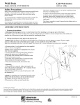
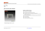
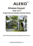
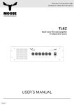
Bandwidth from dish to receiver
950 MHz to 1.45 GHz
Voltage range from receiver to dish
+10.5 VDC to + 21.0 VDC
LNB current range
50 mA to 200 mA*
Operating temperature range
-40º F to + 122º F
Dual pane window thickness range
0.50 to 0.75 inch
(For single pane glass, use Model 1111)
!
WARNING: To prevent electrical shock, do not attempt to
service unit. No user-serviceable parts inside.
* High current LNBs may require use of
model 1100 GlassLink™ Power Booster
Warranty
Glass
TM
dish-to-receiver connection
Model 1112
For Dual Pane Glass
(for single pane use model 1111)
Multiplex Technology, Inc., warrants this product to be free from defects in materials
and workmanship for a period of one year from the date of purchase or MTI will
repair or, at its option, replace the defective product. To obtain warranty service, call
MTI for a Return Material Authorization (RMA) number and return the product prepaid accompanied by a copy of the purchase receipt, to Multiplex Technology, Inc.,
3001 Enterprise St., Brea, CA 92821, Attn: Customer Service. Please put the RMA
number on the outside of the carton.
Any implied warranty arising from the sale of the product including implied
warranties of merchantability and fitness for purpose are limited to the warranty
stated above. MTI shall not be responsible for any loss, damages or expenses,
whether direct, consequential, or incidental arising from the use or inability to use
this product. Some states do not allow limitations on how long an implied warranty
lasts or the exclusion or limitation or incidental or consequential damages, so the
above limitations may not apply to you. This warranty gives you specific legal rights,
and you may have other rights which vary from state to state.
Note: This equipment has been tested and found to comply with the limits for a Class B digital device, pursuant to Parts 15 and
18 of the FCC Rules. These limits are designed to provide reasonable protection against harmful interference in a residential
installation. This equipment generates, uses and can radiate radio frequency energy and if not installed and used in accordance
with the instructions, may cause harmful interference to radio communications. However, there is no guarantee that interference
will not occur in a particular installation. If this equipment does cause harmful interference to radio or television reception, which
can be determined by turning the equipment off and on, the user is encouraged to try to correct the interference by one or more
of the following measures:
Reorient or relocate the receiving antenna.
Increase the separation between the equipment and receiver.
Connect the equipment to an outlet on a circuit different from that to which the receiver is connected.
Consult the dealer or an experienced radio/TV technician for help.
Glass
TM
INSID
E
Caution: Any changes or modifications not expressly approved by the manufacturer of this device could void the user's
authority to operate the equipment.
This device complies with part 15 of the FCC rules. Operation is subject to the following two conditions:
(1) This device may not cause harmful interference and
(2) This device must accept any interference received, including interference that may cause undesired operation.
multiplex ®
technology, inc.
3001 Enterprise St., Brea, CA 92821-6213. U.S.A.
714-996-4100 * 800-999-5225 * Fax 714-996-4900
Post-it™ is a trademark of 3M; GlassLink™ is a trademark of Multiplex Technology, Inc.
This product is covered by the following patents: US patent number 5612652, ROC patent number 086813
600-503 B
U.S. and international patents pending.
multiplex
®
technology, inc.
3001 Enterprise St., Brea, CA 92821-6213. U.S.A.
714-996-4100 * 800-999-5225 * Fax 714-996-4900
GlassLink™ Installation
GlassLink™ Installation
Part ONE: installation of OUTSIDE GlassLink™
Part TWO: installation of INSIDE GlassLink™
1. Using the instructions included with your satellite system, install the
dish and locate the satellite receiver in the house.
1. It is important that the INSIDE GlassLink™ be carefully aligned to
the OUTSIDE GlassLink™.
2. Identify a convenient window, through which the signals from the
dish can be routed to the receiver. Usually the GlassLink™ will be
located in a lower corner out of sight, but it can be located anywhere,
in any orientation, on the glass. Make sure the window uses dual
pane thermal glass, ½" to ¾" thick. Contact factory for pane
thickness outside this range.
2. From the inside, to eliminate a parallax view, look directly through the
glass at the OUTSIDE GlassLink™. Place the INSIDE GlassLink™
on the glass such that:
3. Clean the glass thoroughly with glass cleaner. Remove any stickers,
paint, decals, heat reflecting films, etc. from the surface of the glass
both inside and out. The glass must be perfectly clean and dry. If the
glass feels cold to the touch (less than 60º F), use a blow dryer to
warm the glass, evaporating any moisture that might be present.
4. Install the OUTSIDE GlassLink™ first. Remove the protective papers
from the face of the OUTSIDE GlassLink™ and press it firmly
against the glass. Push on all of the edges to make sure it is
seated uniformly all around.
5. Connect the cable from the dish to the OUTSIDE GlassLink™. Make
sure the cable is properly secured and does not "pull" on the
OUTSIDE GlassLink™.
6. From the inside, inspect the outside seal. Make sure that it is firm,
has no air bubbles, gaps or wrinkles. If there are, go back
outside and press until a good, even seal has been achieved.
Outside
TM
a. The notch of the INSIDE GlassLink™ corresponds to the
notch of the OUTSIDE GlassLink™.
b. The outline of the INSIDE GlassLink™ is aligned with
the outline of the OUTSIDE GlassLink™.
3. Once confident that you can repeat this location, remove the
protective paper and firmly press the unit into this position.
4. Now attach the cable from the satellite receiver to the INSIDE
GlassLink™. Make sure the cable is properly secured and does not
"pull" on the INSIDE GlassLink™.
5. Power up your satellite receiver. LED indicators should be visible on
the INSIDE GlassLink™. As you change channels on the satellite
receiver, you may notice that the LED indicators change color. If the
LEDs blink, or there are situations when both LEDs are
simultaneously lit, this may indicate the need for the GlassLink™
Power Booster. Call our technical support line at 1-800-999-5225 for
additional instructions.
Inside
OUTSIDE
GlassLink™
Glass
OUTSI
OUTSIDE
GlassLink™
INSIDE
GlassLink™
DE
INSIDE
TM
Glass
OUTSI
INSID
DE
OUTS
coax cable
from the dish
Glass
IDE
E
coax
cable
to the
receiver
TM
notch