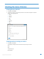
1
MultiConnect rCell Router Using the Router’s Web Interface Using the Router’s Web Interface 1 MultiConnect® rCell User’s Guide Intelligent Wireless Router S000573A, Revision A Copyright This publication may not be reproduced, in whole or in part, without prior expressed written permission from Multi‐Tech Systems, Inc. All rights reserved. Copyright © 2013 by Multi‐Tech Systems, Inc. Multi‐Tech Systems, Inc. makes no representation or warranties with respect to the contents hereof and specifically disclaims any implied warranties of merchantability or fitness for any particular purpose. Furthermore, Multi‐Tech Systems, Inc. reserves the right to revise this publication and to make changes from time to time in the content hereof without obligation of Multi‐Tech Systems, Inc., to notify any person or organization of such revisions or changes. Check Multi‐Tech’s Web site or product CD for current versions of our product documentation. Revisions Revision A Date Description 09/23/2013 Draft release. Trademarks Trademarks and registered trademarks of Multi‐Tech Systems, Inc. include MultiModem, the Multi‐Tech logo, and Multi‐Tech. Windows is a registered trademark of Microsoft Corporation in the United States and other countries. All other products or technologies referenced in this manual are the trademarks or registered trademarks of their respective holders. Contacting Multi‐Tech Support Online Support Portal: https://support.multitech.com To better serve our customers, manage support requests and shorten resolution times, we have created the online web portal allowing you to submit questions regarding Multi‐Tech products directly to our technical support team. Get answers to your most complex questions, ranging from implementation, troubleshooting, product configuration, firmware upgrades and much more. To create an account and submit a Support Case on the Portal, visit Knowledge Base and Support Services: https://support.multitech.com. www.multitech.com/support.go The Knowledge Base provides immediate answers to your questions and gives you access to support resolutions for all Multi‐Tech products. Visit our support area on the website for other support services. World Headquarters Multi‐Tech Systems, Inc. 2205 Woodale Drive, Mounds View, Minnesota 55112 USA Phone: 763‐785‐3500 or 800‐328‐9717 Fax: 763‐785‐9874 Internet Address: www.multitech.com Technical Support Business Hours: M‐F, 9am to 5pm CST Country By Email By Phone Europe, Middle East, Africa: [email protected] (44) 118 959 7774 U.S., Canada, all others: [email protected] (800) 972‐2439 or (763) 717‐5863 Warranty Warranty information can be found at: http://www.multitech.com/warranty.go Using the Router’s Web Interface 2 Table of Contents Welcome ........................................................................................................................................................................ 6 Getting started .......................................................................................................................................................... 6 Setting up your device ................................................................................................................................................... 7 Configuring miscellaneous features for your device ..................................................................................................... 9 Configuring IP address and DNS information for LANs ............................................................................................. 9 Configuring Dynamic Domain Naming System (DDNS) ........................................................................................... 10 Entering authentication information .............................................................................................................. 10 Forcing a DDNS server update ........................................................................................................................ 10 Configuring the DHCP server ................................................................................................................................... 11 Configuring a Dynamic Host Configuration Protocol (DHCP) Server .................................................................. 11 Assigning fixed addresses ................................................................................................................................... 12 Configuring GPS ....................................................................................................................................................... 12 Configuring the router for use with a Global Positioning System (GPS) ............................................................. 12 Notes: ......................................................................................................................................................... 13 Dumping NMEA sentence information to the router's TCP server port ......................................................... 13 Sending GPS information to a remote server ................................................................................................. 13 Configuring which NMEA sentences are sent and when they are sent .......................................................... 14 Configuring the serial port ...................................................................................................................................... 14 Configuring the serial port .................................................................................................................................. 14 Setting the device's date and time .......................................................................................................................... 15 Setting the date and time ................................................................................................................................... 15 Configuring SNTP to update date and time ........................................................................................................ 15 Configuring networks and services ......................................................................................................................... 15 Adding networks ................................................................................................................................................. 15 Adding networks............................................................................................................................................. 15 Editing or deleting an existing network .......................................................................................................... 16 Setting up wireless features ........................................................................................................................................ 17 Setting up Wi‐Fi access points ................................................................................................................................. 17 Setting security options ...................................................................................................................................... 18 Viewing information about Wi‐Fi clients using your wireless network .............................................................. 18 Setting up Wi‐Fi client ............................................................................................................................................. 19 Setting up bluetooth ............................................................................................................................................... 19 Setting up firewalls ...................................................................................................................................................... 22 Defining firewall rules ............................................................................................................................................. 22 Adding forwarding rules ..................................................................................................................................... 22 Adding Outbound Traffic Rules ........................................................................................................................... 22 Using the Router’s Web Interface 3 Advanced Settings .............................................................................................................................................. 23 Setting up static routes ........................................................................................................................................... 23 Setting up cellular features .......................................................................................................................................... 24 PPP configuration .................................................................................................................................................... 24 Configuring Point‐to‐Point (PPP) ........................................................................................................................ 24 Configuring PPP: Setting up the modem ............................................................................................................ 25 Configuring PPP: Setting up authentication ....................................................................................................... 25 Configuring PPP: Configuring keepalive checks .................................................................................................. 25 Configuring PPP: Sending modem commands to the integrated modem on router .............................................. 26 Configuring Modem AT Commands ............................................................................................................... 26 Example of Useful HSPA AT Commands: ........................................................................................................ 26 Example of Useful EV‐DO AT Commands: ...................................................................................................... 26 Setting up wake up on call ...................................................................................................................................... 26 Configuring wakeup‐on‐call ................................................................................................................................ 26 Example 1 – Determine if the router supports incoming calls and caller ID ...................................................... 27 Example 2 – Set Up the Ethernet Router to Activate on ALL Incoming Calls ...................................................... 27 Example 3 – Set Up the Ethernet Router to Activate on Matching Caller IDs Only: ........................................... 28 Example 4 – Set Up the Ethernet Router to Activate on Incoming SMS Message.............................................. 29 Setting up PPP ................................................................................................................................................ 29 Setting up Wake up on call ............................................................................................................................. 29 Setting up SMS ............................................................................................................................................... 29 Setting up Caller Acknowledgement .............................................................................................................. 30 Using Telnet to communicate with the cellular radio ............................................................................................. 30 Defining tunnels to your device ................................................................................................................................... 31 Setting up Generic Routing Encapsulation (GRE) tunnels ....................................................................................... 31 Defining Virtual Private Networks (VPNs) ............................................................................................................... 32 Administering devices.................................................................................................................................................. 33 Configuring how routers access the Internet .......................................................................................................... 33 Managing Your Device from Remote Server ........................................................................................................... 33 Setting up the Remote Server ............................................................................................................................. 33 Defining When the Device Connects to Remote Server ..................................................................................... 34 Defining When Device Gets or Sends Updates ................................................................................................... 34 Customizing the user interface ............................................................................................................................... 34 Customizing support information ....................................................................................................................... 34 Specifying Device Settings .................................................................................................................................. 35 Upgrading firmware ................................................................................................................................................ 35 Before you begin ................................................................................................................................................. 35 Using the Router’s Web Interface 4 Saving and restoring settings .................................................................................................................................. 36 Setting up the router's debug options .................................................................................................................... 37 Automatically rebooting the device ................................................................................................................... 37 Configuring Syslog ............................................................................................................................................... 37 Checking the status of devices .................................................................................................................................... 38 Viewing device statistics .......................................................................................................................................... 38 Viewing services running on routers ....................................................................................................................... 38 Using the Router’s Web Interface 5 Welcome This help file provides information on configuring, managing, and updating your MultiConnect® rCell 100 Series router. Your router includes a Web Management Interface (this application) that allows you to set up your router and the networks and devices that your router supports. You can use your rCell router to provide secure data communication between many types of devices that use legacy as well as the latest communication technologies. The router supports bluetooth and Wi‐Fi communication to devices with these technologies. The router has an integrated cellular modem and also includes 10/100BaseT Ethernet and RS‐232 serial connectivity. Getting started To access your router's web management interface: 1. Open an Internet browser. 2. In the browser's address field, type the default address for the router: http://192.168.2.1. A login page opens. 3. In the username field, type the default User Name: admin (all lower‐case). 4. In the password field, type the default password: admin (all lower‐case). 5. Click Login. The Web Management Home page opens. Using the Router’s Web Interface 6 Setting up your device The initial setup wizard can help you set up your device quickly with information that is commonly needed to operate the router. To use the wizard: 1. From Administration, select Initial Setup. A series of wizard panels step you through setup. 2. In the Choose Password panel, enter the following: 3. a. In the Current Password field, type the current password, that is, the password you want to change. The initial password shipped from the factory is admin. b. In the New Password field, type the password you want to use to replace the current one. c. To confirm the accuracy of the password, re‐type it in the Confirm Password field. d. Click Next. Or if you are done making changes, click Finish. In the Time Configuration panel, set the date time and time zone. 4. a. In the Time field, type the desired time. b. In the Date field, type the desired date. c. From the Time Zone drop‐down, select the time zone in which the router operates. d. Click Next. Or if you are done making changes, click Finish. In the IP Setup panel, give the router its address and network information: 5. a. In the IP Address field, type the router's IP address. b. In the Mask field, type the mask for the network. The default is 255.255.255.0. c. In the Primary DNS field, type the address of the primary DNS. . d. Click Next. Or if you are done making changes, click Finish. In the PPP Configuration panel, configure PPP for your router. Using the Router’s Web Interface 7 6. a. To use PPP, check Enable. When enabled, your device functions as a router. b. To enable the dial‐on‐demand feature, check Dial‐on‐Demand. To configure the settings that re‐ establish the connection when Dial‐on‐Demand is enabled, see Configuring wakeup‐on‐call. c. In the Idle Timeout field, type the amount of idle time that passes before the router times out. If the time expires, the PPP connection to the Internet is disconnected d. In the APN field, type the APN (Access Point Name). The APN is assigned by your wireless service provider. e. Click Next. Or if you are done making changes, click Finish. In the PPP Authentication panel: 7. a. From Type, select the authentication protocol type used to negotiate with the remote peer: pap, chap, or pap‐chap. The default is pap‐chap. b. In the Username field, type user name with which the remote peer authenticates. You can leave this field blank, if desired. Username is limited to 60 characters. c. In the Password field, type the password with which the remote peer will authenticate. You can leave this field blank, if desired. Password is limited to 60 characters. Click Finish. Using the Router’s Web Interface 8 Configuring miscellaneous features for your device Configuring IP address and DNS information for LANs Your router manages traffic for your local area networks (LANs). To change the IP address and DNS configuration: 1. From Setup, select IP Configuration. 2. To configure the address information: 3. In the IP Address field, type the router's IP address. The default is 192.168.2.1. In the Mask field, type the mask for the network. The default is 255.255.255.0. In the Gateway field, type the IP address of another gateway (router) that you want to use. In most router configurations, this field is not used. As such, the default is 0.0.0.0. To resolve names of hosts on the LAN into addresses, configure domain name server information (DNS). To allow the router to behave as a local DNS server, check Enable Forwarding Server. When a DNS request is received, the router forwards the request to a remote DNS server if there is no record in the router’s cache. New requests are cached in the router for future requests. In the Primary Server field, type the address of the primary DNS. The default is 0.0.0.0 In the Secondary Server field, type the address of the secondary DNS. The default is 0.0.0.0 The WAN DNS Servers field displays information about DNS servers, if any, that have been detected on the WAN link of the router. Using the Router’s Web Interface 9 Configuring Dynamic Domain Naming System (DDNS) This feature allows your router to use a DDNS service to associate a hosted server's domain name with a dynamically changing internet address. To configure your router to use DDNS: 1. From Setup, select DDNS Configuration. 2. In the Configuration group, check Enabled. 3. In the Server field, type the name of the server from which the currently assigned IP address is obtained. This check IP server is a server the router accesses to check its current IP address. 4. In the Port field, type the server's port number. Default is 80. 5. In the Max Retries field, type the maximum number of tries that are allowed if the update fails. The default is 5. The range is 0 to 100. 6. In the Update Interval field, type the days that pass with no IP Address change. At the end of this interval, the existing IP Address is updated on the server so that the address does not expire. The range of the interval you can enter is between 1 and 99 days. The default is 28 days. 7. If you want to query the server to determine the IP address before the DDNS update, check Use Check IP. The IP address is still assigned by the wireless provider and the DDNS is updated based on the address returned by Check IP Server. If disabled, the DDNS update uses the IP address from the PPP link. The default is Use Check IP. 8. In the Check IP Server field, type name to which the IP Address change is registered. Example: members.dyndns.org 9. In the Check IP Port field, type the port number of the Check IP Server. Default is 80. 10. From the System drop‐down list, select the desired system registration type, either Dynamic or Custom. The default is Dynamic. 11. In the Domain field, type the registered Domain name. Entering authentication information Your DDNS server requires you to identify yourself before you can make changes. To do so: 1. In the Username field, type the name that can access the DDNS Server. The default is NULL. You receive your name when you register with the DDNS service. 2. In the Password field, type the password that can access the DDNS Server. The default is NULL. You receive your password when you register with the DDNS service. Forcing a DDNS server update To update the DDNS server with your IP address, click Update. Using the Router’s Web Interface 10 Configuring the DHCP server Configuring a Dynamic Host Configuration Protocol (DHCP) Server You can configure your router to function as a DHCP server that supplies network configuration information— such as IP address, subnet mask, and broadcast address—to devices on the network. To configure the DHCP server: 1. From Setup, select DHCP Configuration. 2. To use the DHCP feature, check Enabled. 3. The Subnet field displays the subnet address. 4. The Mask field displays the network's subnet mask. 5. In the Gateway field, type the gateway address. The default Gateway address is the LAN IP address of the router. 6. In the Domain field, type your network domain, if any. 7. In the Lease Time field, type the DHCP lease time. Lease time is set in days, hours, and minutes. A Lease Time of 00‐00‐00 is an infinite lease time. 8. In the Lease Range Start field and in the Lease Range End field, type the range of IP addresses to be assigned by DHCP. 9. Click Submit. Using the Router’s Web Interface 11 Assigning fixed addresses You must let your router know about devices with fixed IP addresses. To do so, you manually enter the device's MAC address and the IP address that is bound to that MAC address. After you bind the MAC address to the IP address, the IP address cannot be used by any DHCP client with a different MAC address, even if there is no active DHCP connection with that IP address. To assign fixed addresses: 1. In the Fixed Address group, click Add. A dialog box opens, where you define the address. 2. In the MAC Address field, type the MAC address to which the specified IP address binds. 3. In the IP Address field, type the fixed IP address to be assigned. 4. Click Finish. The addresses are added. Configuring GPS Configuring the router for use with a Global Positioning System (GPS) Some routers have a built‐in GPS receiver. If your router has a GPS, the router can forward NMEA (National Marine Electronics Association) sentences from the GPS receiver to a device connected to the router's serial port. You can also send the GPS data over the network to a remote computer. To configure the GPS on your router: 1. From Setup, select GPS Configuration. The Setup:GPS configuration pane opens. 2. To configure the TCP server port and enable a serial port dump of NMEA sentences, see Dumping NMEA sentence information to the router's TCP server port. Using the Router’s Web Interface 12 3. To allow your router to connect and send GPS data to a remotely located server, see Sending GPS information to a remote server. 4. To set the time interval after which GPS data is sent, and to configure further details about the GPS information that is sent, see Configuring which NMEA sentences are sent and when they are sent. Notes: All enabled sentences are forwarded periodically using the interval specified in the NMEA Configuration section. Before forwarding, the router prepends an ID prefix and ID to each enabled NMEA sentence. The NMEA sentences available are those provided by the built in receiver which are: GPGGA, GPGSA, GPGSV, GPGLL, GPRMC, GPVTG. Detailed descriptions of the supported NMEA sentences are provided in the Universal IP AT Commands Reference Guide. You can simultaneously enable the TCP Server, TCP/UDP client and serial port dump. Dumping NMEA sentence information to the router's TCP server port To configure the TCP server port where you can send the NMEA sentences: 1. From the Local Configuration group, check TCP Server. 2. In the Port field, type the port number on which the TCP server is listening for connections. The default is 5445. You can use up to five digits. Each digit itself must be between 0 and 9. Numbers above 65,535 are illegal as the port identification fields are 16 bits long in the TCP header. 3. If you want the server to request that the remote client supply a password before the NMEA sentences are sent, type that password in the Password field. 4. To use the serial port for GPS, disable the serial port client/server. The serial port configuration settings are used to configure the port. The serial port client/server must be disabled to use the serial port for GPS. Sending GPS information to a remote server The Remote Configuration allows the device to connect to a remote server using the IP and port information for uploading GPS data. 1. To allow the device to connect, check TCP/UDP. 2. From the Protocol drop‐down list, select the protocol of the client. 3. In the Remote Host field, type the IP address of the remote host. 4. In the Port field type the port number of the remote host. 5. If your remote host requests a password, type that password in the Password field. The password is sent to the server in response. Using the Router’s Web Interface 13 Configuring which NMEA sentences are sent and when they are sent To configure the time interval, additional prefix or ID information, and which NMEA sentences that can be sent: 1. In the Interval field, type the amount of time, in seconds, that passes before the NMEA information is sent. The default is 10 seconds. The range is 1 to 255 seconds. 2. You can further identify the router—also called a remote asset—that is collecting and sending the GPS information. To do so: 3. Add ID The ID is an unique remote asset identification string. The ID string can be any length up to 20 characters, except that the & and $ are invalid characters. The ID must follow the standard NMEA sentence structure. Refer to the Universal IP AT Commands Reference Guide for sentence structure. To add more information to the beginning of the ID, in the Add ID Prefix field, type the information. You can select which NMEA sentence types you want to send. To do so, check the desired options: GCA, GSA, GSV, GLL, RMC, and VTG. Configuring the serial port Configuring the serial port To configure the serial terminal connected to the RS‐232 connector DE9 on the router: 1. From Setup, select Serial IP Configuration. 2. In the pane that appears, check Enabled. 3. From the Baud Rate drop‐down list, select the baud‐rate at which the serial terminal communicates. The default is 115200. 4. From the Flow Control drop‐down list, select the flow control for the serial port. The selections are None or RTS‐CTS. The default is None. 5. From the Parity drop‐down list, select the parity for the serial port. The selections are None, Even, or Odd. The default is None. 6. To use the Modbus protocol as the protocol the serial devices use to communicate, check Modbus. 7. From the Data Bits drop‐down list, select the data bits for the serial port. Data bit selection is 7 or 8. The default is 8. 8. From the Stop Bits drop‐down list, select the stop bits for the serial port. The selections are 1 or 2. The default is 1. Using the Router’s Web Interface 14 Setting the device's date and time You can configure how your router manages the setting of time on its domain of systems. The system date and time display in these formats: MM/DD/YYYY / HH:MM:SS You can set the date and time manually. Or you can configure the router to get this information from an SNTP server. Setting the date and time To set the router's date and time: 1. From Setup, select Time Configuration. The Setup: Time Configuration panel opens. 2. In the Date field, type in the date you desire, or select the date from the pop‐up calendar that opens 3. In the Time field, type the time. 4. From the Time Zone drop‐down list, select your time zone. The default selection is UTC (Universal Coordinated Time, Universal Time). To learn more about time zones, visit the following website: http://wwp.greenwichmeantime.com/info/current‐time.htm Configuring SNTP to update date and time To configure the server from which the SNTP date and time information is taken, and how often: 1. To enable SNTP to update the date and time, check Enabled. 2. In the Server field, type the SNTP server name or IP address that is contacted to update the time. 3. In the Polling Time field, type the time that passes, after which the SNTP client requests the server to update the time. Default is 120 minutes. You must enter time in minutes. Configuring networks and services Adding networks You can define, edit and delete networks that your router supports. These networks can later appear in your list of choices when configuring other items, such as tunnels. To setup networks: 1. From the Setup group, select Saved Networks. A list of networks already saved appears. 2. Add, edit or delete networks, as described in this topic. Adding networks To add a network: 1. Click Add Network. The Add Saved Network dialog box opens. 2. In the Name field, type the name of the network. 3. In the IP Address field, type the IP address of the network. Using the Router’s Web Interface 15 4. In the Subnet Mask field, type the network mask. Editing or deleting an existing network 1. To delete a network, click Delete. 2. At the top of the pane, a message tells you the network is deleted. To un‐do the delete, click the Undo link found in the message. 3. To edit a network, click Edit. Change the IP address or subnet mask as desired. Click Finish. Notes: You cannot edit the network name. You cannot delete a network if it is used in another configuration. Using the Router’s Web Interface 16 Setting up wireless features Setting up Wi‐Fi access points Your router can be configured as a wireless access point (AP) to allow Wi‐Fi enabled devices to connect to the router using Wi‐Fi. The Wi‐Fi hot spot can only handle 5 concurrent sessions. To set up your router so it can securely provide data communication to your Wi‐Fi devices: 1. From Wireless, select Wi‐Fi Access Point. 2. To allow the router to provide communication to Wi‐Fi devices, check Enabled. 3. To set the SSID (service set identifier) for the access point supported by your router, in the Network Name (SSID) field, type the name. This is the ID that Wi‐Fi devices look for in order to join the wireless network. All wireless devices on a WLAN must employ the same SSID in order to communicate with the access point. 4. To specify the data rates supported, in the Network Mode drop‐down list, select the desired option: B/G/N‐Mixed B/G‐Mixed B‐Only N‐Only 5. To specify the country where the network operates, in the Country Code field, type the Wi‐Fi code for the country. The country you choose has an impact on the channels over which the network can run. 6. To specify the channel on which the router operates, from the Channel drop‐down list, select the desired channel. United States uses channels 1‐11, Europe uses 1‐13, and Japan uses 14. 7. In the Beacon Interval field, type the period of time, in milliseconds, when the access point sends a beacon packet. Beacons help synchronize a wireless network. For most applications, the default value of 100 provides good performance. Using the Router’s Web Interface 17 8. In the DTIM Interval field, type how often a beacon frame includes a Delivery Traffic Indication Message, and this number is included in each beacon frame. It is generated within the periodic beacon at a frequency specified by the DTIM Interval. A delivery traffic indication message is a kind of traffic indication message (TIM) which informs the clients about the presence of buffered multicast/broadcast data on the access point. The default value of 1 provides good performance for most applications. You might want to increase this value when using battery powered Wi‐Fi devices, which can sleep (at reduced power consumption) during the longer DTIM interval period. You must balance the power savings from increasing the DTIM Interval against possible reduced communication throughput. 9. In the RTS Threshold field, type the frame size at which the AP transmissions must use the RTS/CTS protocol. This is often used to solve hidden node problems. Using a small value causes RTS packets to be sent more often, consuming more of the available bandwidth. However, the more RTS packets that are sent, the quicker the system can recover from interference or collisions. Setting security options You can specify the security protocol that the router uses to secure the communications from the router to the connected devices. 1. From the Mode drop‐down list, select the security protocol you want to use. Options include: None WEP: Use Wired Equivalent Privacy protocol to allow a group of devices on the network to exchange coded messages. WPA‐PSK: Use Wi‐Fi protected access to secure data exchanged on your network. WPA2‐PSK: Use Wi‐Fi protected access version 2 to secure data exchanged on your network. 2. To configure WEP: 3. a. From the Encryption drop‐down list, select the encryption to be used. b. To generate a key from a phrase, in the Passphrase field, type a phrase. Click Generate. c. To manually enter keys, type the keys in the Key 1, Key 2, Key 3 or Key 4 fields. To configure WPA‐PSK and WPA2‐PSK: a. Select the WPA Algorithm from the drop‐down list. b. In the Shared Key field, type the key that is used for encrypting and decrypting the data. c. To remove the mask characters, thereby making the Shared Key visible, check Unmask. When done, click Submit, then Save and Restart. Viewing information about Wi‐Fi clients using your wireless network To view information about clients (such as computers, tablets, and smart phones) that are using your router's Wi‐Fi features to exchange data: 1. The Clients group displays a list of clients using your router's WiFi. 2. To update the list, click Refresh. Using the Router’s Web Interface 18 Setting up Wi‐Fi client As an alternative to functioning as a Wi‐Fi Access Point, your router can function as a Wi‐Fi Client. 1. From Wireless, select Wi‐Fi Client. 2. To allow the router to act as a Wi‐Fi client, check Enabled. 3. From the Client Mode drop‐down list, select one of the following: WAN LAN 4. Click Submit. If Wi‐Fi Access Point feature is enabled, you are asked for permission to disable it before proceeding. 5. After 30 to 60 seconds, click Refresh. After a few seconds. a list of detected Wi‐Fi Access Points appears in the Available Networks group. 6. In the Available Networks group, click the SSID for the Wi‐Fi Access Point you want to use. The Add Saved Network dialog box opens. 7. Review the information, enter any required security info, then click Finish. The Wi‐Fi Access Point you just added appears in the Saved Networks group. 8. If desired, add additional Access Points to the list of Saved Networks. The router tries to connect to Saved Networks in the order they are listed. You can change the order by clicking the up or down arrows shown under options. 9. When done, click Submit, then Save and Restart. 10. The Status field displays "Connected" if you have successfully connected to the Wi‐Fi Access Point. Setting up bluetooth The Bluetooth‐IP feature allows a data connection between a remote TCP/UDP client or server and a local Bluetooth device. To set up the Bluetooth connection: 1. To enable the feature, check Enabled. Click Submit. Using the Router’s Web Interface 19 2. Confirm that the far‐end Bluetooth device is powered on and waiting for a connection. 3. In the Available Devices group, click Refresh. A list of detected Bluetooth devices appears. 4. Click the name of the Bluetooth device that you want to use. The name and MAC address appear under the selected device. To configure the IP Pipe in TCP/UDP Server mode: 1. In the IP Pipe group, from the Mode drop‐down list, select SERVER. 2. From the Protocol drop‐down list, select the desired protocol, either TCP or UDP. 3. In the Server Port field, type the desired port value in the range 1 to 65535. 4. From the Connection Termination drop‐down list, select a disconnect method for the IP pipe. Options are: Always Connected Sequence A sequence of characters received from the Bluetooth side used to disconnect the IP pipe. Timeout The IP pipe connection disconnects if the configured timer expires with no data sent or received. Using the Router’s Web Interface 20 To configure the IP Pipe in TCP/UDP Client mode: 1. In the IP Pipe group, from the Mode drop‐down list, select CLIENT. 2. From the Protocol drop‐down list, select the desired protocol, either TCP or UDP. 3. In the Server IP Address field, type the address of the far‐end TCP‐UDP server. 4. In the Server Port field, type the port value used by the far‐end TCP/UDP Server. 5. In case the primary server is unavailable, in the Secondary IP Address field and in the Secondary Port field, type the IP address and port number, respectively, of the alternate TCP/UDP server. 6. From the Connection Activation drop‐down list, select a connection method. Options are: 7. Always On CR Three carriage returns must be received from the Bluetooth side before TCP/UDP connection is established to the remote server. From the Connection Termination drop‐down list select a disconnect method for the IP pipe. Options are: Always Connected Sequence A sequence of characters received from the Bluetooth side used to disconnect the IP pipe Timeout The IP pipe connection disconnects if the configured timer expires with no data sent or received Click Submit. After you are finished configuring the Bluetooth feature, Save and Restart. The router immediately connects to the local bluetooth device. If successful the Status field displays Connected. If IP Pipe is configured for SERVER, the IP connection is initiated by the far‐end TCP/UDP client. If Mode is set to Client, the router initiates connections for the far‐end TCP/UDP server based on the configured Connection Activation conditions are met. Using the Router’s Web Interface 21 Setting up firewalls Defining firewall rules The router's firewall enforces a set of rules that determine how incoming and outgoing packets are handled. By default, all outbound traffic originating from the LAN is allowed to pass through the firewall, and all inbound traffic originating from external networks is dropped. This effectively creates a protective barrier between the LAN and all other networks. Adding forwarding rules For a device within the LAN to be visible from the internet or from an outside network, create a forwarding rule to allow incoming packets to reach the device. 1. In the Port Forwarding group, click Add Rule. 2. Enter a name and description. Click Next. 3. In the IP Forwarding DNAT pane, enter the following: 4. In the External WAN Ports field, type the port(s) to be forwarded. Common ports are listed in the field's attached drop‐down list and are exposed once you enter a character. Type ANY to forward all ports. In the Destination LAN IP field, type the IP address of the device packets will be forwarded to. The attached drop‐down list contains DHCP leased and Saved Network addresses. In the Destination LAN Ports field, type the port to which packets are translated. If there is a range of ports, the ending port is automatically set. The Destination LAN ending port is based on the Destination LAN starting port and the range provided in the External WAN Port(s) field. From the Protocol drop‐down list, select the protocol of the messages that can be forwarded. A default filter allowing forwarded packets through the firewall is automatically created. If desired you can use the Advanced Setting mode of the Port Forwarding wizard to further restrict packets based on source address and source ports. In most cases this is not necessary. Click Finish. Adding Outbound Traffic Rules To prevent a device within the LAN from communicating with a device in an external network, a rule has to be established in the firewall to drop packets destined to the external device. 1. Click Add Rule in the Outbound Traffic section. 2. Enter a name and description. Click Next. 3. In the Destination IP field, type the IP address of the device or network packets are being sent to. Type ANY if the destination address does not matter. 4. In the Destination Mask field, type the network mask of the destination network. 5. In the Destination Port field, type the port packets are destined for. Common destination ports are listed in the Destination Port field's attached drop down list. Type ANY if the destination port does not matter. 6. In the Source IP field, type the IP address of the device or network that the traffic originates from. Type ANY if the source address does not matter. 7. In the Source Mask field, type a network mask for the origin of the traffic. Using the Router’s Web Interface 22 8. In the Source Port field, type the port that is the origin of the traffic. Type ANY if the source port does not matter. 9. From the Action drop‐down list, select the action to perform on the traffic. You can allow the traffic to be accepted, rejected, logged or dropped. Accepted packets are allowed to continue through the firewall. Dropped packets are removed and no further processing is performed on them. Rejected packets are dropped, and an error message is sent to the source of the packet. Logged packets are logged to the system's main log file with the rule's name prepended as an identifier (viewable from the Statistics page). Log rules do not affect the packet's fate. 10. The Direction is locked to OUTGOING while using the Outbound Traffic wizard. 11. From the Protocol drop‐down list, select the protocol of the traffic that is being filtered. Advanced Settings The Firewall's Advanced Settings mode allows users to manipulate DNAT, SNAT, and Filter rules directly. DNAT rules can manipulate the destination address and port of a packet; similarly SNAT rules can manipulate the source address and port of a packet. Filter rules apply an ACCEPT, REJECT, DROP, or LOG action to a packet. DNAT, SNAT, and Filter rules can be associated if they are named the same. This association is recognized within the Port Forwarding and Outbound Traffic wizards accessed from the Normal Settings mode, and allows the associated rules to be viewed and edited as a series. Setting up static routes To set up a manually configured mapping of an IP address to a next‐hop destination for data packets: 1. From Firewall, select Static Routes. 2. In the pane that appears, click Add Route. 3. In the Name field, type the name of the route. 4. In the Address field, type the remote network IP address of the remote location. 5. In the Mask field, type the network mask that is assigned on the remote location. 6. In the Gateway field, type the IP address of the routing device that supports the remote IP Network. 7. Click Finish. Using the Router’s Web Interface 23 Setting up cellular features PPP configuration Configuring Point‐to‐Point (PPP) To configure how the PPP protocol is used on your router: 1. From Cellular, select PPP Configuration. 2. To use PPP, check Enabled. When enabled, your device functions as a router. If PPP is enabled, you cannot access the integrated cellular radio. 3. To access the cellular radio integrated with your router, disable PPP. When PPP is disabled, you can directly access the cellular modem by using telnet port 5000. 4. To enable the dial‐on‐demand feature, check Dial‐on‐Demand. To configure the settings that re‐ establish the connection when Dial‐on‐Demand is enabled, see Configuring wakeup‐on‐call. If disabled, the router always stays connected unless the Idle Time Out expires. 5. To allow the use of two antennas to increase receive signal quality, check Diversity. Note: Not all models support diversity. If you enable diversity, you must connect a second cellular antenna to the AUX port on the device. If you do not add the second antenna, and diversity is enabled, the device's performance can degrade. 6. In the Idle Time Out field, type the amount of idle time that passes before the router times out. The default is 180 seconds. If the time expires, the PPP connection to the Internet is disconnected. Any IP packets from the LAN side or IP traffic from the wireless side reset the timer and prevent disconnecting. 7. In the Connect Timeout field, type the number of seconds to wait for a connection while in receive mode before timing out. Using the Router’s Web Interface 24 8. In the Dialing Max Retries field, type the number of dialing retries allowed. The default is zero, which means an infinite number is allowed. The range is 0 to 100. Configuring PPP: Setting up the modem To set up the cellular modem that is integrated with your router: (Refer to the Customer Activation Notices included with the product for proper information to enter). 1. From Cellular, select PPP Configuration. 2. In the Dial Number field, type the number to be dialed. Default is NULL. For HSPA models, the Dial Number is *99***1# For EVDO models, the Dial Number is #777 For GSM models, the Dial Number is *99***1# For CDMA models, the Dial Number is #777 3. In the Connect String field, type the modem Connect String. The default is CONNECT. 4. In the Dial Prefix field, type the modem dial prefix. The default is ATDT. 5. In the APN field, type the APN (Access Point Name). The APN is assigned by your wireless service provider. 6. In the Init String1‐4 fields, type modem init strings. You can set up to 4 modem initialization strings. 7. In the PowerOn field, type the Power‐On Init String. You can enter a string of 0 to 40 characters that are sent to the router upon boot up. All commands initialize before you proceed with regular PPP related activity. When no initialization string is configured, regular functions of the router are retained. Configuring PPP: Setting up authentication To define authentication: 1. From the Authentication Type drop‐down list, select the authentication protocol type used to negotiate with the remote peer: pap, chap, or pap‐chap. The default is pap‐chap. 2. In the Username field, type user name with which the remote peer authenticates. You can leave this field blank, if desired. Username is limited to 60 characters. 3. In the Password field, type the password with which the remote peer will authenticate. You can leave this field blank, if desired. Password is limited to 60 characters. Configuring PPP: Configuring keepalive checks You can use the keep alive check feature to check the availability of the Internet connection. To configure the keep alive check: 1. Check Enabled. 2. From the Keep Alive Type drop‐down list, select the protocol type used for the check: ICMP or TCP. 3. In the Host Name field, type the name of the host computer used to respond to the keepalive. 4. In the TCP Port field type the TCP Port number to connect with the host. 5. In the Interval field, type the number of seconds that pass before a keepalive check is sent. Default is 60 seconds. Using the Router’s Web Interface 25 6. In the ICMP Count field, type the number of ICMP keepalive checks to be sent to the specified host. Default is 10. Configuring PPP: Sending modem commands to the integrated modem on router You can allow an external application to query modem information by setting up certain modem commands. The application can use the URL HTTP://xxx.xxx.xxx.xxx/modeminfor.html to get the IP address that is currently assigned to the integrated cellular modem after the PPP connection is established. This URL also shows the results of up to ten AT commands entered here. U U Configuring Modem AT Commands These commands are sent every time a PPP connection to the network is initiated. Example of Useful HSPA AT Commands: AT+CGSN Product Serial Number AT+CGMR Software Version AT+CSQ Signal Quality AT+CNUM Wireless Subscriber Number AT+COPS? Network Information (Operator) AT+CREG? Network Registration Example of Useful EV‐DO AT Commands: AT+CGSN Product Serial Number AT+CGMR Software Version AT+CSQ Signal Quality Setting up wake up on call Configuring wakeup‐on‐call The Wakeup‐on‐Call feature allows the router to wake up and initiate a connection when there is an incoming call or LAN activity. The Wakeup‐on‐Call feature can reduce costs when a router is online and available 24/7. To have some security surrounding this feature, you can set up the router to wake up based on receipt of a particular Caller ID or SMS instead of allowing all incoming calls to wake up the router. You must enable Dial‐on‐Demand for these settings to impact the router's operation. For more information about dial‐on‐demand, see Configuring general PPP features. To configure wakeup‐on‐call: 1. From Cellular, select Wake Up On Call. 2. In the pane that appears: Using the Router’s Web Interface 26 Configure wake‐up on call. Define the settings or events that occur in order to wake up the router. Example 1 – Determine if the router supports incoming calls and caller ID 1. From the Cellular option, select PPP Configuration. Make sure that PPP is disabled. 1. From the Cellular option, select Wakeup‐on‐Call. Make sure that Wakeup‐on‐Call is disabled. 2. Open a command prompt. To do so, on many Windows‐based operating systems, from the Start button select Run. 3. Type CMD to open the command window. Click OK. 4. When the command window opens, telnet to the router. 5000 is the router port number. 5. 6. a. To log in, type your username and password. b. Enter an AT command to make sure you receive a response, such as OK. c. To determine the dial number of the router, enter command AT+CNUM. From another phone, call your router using the number identified in step c. This lets you know if the RING message shows. To enable Caller ID, enter AT+CLIP=1 on the command window and make the call again to see if it shows Caller ID information. Notes: Step c must show the RING or CALLER ID information in order for the Wakeup‐on‐Call function to work. Some wireless providers might not provide caller ID information if you have only a data plan. Example 2 – Set Up the Ethernet Router to Activate on ALL Incoming Calls 1. From the Cellular option, select PPP Configuration. Set the following parameters: PPP General Make sure that PPP is Enabled. Make sure Dial‐on‐Demand is Enabled. Set the Idle Time Out to the number of seconds you desire. Authentication Your wireless service provider may require you to have a separate PPP user name and password.. If so, enter them here. If a user name and password are required, your wireless provider likely provided them to you when you activated your account. Modem Configuration Make sure your Dial Number is entered correctly: For HSPA models, the Dial Number is *99***1# For EV‐DO models, the Dial Number is #777 Click Submit 2. From the Cellular option, select Wake Up On Call. Set up the following parameters: Wakeup‐on‐Call Configuration Using the Router’s Web Interface 27 Check Wakeup‐on‐Call. Set the Time Delay to 3 seconds. You can use the 10 second default. Ensure that all Init Strings fields are empty. Submit Button Click Submit to save these settings. Caller ID Configuration 3. Enter the string RING to the Caller ID list. Click the Add Button to save the string to the Caller ID list. After you complete all your changes, save and restart. The device saves all the settings and reboots. Example 3 – Set Up the Ethernet Router to Activate on Matching Caller IDs Only: 1. From the Cellular option, select PPP Configuration. Set following parameters: PPP General Make sure that PPP is Enabled. Make sure Dial‐on‐Demand is Enabled. Set the Idle Time Out to the number of seconds you desire. Authentication Your wireless service provider may require you to have a separate PPP username and password. If so, enter them here. If a username and password are required, your wireless provider probably gave them to you when you activated your account. Modem Configuration Make sure your Dial Number is entered correctly: For HSPA models, the Dial Number is *99***1# For EV‐DO models, the Dial Number is #777 Submit • 2. Click Submit to save the changes. From the Cellular option, select Wakeup‐on‐Call. Set the following parameters: Wakeup‐on‐Call Configuration Check Wakeup‐on‐Call. Set the Time Delay. You can use the 10 second default. Enter the Init Strings: Set Wakeup Init String 1 by entering AT+CLIP=1 To save these settings, click Submit. Caller ID Configuration Enter a caller’s ID that you want added to the Caller ID list. Add Button Using the Router’s Web Interface 28 Click Add to save each Caller ID as it is entered to the Caller ID list. 3. After you complete all your changes, save and restart. The device saves all the settings and reboots Example 4 – Set Up the Ethernet Router to Activate on Incoming SMS Message Setting up PPP 1. From the Cellular option, select PPP Configuration. Set the following parameters: 2. In the PPP General section: Make sure that PPP is Disabled (the default). Make sure Dial‐on‐Demand is Disabled (the default). Set the Idle Time Out to the number of seconds you desire. 3. In the Authentication section, your wireless service provider may require you to have a separate PPP Username and Password. If so, enter them here. If username and password are required, your wireless provider likely gave them to you when you activated your account. 4. In the Modem Configuration section: Make sure your Dial Number is entered correctly: For GSM models, the Dial Number is *99***1# For CDMA models, the Dial Number is #777 Enter your APN. The APN is assigned by your wireless service provider. To save your changes click Submit. Setting up Wake up on call 1. From the Cellular option, select Wake Up On Call. 2. Check Enable. 3. Set the Time Delay. You can use 10 seconds as a default. 4. Enter the Init Strings so that the integrated cellular modem receives SMS. Enter Wakeup Init String 1 as AT+CMGF=1 Enter Wakeup Init String 2 as AT+CSMS=1 Enter Wakeup Init String 3 as AT+CNMI=2,2,0,0,1 Enter Wakeup Init String 4 as at^scfg=”URC/DstIfc”,mdm 5. To save these settings, click Submit. Setting up SMS 1. From the Cellular option, select Wake Up On Call. 2. In the On SMS group, check Enabled. 3. In the message field type an SMS. The SMS message string must not contain any spaces between words. When the configured string matches the SMS message string, it activates the Wakeup‐on‐Call feature 4. Click Add. Using the Router’s Web Interface 29 Setting up Caller Acknowledgement 1. In the group, in the field, type a configured string (0 to 40 characters) that is sent to the integrated cellular modem upon receiving a valid SMS from the WAN. 2. Set the Wakeup Acknowledgement string configuration with the command AT+CNMA. 3. To save the Acknowledgement Configuration click Submit. After you finish making your changes, you must save and restart. The device saves all the settings and reboots. Using Telnet to communicate with the cellular radio Your router comes with an integrated cellular radio. You can use this cellular radio directly without using any router functions. To do so, you must use redirector software on your computer. This software creates a virtual serial port that allows your computer to communicate with the integrated cellular radio over IP using telnet. To communicate directly with the cellular modem: 1. From Cellular, select Telnet Radio Access. 2. In the pane that appears, check Enabled. 3. To enable raw mode, check Raw. The program transfers data between the computer and cellular modem without any processing. 4. To enable the Auto Dialout Login feature, check Login. The Auto Dialout port is the Telnet port used by the redirector software on your computer to communicate to the cellular modem integrated on the router. 5. In the Port field, type the serial Auto Dialout Port number. The default is 5000. 6. In the Inactivity field, type the time in seconds that the auto dialout session remains active before becoming inactive. 7. To enable the EIA standard signal characteristics (time and duration) used between different electronic devices, check Handle EIA Signal. Using the Router’s Web Interface 30 Defining tunnels to your device Setting up Generic Routing Encapsulation (GRE) tunnels Tunneling allows the use of a public network to convey data on behalf of two remote private networks. It is also a way to transform data frames to allow them to pass networks with incompatible address spaces or even incompatible protocols. Generic Routing Encapsulation (GRE) is a tunneling mechanism that uses IP as the transport protocol and can be used for carrying many different passenger protocols. The tunnels behave as virtual point‐to‐point links that have two endpoints identified by the tunnel source and tunnel destination addresses at each endpoint. Configuring a GRE tunnel involves creating a tunnel interface, which is a logical interface, then configuring the tunnel endpoints for the tunnel interface. To set up GRE tunnels: 1. From Tunnels, select GRE Tunnels. The Tunnels: GRE Tunnels pane opens. 2. From the Tunnels:GRE Tunnels pane, click Add Tunnel. A series of wizard panels helps you configure the connection. 3. In the Tunnel Name field, enter a name for the new tunnel. 4. In the description area, type a description that helps you further identify the tunnel. Click Next. 5. In the next wizard pane: 6. In the Remote WAN IP field, type the IP address of the gateway to which you want to connect. (Optional) From the Saved Network drop‐down list, select the network that is to be routed through the tunnel. To select a local interface: Select the local interface on which the tunnel is being created. Eventually, the packets destined for this tunnel will be routed through it If you are not using a saved network, in the Network Route field, type the IP address of the network that is routed through the tunnel. If you are not using a saved network, in the Network Mask field, type the mask of the network. Click Add Route. The defined GRE tunnel configuration is added and appears in the Network Routes list. Click Finish. Using the Router’s Web Interface 31 Defining Virtual Private Networks (VPNs) Your router supports VPN tunnels for secure LAN‐to‐LAN access. To set up a VPN through your router: 1. From the navigation pane, select Tunnels, IPsec Tunnels. 2. In the pane that opens, click Add Tunnel. A series of wizard panels helps you configure the connection. 3. In the first panel, enter the following information: 4. 5. In the Name field, type a name for the connection. If desired, in the Description field, type a description for the connection. Click Next. In the next panel: In the Remote WAN IP field, type the IP address of the remote WAN. In the Saved Network drop‐down list, select the desired network. Otherwise you can manually define the network by completing the Network Route and Network Mask fields. Click Next. In the next panel: In the Pre‐Shared Key field type the pre‐shared key that is agreed upon and shared by the VPN endpoints. You must configure this key at both endpoints of the tunnel. From the Encryption Method drop‐down list, select the encryption method. 3DES is recommended. Options include 3DES, AES‐128, AES‐192, AES‐256. In the IKE Life Time field, type the duration for which the ISAKMP security association (SA) lasts, from successful negotiation to expiration. The default value is one hour and the maximum is 8 hours. In the Key Life field, type the duration for which the IPSec SA lasts, from successful negotiation to expiration. The default value is one hour and the maximum is 24 hours. In the Max Retries field, type the number of retries for the IPSec tunnel. Enter zero for unlimited retries. To enable the Local ID and Remote ID, check Enable UID (Unique Identifier String) . Then enter local ID and remote string identifiers: Local ID, type a string identifier for the local security gateway. Remote ID, type a string identifier for the remote security gateway. To enable IPCOMP, the compression algorithm, check Compression. To enable Perfect Forward Secrecy (PFS), a concept in which the newly generated keys are unrelated to the older keys, check Perfect Forward Secrecy. Click Finish. Using the Router’s Web Interface 32 Administering devices Configuring how routers access the Internet You must define how your router accesses the Internet and how the router can protect the networks and devices that it hosts. To set up the router for Internet access: 1. From the navigation pane, select Administration, Access Configuration. The Administration: Access Configuration pane opens. 2. To configure the web server, use the Web Server group. The topic Configuring the web server explains how to configure the web server. 3. To configure SSH, use the SSH group. The topic Configuring SSH explains how to configure SSH. 4. To configure ICMP, use the ICMP group. The topic Configuring ICMP explains how to configure ICMP. 5. To allow the router to defend against attacks, use the IP defense group. The topic Configuring IP defense explains how to configure IP defense in greater details. Managing Your Device from Remote Server Note: This feature is still being developed. As such, anticipate changes to how devices are remotely managed. This device can be configured to connect to a Remote Management Server. It can be managed and monitored through Multi Tech's Device Management Platform, including queueing software and configuration updates for the device. To configure the Remote Management feature: 1. From Administration, select Remote Management. 2. Set up the remote server. 3. To define when the device connects to the remote server, define connectivity options. 4. To define when the device gets or sends updates, define auto‐update settings. Setting up the Remote Server 1. To allow the device to connect to the Remote Management Server, check the "Enabled" box 2. If you want the device to use a secure connection, check SSL Enabled. This feature might be supported in a future release. 3. The Server Name field is pre‐populated with the address of the Remote Management Server. 4. The Server Port field is pre‐populated with the port the Remote Management Server listens on. You likely do not need to change this. 5. In the Account ID field type the account key received from the Multi Tech Remote Management Administrator. The device is not allowed to connect to the Remote Management Server without a valid account key. Using the Router’s Web Interface 33 Defining When the Device Connects to Remote Server 1. If you want the device to connect to the Remote Management Server only when the device's PPP link is up, check When PPP is up 2. If you want the device to bring up the PPP link when it is time for the device to connect to the Remote Management Server, check Bring up PPP. Defining When Device Gets or Sends Updates 1. To define how often the device connects to the Remote Management Server to request any pending updates, in the Query Server Interval field, type the desired value, between 0‐8640. 2. To define how often the device connects to the Remote Management Server to send GPS data, in the GPS Data Interval field type the desired value, between 0‐86400. 3. To define how often the device connects to the Remote Management Server to send network interface data, in the Network Stats Interval field, type the desired value, between 0‐86400. 4. To define how often the device connects to the Remote Management Server to send cellular data, in the Cellular Stats Interval field type the desired value, between 0‐86400. Customizing the user interface You can change how the user interface on your device appears. To change the interface: 1. From the Navigation pane, select Administration, Web UI Customization. 2. To define what information appears on the Administration: Support page, use the Support group. 3. To define other settings, use the Device Settings group. Customizing support information To customize the interface that displays information that can be used to support users: 1. To enable display of the custom support information, check Show Custom Info. 2. Type the desired information into the fields. For example, type the desired zip code in the Zip Code field, a city name in the City field, and so on. 3. To add a phone number: 4. Click Add Phone. A label can appear next to the phone number, for example "Fax" or "Phone" or "International". In the Label field, enter text that describes the phone number. In the Number field, type the phone number. To add a link to a website, click Add Link. To label the website, type label text in Label field. In the URL field, type the website's link. To add further descriptive text about the site, type the information in the Text field. Using the Router’s Web Interface 34 Specifying Device Settings To define other custom settings for devices: 1. In the Device Name field, type a name to identify the device. 2. In the Custom ID field, type an identifier for the device. 3. You can change the color of the interface's buttons, button fonts, highlights and highlight font by specifying red, green, and blue settings in their respective fields. Use the format #rrggbb to define the desired color in the respective field. 4. To add a favorite icon, also known as a shortcut icon or bookmark icon, in the Custom Fav Icon field, click Browse, navigate to the area where the file for the Fav icon resides, and select the desired file. 5. To add a custom logo, next to the Custom Logo field, click Browse. Navigate to the area where the logo resides, select the desired file. 6. Click Submit. Upgrading firmware Use this feature to upgrade the router’s firmware to the latest version. You can download firmware upgrades from the Multi‐Tech website. Before you begin Before you upgrade your firmware, save your present configuration as a backup. To upgrade the firmware on your device: 1. Go to the Multi‐Tech website, locate the firmware upgrade file you want for your router, and download this file to a known location. 2. From Administration, select Firmware Upgrade. The Administration: Firmware Upgrade pane opens. 3. In the Firmware Upgrade File field, point to the area where the upgrade file resides, and select the firmware file. To do so: 4. a. Click Browse. Navigate to the location of the file that is the firmware version you want to apply to your router. b. In this location select the file name and click Open. The file name appears in the Firmware Upgrade File field. Make sure you select the correct BIN file; otherwise, your router can become inoperable. Click Start Upgrade. 5. A message about time needed to upgrade appears. Click OK. A progress bar appears indicating the status of the upgrade. When upgrade is completed, your device reboots. Notes: The new firmware is written into flash memory It may take up to five minutes to upgrade the router's firmware. Do not interfere with the router's power or press the router's reset button during this time. Do not perform firmware upgrade remotely through the cellular wireless connection. After the firmware upgrade is complete, verify your configuration to make sure it is what you expected. Using the Router’s Web Interface 35 Saving and restoring settings To restore previous configuration settings to your router, to restore settings to their factory defaults or to save the current configuration: 1. From the navigation bar, select Administration, then Save/Restore. 2. To restore a previous configuration: 3. a. Next to the Restore Configuration field, click Browse. b. Navigate to the location where the configuration file is stored and select the desired file. c. Click Restore. The device reboots. To save a current configuration: 4. a. Click Save. b. A dialog box appears asking you if you want to open or save the configuration file. Click Save. c. In the dialog box that appears, navigate to the location where you want to store the configuration. Click Save. d. A progress dialog box appears to indicate that the configuration is being saved. Click Close. To restore the router's configuration to the factory default settings: a. Next to the Restore Factory Defaults field, click Restore. b. A dialog box appears, asking you to confirm that you want to restore factory default settings. c. Click OK. Using the Router’s Web Interface 36 Setting up the router's debug options You can set up your device to automatically reboot itself. You can also set up the device to record and report Syslog messages that can help you resolve issues you might experience with your device. To do so: From Administration, select Debug Options. Automatically rebooting the device To specify the amount of time that passes before the device automatically reboots itself: 1. In the Auto Reboot Timer field, type the number of hours that lapse before the device automatically reboots itself. The range you can enter is 0 to 999. 2. If you do NOT want the device to automatically reboot, set the time to 0. The default setting is 0. Configuring Syslog To enable and configure Syslog to capture and send messages from your device: 1. To activate Syslog, check Enabled. 2. To enable a remote server to receive and store the router's log data, in the IP Address field, type the IP address of the desired server. 3. To determine the amount of log information that is collected, in the Debug Log Level, type the value that represents the type of information you want to log. All messages with a priority level up to the given value are logged. For example, if you set the log level to 6 all messages with a priority from 0 through 6 are logged, and messages with a priority level of 7 are ignored. 4. To download Syslog information directly from the device, click Download. Using the Router’s Web Interface 37 Checking the status of devices Viewing device statistics 1. From Status, select Statistics. 2. The application categorizes statistics about your device. To see statistics that appear in a particular category, click the appropriate tab. System Ethernet Wireless PPP Serial Bluetooth GRE IPSec Viewing services running on routers 1. From Status, select Services. A panel appears, showing the status of services that may be running on the router: DDNS SNTP TCP/ICMP keep alive Dial on Demand Using the Router’s Web Interface 38