1
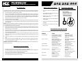
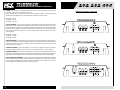
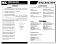
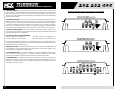
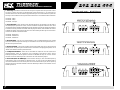
POWER
AMPLIFIER
OWNER’S
MANUAL
POWER AMPLIFIER OWNER’S MANUAL
ENGLISH
Introduction
CONGRATULATIONS...
HOW TO USE THIS MANUAL
on your purchase of a new MTX Audio
Thunder Amplifier! MTX has long been the
industry leader in mobile enclosures and
speakers, and we have reached new heights
with the development of the new MTX
Thunder amplifiers. You couldn’t have chosen
a more reliable, powerful, or better performing amplifier. In fact, we back up every
Thunder amplifier with a three-year warranty
if installed by an authorized MTX Audio retailer (see the warranty statement).
If you are installing this amplifier yourself, we recommend that you read the manual cover-to-cover
before you install it. Familiarize yourself with the features and details on the input and output panels.
Make sure you have all the equipment you need.
Then follow the step-by-step installation instructions
included. Sample installation diagrams may be found
on our website:
Your new MTX Thunder amplifier was
designed, built and thoroughly tested at our
state-of-the-art electronics manufacturing
facility. We manufacture every amplifier using the
latest Intelligent Surface Mount Technology. Some
of the advantages of the new design are its significant improvements to the amplifier’s electrical and
mechanical properties. ISMT devices feature substantially shorter internal and external lead lengths.
This reduces stray capacitance and inductance,
which results in cleaner and more accurate musical
reproduction with significantly less noise interference. The ISMT mounter produces amplifier boards
with smaller and lighter components, which are
more resistant to vibrations inherent in the automotive environment.
A word about power ratings. It is important for you to
know how they stack up. MTX has chosen the most
honest, most conservative way to rate our amps. We
show you the RMS power, at 12.5 volts, and dynamic
power at 14.4 volts. However, we go above and
beyond the call of duty. We test each amplifier. The
technician records the “actual” power output, and
records this number on your Certified Performance
Certificate. The amplifier must meet or exceed the
rated specification before we’ll ship it. No questions.
No exceptions.
We want to ensure you get continuous high performance from your MTX Thunder amplifier, so we recommend that you have it professionally installed by
your authorized MTX dealer.
2
Features
mtx.com
If you have any questions, write or call us:
• Thunder Amplifiers are Covered by One or More
of the Following United States of America
Patents: #5,598,325, #5,631,608, #5,783,970
• Acoustically Seamless Turn-On/Turn-Off
• Adjustable Input Sensitivity
• Anti-Shock PCB Mounting Design
• High Powered Transformer
• Intelligent Surface Mount Technology
• Nickel-Plated, Heavy Duty Terminal
Block Connectors
• Patented PWM MOSFET Switching Power Supply
• Real Time Computerized Protection Circuit
• Unique Rubber Insulated Iso-Feet™
• 18dB/Octave Crossover
MTX Audio
4545 E. Baseline Rd. Phoenix, AZ 85042
602-438-4545 • 800-CALL MTX
[email protected]
mtx.com
Please take a moment to register your purchase
on-line at mtx.com.
Please also record the serial number of your
amplifier in the space provided below and keep this
manual for future reference, as well as your sales
receipt as proof of ownership. (The serial number
of your amplifier is marked on the bottom of its
metal chassis.)
SERIAL NUMBER:
DATE OF PURCHASE:
• Bridgeable Circuit Design
• Buffered RCA Output for Daisy-Chaining
Multiple Amplifier
• Color-Coded Wire Harness for Speaker-Level
Input Installation
• Patented Class A 100% Discrete Driver
Circuit Topology
• Patented Pure N-Channel Design
• Smart-Engage™ Auto Turn-On for Easy
Integration with Factory Head Units When
Using Speaker Level Inputs
• Speaker and Low Level Inputs
• Input Select Switch Functions as a Built-In Y
Connector (THUNDER404)
Specifications
THUNDER202
THUNDER404
• RMS Power measured at 12.5 Volts DC:
35 Watts x 2 into a 4 Ohm load with less than 1%THD
70 Watts x 2 into a 2 Ohm load with less than 1%THD
140 Watts bridged into a 4 Ohm load with less than 1%THD
• Dynamic Power measured at 14.4 Volts DC:
50 Watts x 2 into a 4 Ohm load
100 Watts x 2 into a 2 Ohm load
200 Watts bridged into a 4 Ohm load
• Signal to Noise Ratio: ≥100dB A-Weighted
• Damping Factor: >200
• Frequency Response: 20Hz-20kHz ± 0.25dB
• Maximum Input: 2.5Vrms
• Crossover: 18dB/Octave, 85 Hz, High Pass, Low Pass,
or Full Range
• Dimensions: 8" x 9.75" x 2.1" (20.4cm x 24.8cm x 5.3cm)
• RMS Power measured at 12.5 Volts DC:
35 Watts x 4 into a 4 Ohm load with less than 1%THD
70 Watts x 4 into a 2 Ohm load with less than 1%THD
140 Watts x 2 bridged into a 4 Ohm load w/less than 1%THD
• Dynamic Power measured at 14.4 Volts DC:
50 Watts x 4 into a 4 Ohm load
100 Watts x 4 into a 2 Ohm load
200 Watts x 2 bridged into a 4 Ohm load
• Signal to Noise Ratio: ≥100dB A-Weighted
• Damping Factor: >200
• Frequency Response: 20Hz-20kHz ± 0.25dB
• Maximum Input: 2.5Vrms
• Crossover: 18dB/Octave, 85 Hz, (Front) High Pass or Full
Range, (Rear) High Pass, Low Pass, or Full Range
• Dimensions: 11.5" x 9.75" x 2.1" (29.3cm x 24.8cm x 5.3cm)
THUNDER282
• RMS Power measured at 12.5 Volts DC:
45 Watts x 2 into a 4 Ohm load with less than 1%THD
90 Watts x 2 into a 2 Ohm load with less than 1%THD
180 Watts bridged into a 4 Ohm load with less than 1%THD
• Dynamic Power measured at 14.4 Volts DC:
70 Watts x 2 into a 4 Ohm load
140 Watts x 2 into a 2 Ohm load
280 Watts bridged into a 4 Ohm load
• Signal to Noise Ratio: ≥100dB A-Weighted
• Damping Factor: >200
• Frequency Response: 20Hz-20kHz ± 0.25dB
• Maximum Input: 3Vrms
• Crossover: 18dB/Octave, 85 Hz, High Pass, Low Pass,
or Full Range
• Dimensions: 9.4" x 9.75" x 2.1" (23.9cm x 24.8cm x 5.3cm)
3
POWER AMPLIFIER OWNER’S MANUAL
Installation
Any deviation from the connection specifications recommended may cause serious damage to the amplifier,
speakers and/or vehicle electrical system. Please double-check the connection before turning the system on.
1. Disconnect the vehicle’s negative battery connection.
2. Place your Thunder amplifier at the predetermined mounting location. Using a felt pen, mark the exact
position of the mounting holes on the mounting surface. Set the amplifier aside. Use a sharp, precise blade
to cut small circles in the carpet and padding around the four marks denoting your mounting holes to
expose the metal underneath. Use a center punch to make an indentation in the metal to ensure that you
drill the exact position for the screws. Drill the four holes as marked.
3. Temporarily mount your Thunder amplifier.
4. Run a power cable from the vehicle’s battery through the firewall and through the interior of the vehicle
connecting one end to your Thunder amplifier’s +BATT terminal and connect the other end to the positive
post on the battery.
Note: Install a circuit breaker/fuse within 18" of the battery. This effectively lowers the risk of severe damage
to your vehicle should a short circuit ever occur in the audio system. Do not install the fuse in the fuse holder until all installation steps have been completed.
5. Find a good ground spot on the vehicle’s chassis and remove the paint to reveal bare metal at the contact
point. Attach the ground wire to that contact point and connect the other end of the ground wire to the
GND terminal of your Thunder amplifier.
6. Connect a Remote Turn-on wire from your source unit to your Thunder amplifier’s REM terminal (14 or 16
gauge wire). If your source unit does not have a dedicated Remote Turn-on lead, you may connect to the
source unit’s Power Antenna lead.
7. Connect RCA cables from your source unit to your Thunder amplifier’s RCA input jacks. If RCA (low level)
output is not available, connect the included speaker (high level) connector to the speaker wires from the
source unit.
8. Connect your speakers to your Thunder amplifier’s speaker terminals using 12 gauge minimum speaker
cable.
9. Double-check all the previous installation steps, in particular, the wiring and component connections.
Securely mount the amplifier. If everything is in order, reconnect the vehicle’s negative battery connection and begin adjusting your amplifier.
Note: Be sure that the Gain Level on the amplifier is turned all the way down (counter clockwise) before proceeding with adjustments.
Common Oversights
•
•
•
•
4
The battery ground should remain DISCONNECTED at all stages of installation.
Do not begin drilling until you have put your Thunder amplifier aside. Using the amplifier as a drilling guide
may cause irreparable damage to the amplifier and void your warranty.
Do not route any wires underneath or outside the vehicle body.
Route signal wires (RCAs from source unit, speaker wires, etc.) away from power wires (power, ground,
etc.) to avoid ground loops and other sources of noise.
Adjusting the Gain
Typical Speaker
Wiring Configurations
1. Turn the gain control on the amplifier all the way
down.
2. Turn up the volume control on the source unit to
approximately 3⁄4 of maximum.
3. Adjust the gain control on the amplifier until
audible distortion occurs.
Stereo Amplifier
Bridge Mode Application
Impedance Requirement
4 ohm bridge minimum
2 ohm stereo minimum
4 ohm
8 ohm
4. Adjust the gain control down until audible distortion disappears.
5. Follow steps 3-4 for other gain control settings if
applicable.
6. The amplifier is now calibrated to the output of
the source unit.
4 ohm
8 ohm
+ - - +
L L R R
+ - - +
L L R R
AMP
AMP
Two 8 ohm Speakers
Two 4 ohm Speakers
OK
not
ok
Troubleshooting Guide
Read this if you wanna be a do-it-yourselfer or give us a call at 800-CALLMTX.
PROBLEM
CAUSE
SOLUTION
No LED indication
No +12V at remote connection
No +12V at Power connection
Insufficient ground connection
Blown power fuse
Supply +12V to terminal
Supply +12V to terminal
Verify ground connection
Replace fuse
LED on, no output
Volume on head unit off
Speaker connections not made
Gain control on amplifier off
Signal processing units off
All speakers blown
Increase volume on head unit
Make speaker connections
Turn up gain
Apply power to signal processor
Replace speakers
Output distorted
Head unit volume set too high
Amplifier gain set too high
Lower head unit volume
Lower amplifier gain
Balance reversed
Speakers wired L + R reversed
RCA inputs reversed
Wire speakers with correct
orientation
Reverse RCA input
Some balance reversed
Some Speakers wired L + R
reversed
Some RCA inputs reversed
Wire speakers with correct
orientation
Reverse appropriate RCA inputs
Bass is weak
Speakers wired out
of phase
Not using MTX woofers
Wire with correct phase
Buy MTX woofers
Blowing fuses
Excessive output levels
Amplifier defective
Lower volume
Return for service
5
POWER AMPLIFIER OWNER’S MANUAL
1. RCA Input Jacks – These RCA input jacks are for use with source units that have RCA or Line Level
Outputs. An independent set of jacks are provided on the Thunder404 for front and rear stereo inputs. A
source unit with a minimum level of 200mV is required for proper operation. The use of high quality twisted
pair cables is recommended to decrease the possibility of radiated noise entering the system.
Input Panel Layout
2. Input Select 2CH/4CH – This switch, found on the Thunder404, is used to match the amplifier’s input to
the source unit’s output so all four channels of the amplifier are driven. If your source unit has 2 outputs (left
and right) connect them to the amplifier’s front channel inputs, and place the input select switch in the 2CH
position. If your source unit has 4 outputs, (left front, left rear, right front, right rear) connect them to the amplifier inputs and place the input select switch in the 4CH position. In the 4CH position, the fader on your source
unit will operate.
❺ ❶ ❹ ❻
3. Speaker Level Inputs – This input will allow the amplifier to operate from source units with speakerlevel outputs. Output speaker leads from the source unit should be tied directly to the wire harness provided
with the amplifier.
Wire harness color codes:
Grey/Black = Source units right negative (-)
Solid Grey = Source units right positive (+)
❸
White/Black = Source units left negative (-)
Solid White = Source units left positive (+)
With the Smart-Engage™ auto-turn circuit, a remote turn-on wire is not necessary when
connecting the speaker-level input wire harness to a high powered source unit. The amplifier will automatically turn on when music is received.
4. RCA Output – These RCA outputs allow for a signal to be sent to other amplifiers in a daisy-chain configuration. The RCA outputs on all Thunder amplifiers will send a full-range signal to additional amplifiers.
5. Gain Controls – These controls are used to match the input sensitivity of the amplifier to the particular
source unit that you are using. The controls are factory set to 1Vrms. Note that the Thunder404 has a separate gain control for front and rear channels.
❺ ❶ ❹ ❻
❸
6. Crossover Select – This switch controls the type of crossover configuration that you desire. Thunder
2-channel amplifiers include a defeatable 18dB/Octave 85Hz crossover that is high pass/low pass or full range
selectable. The Thunder404 4-channel amplifier includes a defeatable 18dB/octave 85Hz crossover that is
high pass or full range for the front channels, and high pass, low pass or full range for the rear channels.
❺❻ ❷
6
❸
❶ ❹ ❶
❸
❻❺
7
POWER AMPLIFIER OWNER’S MANUAL
1. Fuses – For convenience, all amplifiers utilize ATC type fuses. For continued protection in the event that
a fuse blows, replace the fuse only with the same value.
Caution: The power fuses on the amp are for protecting the amp against overdrive. To protect the vehicle’s
electrical system, an additional fuse is required within 18" of the battery on the 12V+ cable.
Output Panel Layout
Thunder202 – 20 Amp
Thunder282 – 30 Amp
Thunder404 – 25 Amp x 2
2. Power Terminal – This is the main power input for the amplifier and must be connected directly to the
positive terminal of the car battery for the amplifier to operate properly. See the chart below for recommended cable sizes for each amplifier. Use caution when running this cable through the car. Try to avoid the input
RCA cables, antenna cabling, or other sensitive equipment as the large amount of current flowing through this
cable can induce noise into your system. It is also very important to have a tight connection to ensure maximum performance.
❺
❶
❷❹❸
Thunder202 – 10 Gauge
Thunder282 – 10 Gauge
Thunder404 – 8 Gauge
3. Ground Terminal – A good quality ground is required for your Thunder amplifier to operate at peak performance. A short length of cable the same gauge as your power cable should be used to attach the ground
terminal directly to the chassis of the car. Always scrape or sand any painted surfaces to expose bare metal
where the ground wire will attach.
❺
4. Remote Terminal – All Thunder Amplifiers can be turned on by applying 12 volts to this terminal.
Typically this voltage is supplied by a wire from the source unit marked “remote” or “electric antenna”.
5. Speaker Terminals – As shown in the wiring diagrams, be sure to observe speaker polarity through the system. Failing to wire the speakers in proper phase could result in a loss of bass response and/or poor overall sound
quality. Caution: Thunder amplifiers are not recommended for loads below 2 ohms stereo or 4 ohms bridged.
❶
❷❹❸
6. Power LED (top of heatsink) – A lighted LED indicates that power has been applied to the amplifier.
+12V from the battery to the +BATT terminal and +12V from a switched ignition or remote lead from a head
unit. An unlighted LED indicates power has been removed or the amplifier has overheated. In the case of the
overheat condition, the amplifier will turn back on after it cools down.
❺
❶
8
❷❹❸
9
POWER AMPLIFIER OWNER’S MANUAL
FRANÇAIS
Introduction
FELICITATIONS...
vous félicitant de votre achat d’un nouveau
amplificateur MTX Audio Thunder! MTX a été
depuis longtemps un leader dans l’industrie
d’enclos mobiles et speakers, et nous
sommes arrivés à un nouveau sommet avec
le développement des nouveaux amplificateurs MTX Thunder. Vous n’auriez pas pu
choisir d’amplificateur plus fiable, plus puissant ou meilleur. En effet ; nous garantissons
pendant trois ans chaque amplificateur
Thunder s’il est installé par un vendeur agréé
(voir la garantie).
Votre nouvel amplicateur MTX Thunder a été
conçu, construit et testé dans notre usine électronique de dernier cri. Nous fabriquons chaque amplificateur en employant la Technologie Surface Mount
le plus récent et intelligent. Quelques advantages du
nouveau dessin sont les perfectionnements aux propriétés mécaniques et électriques de l’amplificateur.
Les mécanismes SMT ont de substantiellement plus
courtes longueurs internes et externes. Cela réduit
l’inductance et la capacitance égarées, qui résulte
en une reproduction musicale plus pure et plus
exacte avec considérablement moins d’intervention
du bruit. Le SMT mounter produit des cartes d’amplificateur avec plus petits et plus légèrs composants qui sont plus résistants aux vibrations
inhérentes dans l’environnement automobile.
Un mot au sujet d’évaluations de puissance. C’est
important de savoir comment elles s’y comparent.
MTX a choisi la méthode la plus honnête et la plus
conservatrice d’estimer les ampères. Nous vous
montrons la puissance RMS, aux 12,5 volts et la puissance dynamique aux 14,4 volts. Cependant ; nous
allons au-delà l’appel de devoir. Nous testons
chaque amplificateur. Le technicien enregistre la
puissance de sortie ‘actuelle’, et puis il note ce nombre sur votre Certificat de Performance Attesté.
L’amplificateur doit satisfaire ou dépasser les spécifications d’évaluation avant d’être envoyé. Pas de
questions. Pas d’exceptions.
10
Caractéristiques
Nous voulons tout faire pour assurer que vous
obtenez la haute performance continue de votre
amplificateur MTX Thunder, donc nous vous recommandons de l’avoir installé professionellement par
votre vendeur agréé.
COMMENT UTILISER CE MANUEL
Si vous installez cet amplificateur vous-même, nous
vous recommandons de lire ce manuel de la première à la dernière page avant de l’installer.
Familiarisez-vous avec les caractéristiques et les
détails des panneaux entrée-sortie. Vérifiez que
vous avez tout l’équipement dont vous avez besoin.
Puis suivez les instructions d’installation point par
point qui se trouvent. Vous pouvez trouver des
échantillons des diagrammes d’installation sur le
Web à notre site :
mtx.com
Si vous avez des questions, écrivez ou
téléphonez-nous à :
MTX Audio
4545 E. Baseline Rd.
Phoenix, AZ 85042
602-438-4545
800-CALL MTX
[email protected]
mtx.com
• Les amplificateurs Thunder sont couverts par un
ou plusieurs des brevets suivants aux États-Unis :
n° 5 598 325, n° 5 631 608, n° 5 783 970
• Mise sous tension/hors tension acoustiquement
transparente
• Réglage de sensibilité d’entrée
• Dispositif anti-choc de montage de carte
• Transformateur de forte puissance
• Technologie intelligente de montage en surface
• Barrettes de raccordement nickelées
de haute qualité
• Alimentation MLI brevetée à commutation
par MOSFET
• Circuit de protection à numérisation en temps réel
• Pieds Iso-Feet™ isolés en caoutchouc
• Filtre 18 dB/octave
• Conception de circuit compatible
• Sortie RCA tamponnée pour la configuration en
chaîne de plusieurs amplificateurs
• Faisceau de fils à codage couleur pour l’installation d’entrée au niveau haut-parleur
• Topologie discrète brevetée de circuit de hautparleur 100 % classe A
• Conception brevetée à canal N pur
• Mise sous tension automatique Smart-Engage™
facilitant l’intégration avec les appareils sources
montés en usine lors de l’utilisation des entrées
haut-parleur
• Entrées haut-parleur et bas niveau
• Fonctions de commutation de sélection d’entrée
en tant que connecteur en Y intégré
(THUNDER404)
Specifications
THUNDER202
THUNDER404
• RMS Power measured at 12.5 Volts DC:
35 Watts x 2 into a 4 Ohm load with less than 1%THD
70 Watts x 2 into a 2 Ohm load with less than 1%THD
140 Watts bridged into a 4 Ohm load with less than 1%THD
• Dynamic Power measured at 14.4 Volts DC:
50 Watts x 2 into a 4 Ohm load
100 Watts x 2 into a 2 Ohm load
200 Watts bridged into a 4 Ohm load
• Signal to Noise Ratio: ≥100dB A-Weighted
• Damping Factor: >200
• Frequency Response: 20Hz-20kHz ± 0.25dB
• Maximum Input: 2.5Vrms
• Crossover: 18dB/Octave, 85 Hz, High Pass, Low Pass,
or Full Range
• Dimensions: 8" x 9.75" x 2.1" (20.4cm x 24.8cm x 5.3cm)
• RMS Power measured at 12.5 Volts DC:
35 Watts x 4 into a 4 Ohm load with less than 1%THD
70 Watts x 4 into a 2 Ohm load with less than 1%THD
140 Watts x 2 bridged into a 4 Ohm load w/less than 1%THD
• Dynamic Power measured at 14.4 Volts DC:
50 Watts x 4 into a 4 Ohm load
100 Watts x 4 into a 2 Ohm load
200 Watts x 2 bridged into a 4 Ohm load
• Signal to Noise Ratio: ≥100dB A-Weighted
• Damping Factor: >200
• Frequency Response: 20Hz-20kHz ± 0.25dB
• Maximum Input: 2.5Vrms
• Crossover: 18dB/Octave, 85 Hz, (Front) High Pass or Full
Range, (Rear) High Pass, Low Pass, or Full Range
• Dimensions: 11.5" x 9.75" x 2.1" (29.3cm x 24.8cm x 5.3cm)
THUNDER282
• RMS Power measured at 12.5 Volts DC:
45 Watts x 2 into a 4 Ohm load with less than 1%THD
90 Watts x 2 into a 2 Ohm load with less than 1%THD
180 Watts bridged into a 4 Ohm load with less than 1%THD
• Dynamic Power measured at 14.4 Volts DC:
70 Watts x 2 into a 4 Ohm load
140 Watts x 2 into a 2 Ohm load
280 Watts bridged into a 4 Ohm load
• Signal to Noise Ratio: ≥100dB A-Weighted
• Damping Factor: >200
• Frequency Response: 20Hz-20kHz ± 0.25dB
• Maximum Input: 3Vrms
• Crossover: 18dB/Octave, 85 Hz, High Pass, Low Pass,
or Full Range
• Dimensions: 9.4" x 9.75" x 2.1" (23.9cm x 24.8cm x 5.3cm)
11
POWER AMPLIFIER OWNER’S MANUAL
Installation
Tout écart par rapport aux préconisations de raccordement risque de faire subir de graves dommages à l’amplificateur, aux hauts-parleurs ou au circuit électrique du véhicule. Vérifier les raccordements avant de mettre le
système sous tension.
1. Débranchez la connexion à la borne négative de la batterie du véhicule.
2. Posez l’amplificateur Thunder à l’emplacement de montage prédéterminé. Marquez au feutre la position
exacte des trous de montage sur la surface de montage. Mettez l’amplificateur Thunder de côté. À l’aide
d’une lame fine et acérée, découpez de petits cercles dans la moquette et le capitonnage autour des quatre
marques de repérage des trous de montage, afin d’exposer le métal sous-jacent. Marquez le métal au
pointeau afin de permettre le perçage aux endroits exacts prévus pour les trous des vis. Percez ces quatre trous.
3. Montez provisoirement l’amplificateur Thunder.
4. Installez un câble d’alimentation allant de la batterie à l’intérieur du véhicule et traversant la cloison pare-feu ; raccordez-en une extrémité à la borne +BATT de l’amplificateur Thunder et l’autre à la borne positive de la batterie.
REMARQUE : Installez un coupe-circuit ou un fusible à 45 centimètres maximum de la batterie. Cela permet de
réduire efficacement le risque de graves dommages au véhicule en cas de court-circuit dans le système audio.
N’insérez pas le fusible dans le porte-fusible tant que toutes les étapes d’installation ne sont pas achevées.
5. Repérez sur le châssis du véhicule un bon point de contact de masse et enlevez la peinture à cet endroit pour
mettre le métal à nu. Reliez le fil de masse à ce point de contact et raccordez-en l’autre extrémité à la borne
GND de l’amplificateur Thunder.
6. Raccordez le fil de mise en marche à distance provenant de l’appareil source à la borne REM de l’amplificateur Thunder (fil de calibre 14 ou 16, soit 1,3 à 2 mm2). Si l’appareil source ne comporte pas de fil
spécialement prévu pour la mise en marche à distance, vous pouvez utiliser son fil de commande électrique d’antenne.
7. Raccordez les câbles RCA de l’appareil source aux prises jack d’entrée RCA de l’amplificateur Thunder.
S’il n’existe pas de sortie RCA (bas niveau), raccorder le connecteur de haut-parleur (haut niveau)
inclus aux fils de haut-parleur de l’appareil source.
8. Raccordez les hauts-parleurs aux bornes haut-parleur de l’amplificateur Thunder à l’aide de fils de haut-parleur de calibre 12 (3,3 mm2) au minimum.
9. Vérifiez toutes les étapes d’installation qui précèdent, notamment le câblage et les raccordements de composants. Montez solidement l’amplificateur. Si tout est correct, rebranchez la connexion négative de la batterie du véhicule et commencez le réglage de l’amplificateur.
REMARQUE : Assurez-vous que le niveau de gain de l’amplificateur est réglé le plus bas possible (tournez
dans le sens anti-horaire) avant de passer aux opérations de réglage.
Réglage du volume
1. Baissez complètement le gain sur l’ampli.
2. Montez le volume à environ 3/4 du maximum
sur la source.
3. Montez le gain du canal de droite sur l’ampli,
jusqu’à ce qu’une distorsion audible se produise.
4. Baissez le gain du canal de droite sur l’ampli,
jusqu’à ce que la distorsion audible disparaisse.
5. Suivez les points 3-4 pour les réglages de gain.
6. L’ampli est désormais étalonné par rapport à
la source.
Guide de dépannage
PROBLÈME
CAUSE
SOLUTION
La LED reste éteinte
Pas de + 12 V sur le REMOTE
Pas de + 12 V à l’alimentation
Branchement de la masse insuffisant
Fusible d’alimentation claqué
Alimentez la borne en + 12 V
Brancher l’alimentation en + 12 V
Vérifiez le branchement à la masse
Remplacez le fusible
La LED est allumée, mais
pas de sortie
Volume activé, source désactivée
Branchement des haut-parleurs non établis
Commande de volume désactivée sur l’ampli
Pré ampli désactivé
Tous les haut-parleurs ont grillé
Montez le volume sur la source
Etablissez les branchements
des haut-parleurs
Montez le volume
Alimentez le processeur de signaux
Remplacez les haut-parleurs
Sortie perturbée
Volume de la source trop fort
Gain de l’ampli trop fort
Baissez le volume de la source
Baissez le gain de l’amplifi
Balance inversée
Certains fils G et D des haut-parleurs sont
inversés
Certaines entrées RCA sont inversées
Branchez les haut-parleurs
en respectant polarité
Inversez les entrées RCA
Balance partiellement inversée
Certains fils G et D des haut-parleurs sont
inversés
Certaines entrées RCA inversées
Branchez les haut-parleurs
en respectant polarité
Inversez les entrées RCA appropriées
Basses restituées trop faibles
Branchez correctement la phase
VOUS N’UTILISEZ PAS DE WOOFERS MTX
Haut-parleurs branchés déphasés
Niveaux de sortie excessifs
Ampli défectueux
Baissez le volume
Renvoyez le pour réparation
Recommandations pour éviter les erreurs courantes
•
La batterie doit rester DÉCONNECTÉE à toutes les étapes de l’installation.
•
Ne pas percer sans avoir enlevé l’amplificateur Thunder. L’utilisation de l’amplificateur comme guide de
perçage risque de l’endommager irréversiblement et d’annuler la garantie.
•
Ne pas faire passer les fils au-dessous ou à l’extérieur de la carrosserie du véhicule.
•
Faire passer les fils de signaux (raccordements RCA à l’appareil source, fils de hauts-parleurs, etc.) à l’écart
des fils de puissance (alimentation, masse, etc.) afin d’éviter les boucles de masse et autres sources de bruit.
12
Haut-parleur standard
Branchements
Fusibles qui claquent
Achetez des woofers MTX
13
POWER AMPLIFIER OWNER’S MANUAL
1. RCA jacks d’entrée - Ces jacks d’entrée sont pour usage avec les unités de source qui ont les sorties
RCA ou Line Level. Un ensemble indépendent de jacks est fourni sur le Thunder404 pour les entrées stéréo
avant er arriére: Une unite de source avec un niveau minimum de 200mV est exigée pour bon fonctionnment.
L’usage d’une paire de câbles tourdues de haute qualité est recommandé pour diminuer la possibilité de bruit
rayonné qui entre le système.
Agencement du panneau d’entrée
2. Input Select 2CH/4CH – Ce contrôle, trouvé sur le Thunder404, est utilisé pour égaler l’entrée de l’amplificateur à la sortie de l’unité de source pour faire fonctionner tous les quatre canaux de l’amplificateur. Si
votre unité de source a 2 sorties (gauche et droit) connectez-les aux entrées du canal avant de l’amplificateur, et placez le contrôle input select à la position 2CH Si votre unité de source a 4 sorties, (avant gauche,
arrière gauche, avant droit , arrière droit) connectez-les aux entrées de l’amplificateur, et placez le contrôle
d’entrée select dans la position 4CH. Dans la position 4CH, le fader de votre unité de source fonctionnera.
❺ ❶ ❹ ❻
❸
3. Entrées de niveau speaker – Cette entrée permettra à l’amplificateur d’opérer d’unités de source
avec sorties de niveau speaker. Les fils de sortie speaker de l’unité de source devraient attacher directement
au harnais métallique fourni avec l’amplificateur.
Les codes de couleur du harnais métallique:
Gris/Noir = Unités de source négatif droit (-)
Gris solide = Unités de source positif droit (+)
Blanc/Noir = Unités de source négatif gauche (-)
Blanc solide = Unités de source positif gauche (+)
Avec le circuit d’auto-allumage Smart-Engage™, un fil d’allumage n’est pas nécessaire pour attacher le harnais métallique d’entrée niveau speaker à une unité de source de haute puissance. L’amplificateur s’allumera
automatiquement quand la musique sera reçue.
4. RCA jacks de sortie – Ces sorties RCA permet un signal d’être envoyé aux autres amplificateurs dans
une configuration en série. Les sorties RCA sur tous les amplificateurs de la série Thunder enverront un signal de plein registre aux amplificateurs supplémentaires.
❺ ❶ ❹ ❻
❸
5. Les Contrôles du Gain – Ces contrôles sont utilisés pour égaler la sensibilité de l’entrée de l’amplificateur à l’unité de source particulière que vous utilisez. Les contrôles sont établis à l’usine à 1Vrms.
Remarquez que Thunder404 a un contrôle du gain particulier pour les canaux avant et arrière.
6. Croisement Select – Ce contrôle contrôle le type de configuration du croisement que vous désirez. Les
amplificateurs 2 canaux de la série Thunder ont un 18dB/Octave 85Hz croisement defeatable qui est un haut
laissez-passer ou de plein registre pour les canaux avant, et un haut laissez-passer, bas laissez-passer ou de
plein registre pour les canaux arrière.
❺❻ ❷
14
❸
❶ ❹ ❶
❸
❻❺
15
POWER AMPLIFIER OWNER’S MANUAL
1. Fusibles - Pour plus de commodité, tous les amplis Thunder utilisent des fusibles du type ATC. Pour une
protection continue, remplacez tout fusible grillé par un fusible du même calibre.
Attention - Les fusibles d’alimentation de l’ampli servent à protéger l’ampli en cas de surexcitation. Un fusible
supplémentaire monté à 45 cm maximum de la batterie et branché sur le câble 12 V+ sera nécessaire pour
protéger le système électrique de votre véhicule.
Branchements sur connecteur de sortie
Thunder202 – 20 Amp
Thunder282 – 30 Amp
Thunder404 – 25 Amp x 2
2. Terminal du pouvoir – C’est l’entrée du pouvoir principal pour l’amplificateur et il doit être connecté
directement au terminal positif de la pile de la voiture pour que l’amplificateur marche correctement. Voyez
le tableau dessous pour les tailles de câble recommandées pour chaque amplificateur. Soyez prudent quand
vous installez ce câble dans la voiture. C’est aussi très important d’avoir une connection serrée pour assurer
la performance maximale.
❺
❶
❷❹❸
Thunder202 – 10 calibre
Thunder282 – 10 calibre
Thunder404 – 8 calibre
3. Connecteur de masse – Une mise à la masse correcte est nécessaire pour que votre ampli Thunder
fonctionne de manière optimale. Un câble court du même calibre que votre câble d’alimentation doit servir à
attacher la borne de terre directement sur le châssis de la voiture. Grattez ou poncez toujours une surface
peinte de la voiture pour exposer le métal nu au point de branchement du fil de masse.
4. Borne à distance – Tous les amplis Thunder sont mis en marche en appliquant 12 V à cette borne. En
général, cette tension est fournie par un câble issu de l’unité source marqué « remote » (à distance) ou « electric antenna » (antenne électrique).
❺
❶
5. Bornes de haut-parleurs – Comme indiqué dans les schémas de câblage, respectez la polarité des
haut-parleurs à travers le système sous peine d’entraîner une perte de réponse des basses et/ou une qualité
sonore globalement médiocre. Attention : Les amplis Thunder ne sont pas recommandés pour des charges
inférieures à 2 Ohms (stéréo) ou 4 Ohms (possibilité d’écoute).
❷❹❸
6. LED d’alimentation (haut du radiateur) - L’allumage de la LED indique que l’ampli est alimenté (+12
V de la batterie à la borne +BATT et + 12 V d’une alimentation commutée ou d’un fil distant d’une unité de tête).
La LED éteinte indique que l’alimentation a été coupée ou que l’ampli a surchauffé. En présence d’une surchauffe, l’ampli se remettra en marche dès qu’il aura refroidi.
❺
❶
16
❷❹❸
17
POWER AMPLIFIER OWNER’S MANUAL
Introducción
Características
ESPAÑOL
CONGRATULACIONES...
por su compra del nuevo Amplificador
Thunder MTX Audio! MTX viene siendo el
líder en la industria de gabinetes de altoparlantes móviles y altoparlantes. Hemos alcanzado nuevos niveles con el desarrollo de los
nuevos amplificadores Thunder MTX. Usted
no pudo haber elegido un amplificador más
seguro, potente y de mejor funcionamiento.
En realidad, nosotros respaldamos cada
amplificador Thunder con una garantía de
tres años, si ha sido instalado por un representante autorizado MTX (vea los términos de
garantía).
Su nuevo amplificador Thunder MTX fue diseñado, construido y examinado minuciosamente en
nuestra planta manufacturera de avanzada. Cada
amplificador esta fabricado usando la "Tecnología de
Montaje Inteligente Para Cualquier Superficie" más
reciente. Alguna de las ventajas del nuevo diseño
incluyen la mejora significativa de las propiedades
electrónicas y mecánicas del amplificador. Los dispositivos ISMT se caracterizan por tener guías internas y externas mucho más cortas. Esto reduce pérdida en capacitores e inductores, lo cual resulta en una
reproducción musical mucho más fiel, con significativa reducción de interferencias. El armador ISMT, produce plaquetas de amplificación, con componentes
más livianos y pequeños, produciendo un circuito
compacto, que se hace mas resistente a las vibraciones típicas, a que es sometido en el medio ambiente automovilístico.
Unas palabras acerca de las evaluaciones de potencia. Es importante que usted sepa de donde
provienen. MTX ha elegido la forma más honesta,
más conservadora de evaluar nuestros amplificadores. Le mostramos el poder del RMS, a 12.5
voltios, y poder dinámico de 14.4 voltios. Sin embargo, vamos mucho más allá. Probamos cada amplificador. Los técnicos registran el poder de salida
"actual " y registran este número en su Certificado de
Funcionamiento. El amplificador deberá tener o
exceder las especificaciones evaluadas antes de
ser enviado. Sin preguntas ni excepciones.
18
Como queremos asegurar que usted reciba un alto
rendimiento continuo de su amplificador Thunder
MTX, recomendamos que lo haga instalar profesionalmente por su representante MTX autorizado.
COMO USAR ESTE MANUAL
Si está instalando usted mismo el amplificador, le
recomendamos que lea el manual de principio a fin
antes de comenzar la instalación. Familiarícese con
las características y detalles de los paneles de
entrada (Input) y salida (Output). Asegúrese que
tiene todo el equipo necesario. Luego siga paso a
paso las instrucciones de instalación. Puede encontrar diagramas simples de instalación, en nuestro
sitio de Internet:
• Los amplificadores Thunder están cubiertos por
una o varias de las siguientes patentes de los
Estados Unidos de América: N° 5,598,325, N°
5,631,608, N° 5,783,970
• Encendido y apagado sin altibajos acústicos
• Sensibilidad de entrada ajustable
• Diseño de montaje antigolpes PCB
• Transformador de alta potencia
• Tecnología de montaje inteligente en superficie
• Conectores de bloque de terminales de servicio
pesado enchapados en níquel
• Fuente de alimentación con conmutación
MOSFET PWM patentada
• Circuito de protección de tiempo real
• Patas de goma aisladas exclusivas Iso-Feet™
• Crossover de 18 dB/Octava
Specifications
mtx.com
Si tiene alguna pregunta, escriba o llámenos a:
MTX Audio
4545 East Baseline Road
Phoenix, AZ 85042
602-438-4545
800-CALL MTX
[email protected]
mtx.com
• Diseño de circuito que permite hacer
conexiones en puente
• Salida RCA amortiguada para conectar una serie
de amplificadores en cadena margarita
• Paquete de cables clasificados por color para la
instalación de la entrada de nivel de altavoz
• Topología patentada de circuito controlador discreto de 100% clase A
• Diseño patentado con transistores de puro canal N
• Encendido automático Smart-Engage™ para que
la integración con los radioreproductores de
fábrica sea fácil cuando se usan entradas de
nivel de altavoz
• El conmutador de selección de entradas funciona
como conector en Y incorporado (THUNDER404)
THUNDER202
THUNDER404
• RMS Power measured at 12.5 Volts DC:
35 Watts x 2 into a 4 Ohm load with less than 1%THD
70 Watts x 2 into a 2 Ohm load with less than 1%THD
140 Watts bridged into a 4 Ohm load with less than 1%THD
• Dynamic Power measured at 14.4 Volts DC:
50 Watts x 2 into a 4 Ohm load
100 Watts x 2 into a 2 Ohm load
200 Watts bridged into a 4 Ohm load
• Signal to Noise Ratio: ≥100dB A-Weighted
• Damping Factor: >200
• Frequency Response: 20Hz-20kHz ± 0.25dB
• Maximum Input: 2.5Vrms
• Crossover: 18dB/Octave, 85 Hz, High Pass, Low Pass,
or Full Range
• Dimensions: 8" x 9.75" x 2.1" (20.4cm x 24.8cm x 5.3cm)
• RMS Power measured at 12.5 Volts DC:
35 Watts x 4 into a 4 Ohm load with less than 1%THD
70 Watts x 4 into a 2 Ohm load with less than 1%THD
140 Watts x 2 bridged into a 4 Ohm load w/less than 1%THD
• Dynamic Power measured at 14.4 Volts DC:
50 Watts x 4 into a 4 Ohm load
100 Watts x 4 into a 2 Ohm load
200 Watts x 2 bridged into a 4 Ohm load
• Signal to Noise Ratio: ≥100dB A-Weighted
• Damping Factor: >200
• Frequency Response: 20Hz-20kHz ± 0.25dB
• Maximum Input: 2.5Vrms
• Crossover: 18dB/Octave, 85 Hz, (Front) High Pass or Full
Range, (Rear) High Pass, Low Pass, or Full range
• Dimensions: 11.5" x 9.75" x 2.1" (29.3cm x 24.8cm x 5.3cm)
THUNDER282
• RMS Power measured at 12.5 Volts DC:
45 Watts x 2 into a 4 Ohm load with less than 1%THD
90 Watts x 2 into a 2 Ohm load with less than 1%THD
180 Watts bridged into a 4 Ohm load with less than 1%THD
• Dynamic Power measured at 14.4 Volts DC:
70 Watts x 2 into a 4 Ohm load
140 Watts x 2 into a 2 Ohm load
280 Watts bridged into a 4 Ohm load
• Signal to Noise Ratio: ≥100dB A-Weighted
• Damping Factor: >200
• Frequency Response: 20Hz-20kHz ± 0.25dB
• Maximum Input: 3Vrms
• Crossover: 18dB/Octave, 85 Hz, High Pass, Low Pass,
or Full Range
• Dimensions: 9.4" x 9.75" x 2.1" (23.9cm x 24.8cm x 5.3cm)
19
POWER AMPLIFIER OWNER’S MANUAL
Instalación
Toda desviación de las especificaciones de conexión recomendadas puede causar graves daños al amplificador, a los altavoces y/o al sistema eléctrico del vehículo. Revise dos veces las conexiones antes de encender el sistema
1. Desconecte el cable negativo de la batería.
2. Coloque el amplificador Thunder en el lugar en que lo va a montar. Con un marcador de fieltro, marque la
posición exacta de los agujeros de montaje en la superficie de montaje. Aparte el amplificador Thunder.
Corte con una cuchilla afilada de precisión pequeños círculos en la moqueta y el acolchado alrededor de
las cuatro marcas que denotan los agujeros de montaje a fin de exponer el metal que hay debajo. Haga
una hendidura en el metal con un punzón para asegurarse de que va a taladrar los agujeros en las posiciones exactas. Taladre los agujeros en las marcas.
3. Monte transitoriamente el amplificador Thunder.
4. Pase un cable de alimentación desde la batería del vehículo hasta el interior del vehículo pasando a
través del tabique que separa la cabina del motor. Conecte un extremo del cable al terminal +BATT del
amplificador Thunder y el otro extremo al terminal positivo de la batería.
NOTA:Instale un interruptor automático o un fusible a menos de 18 pulgadas de la batería. Esto reduce efectivamente el riesgo de daño al vehículo si alguna vez se produce un cortocircuito en el sistema de audio. No
instale el fusible en el portafusiles hasta que haya terminado con toda la instalación.
5. Busque un buen punto de conexión a tierra en el chasis del vehículo y quite la pintura para exponer el
metal desnudo en el punto de contacto. Fije el cable de tierra al punto de contacto y conecte el otro
extremo del cable de conexión a tierra al terminal GND del amplificador Thunder.
6. Conecte un cable de encendido a distancia desde la unidad fuente hasta el terminal REM del amplificador
Thunder (cable calibre 14 ó 16). Si la unidad fuente no tiene un conductor dedicado al encendido a distancia, puede conectar el cable al conductor de la antena automática de la unidad fuente.
7. Conecte los cables RCA de la unidad fuente a los enchufes de entrada RCA del amplificador Thunder.
Si no hay salida de nivel RCA (bajo), use los conectores que se incluyen para conectar los cables de
nivel de altavoz (alto) a un juego de cables RCA.
8. Conecte sus altavoces a los terminales de altavoces del amplificador Thunder con cable de altavoz de
por lo menos calibre 12.
9. Compruebe dos veces los pasos de instalación anteriores, en especial el cableado y las conexiones de
componentes. Monte firmemente el amplificador. Si todo está bien, vuelva a conectar el cable negativo
de la batería y comience a ajustar el amplificador.
NOTA: El nivel de ganancia del amplificador debe estar al mínimo (girado totalmente en dirección contraria
a las manecillas del reloj) antes de proceder a hacer los ajustes.
Ajuste de los
controles de ganancia
1. Ajuste los controles de ganancia del amplificador
hasta el valor mínimo.
2. Gire el control del volumen de la fuente de poder
hasta aproximadamente 3/4 del máximo.
3. Ajuste el control de ganancia del canal derecho del
amplificador hasta que se presente una distorción
audible
4. Baje el control del canal derecho hasta que la distorsión audible desaparezca.
5. Siga pasos 3 y 4 ajustar el otro control le ganancia.
6. Ahora el amplificador esá calibrado con la salida
de la fuente de poder.
Guía para la solución de problemas
PROBLEMA
CAUSA
SOLUCIÓN
No hay indicación de LED
Menos de +12V en la conexión remota
Menos de +12V en la conexión a la
alimentación
Conexion insuficiente a tierra
Fusible fundido
Suministre +12V a la terminal
Suministre +12V a la terminal
LED encendido, no hay salida
•
•
•
20
El cable de conexión a tierra de la batería debe permanecer DESCONECTADO durante todas las etapas
de la instalación.
No comience a taladrar hasta que haya apartado el amplificador Thunder. Usar el amplificador como guía
para taladrar puede causarle daños irreparables y anular la garantía.
No pase cables por debajo o por fuera de la carrocería del vehículo.
Pase los cables de señales (cables RCA de la unidad fuente, cables de altavoces, etc.) lejos de los cables
de alimentación (alimentación, tierra, etc.) para evitar bucles de conexión a tierra y otras fuentes de ruido.
Volumen en la, unidad principal. Al minimo
No hay conexiones con las bocinas
Control de ganancia en el amplificador
al mínimo
Unidades de procesamiento de señales
apagadas
Todas las bocinas dañadas
Verifique la conexión a tierra
Cambie el fusible
Aumente el volumen en la
unidad principal
Conecte las bocinas
Aumente el control de ganancia
Energice el procesador de señales
Cambie las bocinas
Salida distorsionada
Volumen de la unidad princ. muy alto
unidad principal
Amplificación muy alta
Balance invertido
Las bocinas se conectaron al revés
polaridad correcta
Entradas RCA al revés
Parte del Balance invertido
Algunos cables de las bocinas estan cruzados Conecte las bocinas
con la orientación correcta
Algunas de las entradas RCA están al revés Invierta las entradas RCA
a la posición correcta
Los bajos están muy débiles
Bocinas conectadas fuera de fase
No esta usando woofers MTX
Conecte con la fase correcta
Compre woofers MTX
Los fusibles se están fundiendo
Niveles de salida excesivos
Amplificador defectuoso
Disminuya el volumen
Devuelva la unidad para darle servicio
Descuidos comunes
•
Altavoz típico
Configuraciones de las
conexiones eléctricas
Disminuya el volumen de la
Disminuya la ganancia del amplificador
Conecte las bocinas con la
Invierta las entradas RCA
21
POWER AMPLIFIER OWNER’S MANUAL
1. Jacks de Entrada RCA – Estos jacks de entrada RCA son para usar con unidades que tienen RCA o
Salidas de Línea Nivelada. El Thunder404 provee un set de jacks independiente para entradas estereofónicas
delanteras y traseras. Para un funcionamiento correcto se requiere una unidad con un nivel mínimo de 200mV.
Se recomienda el uso de cables retorcidos de alta calidad para reducir la posibilidad de entrada de ruido irradiado dentro del mismo sistema.
Diagrama del panel de entrada
2. Selector de Entrada 2CH/4CH – Este selector, encontrado en el Thunder404, se usa para igualar la
entrada del amplificador con la salida de la unidad, de manera que los cuatro canales del amplificador sean
accionados. Si su unidad tiene 2 salidas (derecha e izquierda) conéctelas a las entradas de los canales
delanteros del amplificador, y coloque el selector de entrada en la posición 2CH. Si su unidad tiene 4 salidas,
(izquierda delantera y trasera, y derecha delantera y trasera) conéctelas a las entradas del amplificador y
coloque el selector de entrada en la posición 4CH. En la posición 4CH, trabajará el atenuador de la unidad.
❺ ❶ ❹ ❻
3. Entradas para nivel de salida de bocina – Esta entrada permitirá operar al amplificador con la
misma señal de slida que usa el estéreo para mover las bocinas. Los cables de slida del estéreo se deberán
de conectar directamente a los cables delconector que viene incluido con el amplifier.
Código de color del arnés de cable:
Gris / Negro = Derecha negativa (-) de la unidad
Gris Sólido = Derecha positiva (+) de la unidad
❸
Blanco / Negro = Izquierda negativa (-) de la unidad
Blanco Sólido = Izquierda positiva (+) de la unidad
Con el circuito de encendido automático Smart-Engage™ no es necesario usar un cable de encendido remoto, cuando se conecta el paquete de cable del parlante de entrada nivelada a una unidad de alta potencia.
El amplificador se encenderá automáticamente al recibir la música.
4. Salidas RCA – Estas salidas RCA permiten enviar una señal a otros amplificadores en una
configuración en cadena. En todos los amplificadores Thunder de la Serie, las salidas RCA enviarán una señal
de frecuencia completa a parlantes adicionales.
❺ ❶ ❹ ❻
5. Control de Ganancia – Estos controles se usan para igualar la sensibilidad de entrada del amplificador
con la unidad que usted esta usando. Los controles vienen ajustados de fábrica para 1Vrms. Note que el
Thunder404 tiene control de ganancia separado para los canales delanteros y traseros.
❸
6. Selector de Cambio – Este selector controla el tipo de configuración de cambio que usted desee. Los
amplificadores de 2 canales Thunder de la Serie incluyen un conmutador desconectable de 18dB/Octava
85Hz, de paso alto / paso bajo o frecuencia completa. El amplificador de 4 canales Thunder404 incluye un conmutador desconectable de
❺❻ ❷
22
❸
❶ ❹ ❶
❸
❻❺
23
POWER AMPLIFIER OWNER’S MANUAL
1. Fusibles - Por conveniencia, todos los amplificadores utilizan fusibles tipo ATC. Para obtener protección
continua en caso de que se funda un fusible, reemplace el fusible solamente con otro del mismo valor.
Precaución- Los fusibles en el amplificador son para protegerlo contra una sobrecarga. Para proteger el sistema eléctrico del vehículo se requiere colocar un fusible adicional a una distancia no mayor de 45cm de la
batería en el cable de 12V+.
Diagrama de la placa de salida
Thunder202 – 20 Amp
Thunder282 – 30 Amp
Thunder404 – 25 Amp x 2
2. Terminal de poder – Esta es la principal entrada de poder del amplificador y se debe conectar directamente en la terminal positiva de la batería del automóvil para que el amplificador funcione adecuadamente.
Consulte la siguiente tabla para ver el tamaño de cable recomendado para cada amplificador. Tenga cuidado al extender este cable en el auto. Trate de evitar los cables de entrada RCA, las conexiones de la antena
ycualquier otro equipo sensible ya que la gran cantidad de corriente que fluye a través de este cable puede
inducir ruido hacia su sistema. También es muy importante que las conexiones estén bien aseguradas para
obtener un rendimiento máximo.
❺
❶
❷❹❸
Thunder202 – Escala 10
Thunder282 – Escala 10
Thunder404 – Escala 8
❺
3. Terminal a tierra – Para que su amplificador Thunder funcione a su máximo rendimiento se requiere una
conexión a tierra de buena calidad. Se debe utilizar un tramo corto de cable del mismo calibre que su cable de
poder para conectar la tereminal a tierra directamente en l chasis del auto. Siempre raspe o lije cualquier
superficie pintada para exponer el metal en el área donde va a conectar el cable de conexión a tierra.
4. Terminal remoto – Todos los amplificadores Thunder se pueden encender aplicando 12 voltios a este
terminal. Típicamente este voltaje lo suministra un cable desde la unidad generadora, que está marcado
como "remoto" o "antena eléctrica".
❶
❷❹❸
5. Terminales de los altavoces – Como se muestra en los diagramas de conexión, asegúrese de seguir
la polaridad de los altavoces en todo el sistema. La conexión de los altavoces en la fase errónea podría dar
como resultado la pérdida de respuesta de los bajos y/o una deficiente calidad del sonido en general.
Precaución: no se recomiendan los amplificadores Thunder para cargas menores de 2 omhios en estéreo o
4 ohmios puenteadas.
6. Luz de encendido – El amplificador se encuentra encendido cuando el indicador (LED) está iluminado.
Un LED apagado indica que el amplificador se sobrecalentó o que el amplificador ha sido apagado. En el caso
de calentamiento excesivo, el amplificador se encendera de nuevo después de enfriarse.
❺
❶
24
❷❹❸
25
POWER AMPLIFIER OWNER’S MANUAL
Technische Information
GERMANIC
Einführung
WIR GRATULIEREN!
Wir
gratulieren
Ihnen
zum
Kauf
des neuen MTX Audio Thunder-Verstärkers!
MTX ist schon seit langem führend auf dem
Gebiet von Mobilgeräten und Lautsprechern,
und mit der Entwicklung des neuen MTX
Thunder setzen wir diese Tradition fort. Sie
hätten kaum einen verlässlicheren und leistungsstärkeren Verstärker wählen können –
hinter jedem Thunder-Verstärker steht eine
dreijährige Garantie, vorausgesetzt dass er
von einem autorisierten MTX-Verkäufer
installiert
wurde
(siehe
die
Garantieerklärung).
Ihr neuer MTX-Thunder Verstärker wurde
in unserer hochmodernen Elektronikproduktionsstätte
in entworfen, gebaut und vielerlei Tests unterworfen.
Alle unsere Verstärker haben die intelligente
Außenmontagetechnologie. Einige Vorteile der
neuen Bauart sind die Verbesserungen der elektronischen und mechanischen Eigenschaften des
Verstärkers. ISMT-Geräte haben wesentlich kürzere
interne und externe Leitungslängen, was die
Streukapazitanz und Induktivität herabsetzt und
Ihnen eine reinere und musikalisch genauere
Wiedergabe mit wesentlich weniger Lärmstörung
beschert. Die ISMT-Halterung erlaubt Verstärker mit
kleineren und leichteren Bestandteilen, die mehr
beständig sind gegen Vibrationen, wie man sie im
Autoinnern vorfindet.
Ein Wort über Nennleistung. Es ist wichtig zu wissen,
worum es geht. MTX hat sich für die ehrlichste und
konservativste Methode zur Messung unserer
Verstärker entschieden. Wir zeigen Ihnen die RMSLeistung bei 125 Volt und die dynamische Leistung
bei 14.4 Volt. Wir gehen aber noch weiter. Wir testen
jeden Verstärker. Der Techniker misst die „wirkliche"
Leistung und vermerkt diese Zahl in Ihrem
Garantierten Leistungszertifikat. Ein Verstärker muss
dieser Vorgabe gerecht werden oder sie übertreffen,
bevor wir ihn zum Versand freigeben. Keine Fragen,
keine Ausnahmen.
26
Wir wollen sicherstellen, dass Sie aus Ihrem MTX
Thunder immer die Höchstleistung herausholen und
empfehlen deshalb, den Einbau von einem
autorisierten MTX-Vertreiber vornehmen zu lassen.
ZUR VERWENDUNG DIESES HANDBUCHS
Falls Sie diesen Verstärker selbst einbauen,
empfehlen wir Ihnen, das Handbuch vor dem Einbau
von Anfang bis zum Ende durchzulesen. Machen Sie
sich vertraut mit allen Details der Eingangssignalund Ausgangssignalbedienung. Versichern Sie sich,
dass Sie alle benötigte Ausrüstung haben und folgen
Sie dann den schrittweisen Einbauinstruktionen.
Beispiele von Einbaudiagrammen finden Sie auf
unserer Webseite.
• Thunder-Verstärker unterliegen einer oder
mehreren der folgenden US-Patentnummern: Nr.
5,598,325, Nr. 5,631,608, Nr. 5,783,970
• Akustisch nahtloses Ein-/Ausschalten
• Justierbare Eingangsempfindlichkeit
• Stosssicheres PCB-Design
• Hochleistungstransformator
• Intelligente Oberflächenmontage
• Vernickelte Hochleistungsanschlüsse an der
Anschlussleiste
• Patentierte Stromversorgung mit PWM-MOSFET-Schalter
• Rechnergestützter Echtzeit-Schutzschaltkreis
• Spezielle, mit Gummi isolierte Iso-Feet™
• 18dB/Oktave Crossover
Specifications
mtx.com
Falls Sie Fragen haben, schreiben Sie uns oder
rufen Sie uns an wie folgt:
MTX Audio
4545 E. Baseline Rd.
Phoenix, AZ 85042
602-438-4545
800-CALL MTX
[email protected]
mtx.com
• Überbrückbares Schaltkreisdesign
• Gepufferter RCA-Ausgang zum Durchschleifen
mehrerer Verstärker
• Farbcodierter Kabelsatz zur Installation des
Lautsprechereingangs
• Patentierte, 100 % diskrete Treiber-SchaltkreisTopologie (Klasse A)
• Patentiertes, reines N-Kanal-Design
• Smart-Engage™ (automatisches Einschalten) zur
einfachen Integration mit werkseitiger Head Unit
bei Verwendung von Lautsprechereingängen
• Lautsprecher- und LL-Eingänge
• Eingangsauswahlschalter als integrierter
Y-Anschluss (THUNDER404)
THUNDER202
THUNDER404
• RMS Power measured at 12.5 Volts DC:
35 Watts x 2 into a 4 Ohm load with less than 1%THD
70 Watts x 2 into a 2 Ohm load with less than 1%THD
140 Watts bridged into a 4 Ohm load with less than 1%THD
• Dynamic Power measured at 14.4 Volts DC:
50 Watts x 2 into a 4 Ohm load
100 Watts x 2 into a 2 Ohm load
200 Watts bridged into a 4 Ohm load
• Signal to Noise Ratio: ≥100dB A-Weighted
• Damping Factor: >200
• Frequency Response: 20Hz-20kHz ± 0.25dB
• Maximum Input: 2.5Vrms
• Crossover: 18dB/Octave, 85 Hz, High Pass, Low Pass,
or Full Range
• Dimensions: 8" x 9.75" x 2.1" (20.4cm x 24.8cm x 5.3cm)
• RMS Power measured at 12.5 Volts DC:
35 Watts x 4 into a 4 Ohm load with less than 1%THD
70 Watts x 4 into a 2 Ohm load with less than 1%THD
140 Watts x 2 bridged into a 4 Ohm load w/less than 1%THD
• Dynamic Power measured at 14.4 Volts DC:
50 Watts x 4 into a 4 Ohm load
100 Watts x 4 into a 2 Ohm load
200 Watts x 2 bridged into a 4 Ohm load
• Signal to Noise Ratio: ≥100dB A-Weighted
• Damping Factor: >200
• Frequency Response: 20Hz-20kHz ± 0.25dB
• Maximum Input: 2.5Vrms
• Crossover: 18dB/Octave, 85 Hz, (Front) High Pass or Full
Range, (Rear) High Pass, Low Pass, or Full Range
• Dimensions: 11.5" x 9.75" x 2.1" (29.3cm x 24.8cm x 5.3cm)
THUNDER282
• RMS Power measured at 12.5 Volts DC:
45 Watts x 2 into a 4 Ohm load with less than 1%THD
90 Watts x 2 into a 2 Ohm load with less than 1%THD
180 Watts bridged into a 4 Ohm load with less than 1%THD
• Dynamic Power measured at 14.4 Volts DC:
70 Watts x 2 into a 4 Ohm load
140 Watts x 2 into a 2 Ohm load
280 Watts bridged into a 4 Ohm load
• Signal to Noise Ratio: ≥100dB A-Weighted
• Damping Factor: >200
• Frequency Response: 20Hz-20kHz ± 0.25dB
• Maximum Input: 3Vrms
• Crossover: 18dB/Octave, 85 Hz, High Pass, Low Pass,
or Full Range
• Dimensions: 9.4" x 9.75" x 2.1" (23.9cm x 24.8cm x 5.3cm)
27
POWER AMPLIFIER OWNER’S MANUAL
Installation
Jegliche Abweichung von den empfohlenen technischen Anschlussdaten kann erhebliche Schäden am
Verstärker, an den Lautsprechern und/oder am elektrischen System des Fahrzeugs verursachen. Bitte überprüfen Sie die Verbindung vor dem Einschalten des Systems.
1.
Trennen Sie das Minuskabel der Fahrzeugbatterie.
2.
Positionieren Sie den Thunder-Verstärker an der zuvor festgelegten Befestigungsstelle. Markieren Sie
die genaue Position der Montagebohrungen mit einem Filzstift auf der Montagefläche. Stellen Sie den
Thunder-Verstärker zur Seite. Schneiden Sie mit einer scharfen, präzisen Klinge an den vier
Markierungen für die Montagebohrungen kleine runde Löcher in Teppich und Unterlage, um das darunter
befindliche Metall freizulegen. Schlagen Sie mit einem Körner eine Vertiefung in das Metall, um die
genaue Bohrungsposition für die Schrauben zu markieren. Bohren Sie die vier markierten Löcher.
3.
Befestigen Sie Ihren Thunder-Verstärker vorübergehend.
4.
Verlegen Sie ein Stromkabel von der Fahrzeugbatterie durch das Querblech und durch den
Fahrzeuginnenraum, und schließen Sie ein Ende an die Klemme +BATT des Thunder-Verstärkers und das
andere Ende an den Pluspol der Batterie an.
HINWEIS: Installieren Sie einen Unterbrecher/eine Sicherung innerhalb von 45,7 cm zur Batterie. Auf diese
Weise wird das Beschädigungsrisiko des Fahrzeugs im Falle eines Kurzschlusses im Audio-System effektiv
verringert. Installieren Sie die Sicherung erst dann im Sicherungshalter, wenn alle Installationsschritte
abgeschlossen sind.
5.
6.
Einstellen der
Verstärkungsregler
1. Drehen Sie die Verstärkungsregler auf dem
Verstärker ganz aus.
2. Drehen Sie den Lautstärkeregler auf dem
Eingangsgerät auf ca. æ des Maximums.
3. Stellen Sie den Verstärkungsregler des rechten
Kanals auf dem Verstärker ein, bis eine Verzerrung
hörbar wird.
4. Stellen Sie den Regler des rechten Kanals ein, bis
die Verzerrung nicht mehr hörbar ist.
5. Folgen Sie den Schritten 3-4 zur Einstellung
des hinteren.
6. Der Verstärker ist nun auf den Ausgang des
Eingangsgeräts kalibriert.
Legen Sie einen geeigneten Erdungspunkt an der Fahrzeugkarosserie fest, und entfernen Sie den Lack,
um an dieser Kontaktstelle das blanke Metall freizulegen. Befestigen Sie den Erdleiter an dieser
Kontaktstelle, und verbinden Sie das andere Ende des Erdleiters mit der Erdungsklemme GND des
Thunder-Verstärkers.
Schließen Sie einen Fernbedienungsleiter von der Quelle an die Fernbedienungsklemme REM des
Thunder-Verstärkers (Leiterquerschnitt 2,5 mm (AWG 14) oder 1,5 mm (AWG 16) an. Wenn die Quelle
keinen separaten Fernbedienungsleiter aufweist, kann der Leiter an den Antennenleiter der Quelle
angeschlossen werden.
7.
Schließen Sie die RCA-Kabel von der Quelle an die RCA-Eingangsbuchsen des Thunder-Verstärkers an.
Wenn der RCA-Ausgang (LL) nicht verfügbar ist, verbinden Sie den im Lieferumfang inbegriffenen
Lautsprecherstecker (HL) mit den Lautsprecherkabeln des Ausgangsgeräts.
8.
Verwenden Sie Lautsprecherkabel mit einem Leiterquerschnitt von mindestens 4 mm, um die
Lautsprecher an die Lautsprecherklemmen des Thunder-Verstärkers anzuschließen.
9.
Überprüfen Sie alle o. g. Installationsschritte, insbesondere alle Anschlüsse der Kabel und Komponenten.
Bringen Sie den Verstärker an. Nachdem alle Komponenten und Kabel ordnungsgemäß installiert wurden, schließen Sie das Minuskabel der Fahrzeugbatterie wieder an. Beginnen Sie mit der Einstellung des
Verstärkers.
Fehlersuche
PROBLEMA
URSACHE
LÖSUNG
Keine LED-Anzeige
Keine 12V+ an Remote-Anschluß
Remotekabel anschließen
(siehe Siete 6)
12V Dauerplusleitungen
überprüfen
Masseanschluß überprüfen
Sicherung auswechseln
Keine 12V+ an Stromanschluß
Unzureichender Masseanschluß
Durchgebrannte Stromsicherung
LED leuchtet, keine Wiedergabe
•
•
28
Lautstärke am eingeschalteten
Bediengerät erhöhen
Lautsprecherverbindungen
anschließen
Verstärkung erhöhen
Lautsprecher ersetzen
Verzerrte Wiedergabe
Bediengerätlautstärke zu hoch
Verstärkung am Verstärker zu
hoch eingestellt
Niedrigere Bediengerätlautstärke
Niedrigere Verstärkung
am Verstärker
Umgekehrte Balance
Linke und rechte
Lautsprecheranschlusse
am Verstärker vertauscht
RCA-Eingänge (Cinchstecker) vertauscht
Lautsprecheranschlüsse
links und rechts vertauschen
Teilweise umgekehrte Balance
Linke und rechte Lautsprecheranschlusse
am Verstärker teilweise vertauscht
RCA-Eingänge (Cinchstecker)
zum Teil vertauscht
Lautsprecher richtig
verdrahten
Entsprechende RCA-Eingänge
umkehren
Schwacher Baß
Lautsprecher gegenphasig
verdrahtet
Sie verwenden keine MTX-Woofer
Lautsprecher mit korrekter
Phase verdrahten
MTX-Woofer kaufen
Durchbrennen von Sicherungen
Übermäßige Ausgangspegel
Verstärker defekt
Niedrigere Lautstärke
Zur Wartung geben
Allgemeine Installationshinweise
Das Massekabel der Batterie sollte während des gesamten Installationsvorgangs GETRENNT sein.
Beginnen Sie erst dann mit dem Bohren, nachdem Sie den Thunder-Verstärker zur Seite gestellt haben.
Das Verwenden des Verstärkers als Bohrvorlage kann permanente Schäden am Verstärker verursachen
und die Garantie nichtig machen.
An der Unterseite und Außenseite der Fahrzeugkarosserie dürfen keine Leiter verlegt werden.
Verlegen Sie Signalleiter (RCA von Quelle, Lautsprecherkabel usw.) getrennt von Stromleitern (Leistung,
Masse usw.), um Erdschleifen und andere Störungsquellen zu vermeiden.
Lautstärke eingeschaltet,
Bediengerät ausgeschaltet
Keine Lautsprecherverbindungen
Verstärkungsregler am Verstärker
ausgeschaltet
Alle Lautsprecher zerschossen
HINWEIS: Achten Sie darauf, dass der Verstärkungspegel auf die niedrigste Stufe eingestellt (nach links
gedreht) ist, bevor Sie die Einstellung vornehmen.
•
•
Typischer Lautsprecher
Anschlusskonfigurationen
RCA-Eingänge umkehren
29
POWER AMPLIFIER OWNER’S MANUAL
1. RCA Eingangsbuchsen – RCA Eingangsbuchsen zum Gebrauch mit Quellgeräten mit RCA oder
Linienpegel-Ausgangsignale. Getrennte Sets von Buchsen werden mit dem Thunder404 für die vorderen und
hinteren Stereoeingänge geliefert. Zum richtigen Betrieb ist ein Quellgerät mit einem Pegel von 200mV
erforderlich. Die Verwendung von hochqualitativen Paarkabeln wird empfohlen, um zu verhindern, dass
Strahlungslärm in das System eindringt.
Eingangskonsolen-Layout
2. Eingangsignaloption 2CH/4CH – Dieser Knopf am Thunder404 wird verwendet, um das Eingangssignal
des Verstärkers an das Ausgangssignal der Quelle anzugleichen, damit all vier Kanäle des Verstärkers
angetrieben werden. Wenn das Quellgerät 2 Ausgangssignale hat (links und rechts), verbinden Sie diese mit
den vorderen Eingangssignalkanälen des Verstärkers und stellen Sie den Eingangsoptionsknopf auf 2CH.
Wenn das Quellgerät 4 Ausgangssignale hat (links vorne, links hinten, rechts vorne, rechts hinten), verbinden
Sie diese mit den vorderen Eingangssignalkanälen des Verstärkers und stellen Sie den Eingangsoptionsknopf
auf 4CH-Position. In der 4CH-Position tritt der Überblendregler am Quellgerät in Funktion.
❺ ❶ ❹ ❻
3. Lautsprecherpegeleingänge – Dieser Eingang erlaubt den Betrieb des Verstärkers von Quellgeräten
mit Lautsprecherpegelausgängen. Ausgangslautsprecherleitungen vom Quellgerät sollten direkt an das mit
dem Verstärker mitgelieferte Drahtgeschirr angeschlossen werden.
Drahtgeschirrfarbcode:
Grau/schwarz = Quellgeräte rechts negativ (-)
Dunkelgrau = Quellgeräte rechts positiv (+)
❸
Weiß/schwarz = Quellgeräte links negativ (-)
Weiß = Quellgeräte rechts links positiv (+)
Mit dem Smart-Engage™ Selbstanschaltkreis ist ein entfernter Anschaltdraht nicht notwendig, wenn man das
Drahtgeschirr des Lautsprecherpegeleingangs an ein leistungsfähiges Quellgerät anschließt. Der Verstärker
schaltet sich bei Musikempfang automatisch ein.
4. RCA-Ausgangsbuchsen – Die RCA Ausgangsbuchsen erlauben es, ein Signal an andere aufeinadergereihte Verstärker zu senden. Die RCA Ausgänge aller Verstärker der Serie senden ein volles Signal an zusätzliche Verstärker.
❺ ❶ ❹ ❻
❸
5. Verstärkungsregelung – Diese Kontrollen werden eingesetzt, um die Eingangsempfindlichkeit des
Verstärkers an das verwendete Quellgerät anzupassen. Die Kontrollen sind von der Fabrik auf 1Vrms voreingestellt. Bitte beachten Sie, dass der Thunder404 eine separate Verstärkungsregelung für die vorderen
und hinteren Kanäle hat.
6. Überkreuzungsoptionen – Dieser Knopf kontrolliert die gewünschte Überkreuzungskonfiguration. Die
2-Kanal Verstärker der Serie beinhalten eine unterdrückbare 18dB/Oktave 85Hz Überkreuzung, die die Wahl
von Hochpass/Niedrigpass oder Vollspektrum zulässt. Der Thunder404 4-Kanal Verstärker beinhaltet eine
unterdrückbare 18dB/Oktave 85Hz Überkreuzung, die Hochpass oder Vollspektrum für die vorderen Kanäle
und Niedrigpass oder Vollspektrum für die hinteren Kanäle zulässt.
❺❻ ❷
30
❸
❶ ❹ ❶
❸
❻❺
31
POWER AMPLIFIER OWNER’S MANUAL
1. Sicherung: Alle Verstärker verwenden ATC-Sicherungen. Durchgebrannte Sicherungen sollten zu Ihrem
Schutz durch gleiche Sicherungen mit demselben Wert ersetzt werden.Vorsicht - Die Sicherungen am
Verstärker dienen zum Schutz des Verstärkers gegen Überlastung. Zum Schutz des elektrischen Systems des
Fahrzeugs ist eine zusätzliche Sicherung am 12V+ Kabel maximal 50 cm von der Batterie entfernt erforderlich.
Ausgangskarte - Abbildung
Thunder202 – 20Amp
Thunder282 – 30Amp
Thunder404 – 25 Amp x 2
2. Power-Anschluß – Dieser Anschluß ist der Hauptstromeingang für den Verstärker und muß direkt an
den Batteriepluspol angeschlossen werden, damit der Verstärker sachgemäß funktionieren kann. Siehe
nachstehende Liste für empfohlene Kabelstärken für jeden Verstärker. Seien Sie beim Verlegen des Kabels im
Auto äußerst vorsichtig. Vermeiden Sie Kontakt mit den Eingangs-RCA-Kabeln, Antennenkabeln oder anderen
empfindlichen Geräten, da die große Menge Strom durch dieses Kabel Systemstörungen verursachen kann.
erten MTX Fachhändler oder Vertrieb wenden.
❺
❶
❷❹❸
Thunder202 - Kabeldicke 10
Thunder282 – Kabeldicke 10
Thunder404 – Kabeldicke 8
3. Masseanschluß – Eine sehr gute Masseverbindung ist für eine Spitzenleisterwarten. Das "Certified
Performance Certificate" zeigt Ihnen eindeutig, wie Ihr Verstärker nicht nur alle Leistungswerte erzielt, sondern diese oft sogar überschreitet.
❺
4. Remote-Anschluß – Alle Thunder Verstärker werden eingeschaltet, indem 12 V an diesen Anschluß
angelegt werden. Die Spannung wird normalerweise über einen Draht vom Eingangsgerät zugeführt, der mit
"Remote" oder "Elektrische Antenne" gekennzeichnet ist.
5. Lautsprecheranschlüsse – Achten Sie auf die Polarität der Lautsprecher durch das System (siehe
Verdrahtungspläne). Wenn die Lautsprecher nicht richtigphasig angeschlossen werden, können
Baßansprechungsverlust und/oder allgemein schlechte Soundqualität die Folge sein. Vorsicht: Thunder
Verstärker sind nicht für Belastungen unter 2 Ohm Stereo oder 4 Ohm überbrückt geeignet.
❶
❷❹❸
6. Power-LED (oben am Kühlkörper) - Eine leuchtende LED zeigt an, dass die Verstärkerspannung
eingeschaltet ist. +12V von der Batterie zum +BATT-Anschluss und +12V von einer geschalteten Zündung
oder einem Remotekabel von einem Stereosystem. Eine nicht leuchtende LED zeigt an, dass die Spannung
entfernt wurde oder der Verstärker überhitzt ist. Bei einer Überhitzung schaltet sich der Verstärker nach der
Abkühlung wieder ein.
❺
❶
32
❷❹❸
33
POWER AMPLIFIER OWNER’S MANUAL
NOTES
Warranty
All MTX Audio Thunder Amplifiers purchased in the United States from an authorized MTX dealer are
guaranteed against defects in material and workmanship for a period of three years from the date purchased
by the end user if the product is installed by an authorized MTX dealer, and one year if installed by the
consumer. This warranty is limited to the original retail purchaser of the product.
Product found to be defective during that period will be repaired or replaced by MTX at no charge. This
warranty is void if it is determined that unauthorized parties have attempted repairs or alterations of any
nature. Warranty does not extend to cosmetics or finish. Before presuming a defect is present in the product,
be certain that all related equipment and wiring is functioning properly. MTX disclaims any liability for other
incurred damages resulting from product defects. Any expenses incurred in the removal and reinstallation
of products are not covered by this warranty. MTX's total liability will not exceed the purchase price of the
product. If a defect is present, your authorized MTX dealer may be able to effect repairs.
Proof of purchase is required when requesting service, so please retain your sales receipt. and take
a moment to register your warranty on-line @ www.mtx.com.
For Warranty Inquiries, please call:
800-CALL MTX
602-438-4545
MTX Audio
4545 E. Baseline Rd.
Phoenix, Arizona 85042
Register Warranty On-line:
mtx.com
34
35
The Pointe at South Mountain
4545 East Baseline Road
Phoenix, AZ 85042
602-438-4545
800-CALL MTX
mtx.com
© 2003 MTX. All rights reserved. MTX and Thunder are trademarks of MTX.
Due to continual product development, all specifications are subject to change without notice.
MTX001341 RevB 6/03
NDM295