1
O2@@@@6K
?O2@@@@@@@@@@@@@@6K?
O2@@@@@@@@@0M??I4@@@@@@@@@6K
?O2@@@@@@@0MhfI4@@@@@@@@6X
?W2@@@@@0M
?I4@@@@)X?
O&@@0M
I4@@)K
W2@@(M
I'@@6X
?O&@@(Y?
?V4@@)K?
?W2@@@0Y
?I'@@6X?
O&@@(Mg?W-X
?@@?gV4@@)K
W2@@@0Y?g?7@1
?@@?hI'@@6X
?W&@@(M?h?@@@
J@@Lh?V4@@)X?
W&@@0YheJ@@@
7@@1he?I'@)X
7@@?hf7@@@L?
@@@@hfV'@)X?
?J@@5?hf@@@@1?
@@@@L?he?N@@1?
W&@(Y?hf@@@@@?
?J@@@@1?hf3@@L
7@@Hhf?J@@@@@L
?7@@@@@?hfV'@)X?
?J@@5?hf?7@@@@@1
?@@@@@@Lhf?N@@1?
W&@(Y?hf?@@@@@@@
J@@@@@@1
3@@L
7@@H
J@@@@@@@
7@@@@@@@
V'@)X?
?J@@5?
7@@@@@@@L?
@@@@@@@@
?N@@1?
W&@(Y?
@@@@@@@@1?hf?J@@@@@@@@L?
3@@L
7@(Y
?J@@@@@@@@@?hf?7@@@@@@@@1?
V'@)X?
?J@@H?
?7@@@@@@@@@Lhf?@@@@@@@@@@?
?N@@1?
?7@5
?@@@@@@@@@@1hf?@@@@@@@@@@L
3@@?
?@@H
J@@@@@@@@@@@hfJ@@@@@@@@@@1
N@@L
J@@?
7@@@@@@@@@@@hf7@@@@@@@@@@@
?3@1
7@5?
@@@@@@@@@@@@L?he@@@@@@@@@@@@L?
?N@@
@@H?
@@@@@@@@@@@@1?h?J@@@@@@@@@@@@1?
@@
@@
?J@@@@@@@@@@@@@?h?7@@@@@@@@@@@@@?
@@
@@
?7@@@@@@@@@@@@@Lh?@@@@@@@@@@@@@@?
@@L?
?J@@
?@@@@@@@@@@@@@@1h?@@@@@@@@@@@@@@L
3@1?
?7@5
J@@@@@@@@@@@@@@@hJ@@@@@@@@@@@@@@1
N@@?
?@@H
7@@@@@@@@@@@@@@@h7@@@@@@@@@@@@@@@
?@@?
?@@?
@@@@@@@@@@@@@@@@L?g@@@@@@@@@@@@@@@@L?
?@@?
?@@?
?J@@@@@@@@@@@@@@@@1?f?J@@@@@@@@@@@@@@@@1?
?@@L
J@@?
?7@@@@@@@@@@@@@@@@@?f?7@@@@@@@@@@@@@@@@@?
?3@1
7@5?
?@@@@@@@@@@@@@@@@@@Lf?@@@@@@@@@@@@@@@@@@L
?N@@
@@H?
?@@@@@@@@@@@@@@@@@@1fJ@@@@@@@@@@@@@@@@@@1
@@
@@
J@@@@@@@@@@@@@@@@@@@f7@@@@@@@@@@@@@@@@@@@
@@
@@
7@@@@@@@@@@@@@@@@@@@L?e@@@@@@@@@@@@@@@@@@@@
@@
@@L?
@@@@@@@@@@0?4@@@@@@@1?e@@@@@@@@@@@@@@@@@@@@L?
@@
3@1?hf?J@@@@@@(Mf?I'@@@@@@??J@@@@@@@(M?eI'@@@@@@1?hf?J@@
N@@?hf?7@@@@@(Y?gV'@@@@@??7@@@@@@0Yf?V'@@@@@@?hf?7@5
?@@?hf?@@@@@@Hh?V'@@@@L?@@@@@(MhV'@@@@@Lhf?@@H
?@@?hfJ@@@@@5?heV'@@@)X@@@@0Y?h?V'@@@@1hf?@@?
?@@Lhf7@@@@(Y?he?V'@@@@@@@
N@@@@@hf?@@?
?3@1hf@@@@(Y
N@@@@@@5
?3@@@@L?heJ@@?
?N@@he?J@@@@H?
?3@@@@@H
?N@@@@1?he7@5?
@@he?7@@@@
?N@@@@5?
3@@@@?he@@H?
@@he?@@@@5
3@@@H?
N@@@@?he@@
@@L?h?@@@@H
N@@5
?@@@@Lhe@@
3@1?hJ@@@@?
?@@H
?3@@@1h?J@@
N@@?h7@@@5?
?@@?
?N@@@@h?7@5
?@@Lh@@@@H?
3@@@L?g?@@H
?@@1g?J@@@5
N@@@1?gJ@@?
?3@@L?f?7@@@H
?@@@@?f?W&@5?
?V'@)Xf?@@@@?
?3@@@Lf?7@(Y?
N@@1f?@@@5?
?N@@@1fJ@@H
?3@@L?e?@@0Y?
@@@@e?W&@5?
?V'@)X
W&@(Y?
N@@1
7@@H
?3@@L?
?J@@5?
?V'@)X
W&@(Y?
N@@1
7@@H
?3@@L?
?J@@5?
?V'@)X
W&@(Y?
V'@)K?
?O&@@H
?V'@@6X?
?W2@@@@?
V'@@)K
W&@@(M
?V4@@@6X
?O&@@0Y?
?I'@@)K?
?W2@@(M?
V4@@@6X?
O&@@0Y
I'@@)K
W2@@(M
?V4@@@6K
?O&@@0Y?
?I'@@@6K
O2@@@(M?
V4@@@@@@@6K?hf?O2@@@@@@@0Y
?I4@@@@@@@@@6KfO2@@@@@@@@@0M?
I4@@@@@@@@@@@@@@@@0M
?I4@@@@@@0M?
?O2@@@@@6K
O2@@@@@6K?
O2@@@@@@6K
?W2@@@@@@@@@@@@@he@@@@@@@@@@@@@@@@he?O2@@@@@@@@@@@@@@6K?he?@@@@@@@@@@@@@@@@@@@@@@@@@@@@@@@@@heO2@@@@@@@@@@@@@@6K
O2@@@@@@@@@@@@@@@6K?hf?@@@@@@@@@@@
?7@@@@@@@@@@@@@@h?J@@@@@@@@@@@@@@@HhO2@@@@@@@@@@@@@@@@@@@@@6K?g?@@@@@@@@@@@@@@@@@@@@@@@@@@@@@@@@@g?O2@@@@@@@@@@@@@@@@@@@@@6Khe@@@@@@@@@@@@@@@@@@@@@@@@@@@6K?he?W2@@@@@@@@@@@@@@@@@@@@@@6X?hJ@@@@@@@@@@5
?@@@@@@@@@@@@@6Xg
?@@@@@@@@@@@@@@@L?gW&@@@@@@@@@@@@@@@?gW2@@@@@@@@@@@@@@@@@@@@@@@@@6X?f?@@@@@@@@@@@@@@@@@@@@@@@@@@@@@@@@5f?W2@@@@@@@@@@@@@@@@@@@@@@@@@6Xg?J@@@@@@@@@@@@@@@@@@@@@@@@@@@@@6X?hO&@@@@@@@@@@@@@@@@@@@@@@@@)Xh7@@@@@@@@@@H
J@@@@@@@@@@@@@@1g
?@@@@@@@@@@@@@@@1?f?W&@@@@@@@@@@@@@@@@?f?W&@@@@@@@@@@@@@@@@@@@@@@@@@@@)XfJ@@@@@@@@@@@@@@@@@@@@@@@@@@@@@@@@HfW&@@@@@@@@@@@@@@@@@@@@@@@@@@@)X?f?7@@@@@@@@@@@@@@@@@@@@@@@@@@@@@@1?gW2@@@@@@@@@@@@@@@@@@@@@@@@@@@)X?g@@@@@@@@@@@?
?W&@@@@@@@@@@@@@@@g
J@@@@@@@@@@@@@@@@?fW&@@@@@@@@@@@@@@@@5?fO&@@@@@@@@@@@@@@@@@@@@@@@@@@@@@)X?e7@@@@@@@@@@@@@@@@@@@@@@@@@@@@@@@@?e?O&@@@@@@@@@@@@@@@@@@@@@@@@@@@@@)Xf?@@@@@@@@@@@@@@@@@@@@@@@@@@@@@@@@?f?O&@@@@@@@@@@@@@@@@@@@@@@@@@@@@@)Xg@@@@@@@@@@@?
?7@@@@@@@@@@@@@@@@g
7@@@@@@@@@@@@@@@@Le?W&@@@@@@@@@@@@@@@@@H?e?@@@@@@@@@@@@@@@@@@@@@@@@@@@@@@@@@1?e@@@@@@@@@@@@@@@@@@@@@@@@@@@@@@@@@?e@@@@@@@@@@@@@@@@@@@@@@@@@@@@@@@@@1fJ@@@@@@@@@@@@@@@@@@@@@@@@@@@@@@@@?f@@@@@@@@@@@@@@@@@@@@@@@@@@@@@@@@@1f?J@@@@@@@@@@5?
J@@@@@@@@@@@@@@@@@L?f
@@@@@@@@@@@@@@@@@1e?7@@@@@@@@@@@@@@@@@@fJ@@@@@@@@@@@@@@@@@@@@@@@@@@@@@@@@@@Le@@@@@@@@@@@@@@@@@@@@@@@@@@@@@@@@@??J@@@@@@@@@@@@@@@@@@@@@@@@@@@@@@@@@@L?e7@@@@@@@@@@@@@@@@@@@@@@@@@@@@@@@@Le?J@@@@@@@@@@@@@@@@@@@@@@@@@@@@@@@@@@L?e?7@@@@@@@@@@H?
?W&@@@@@@@@@@@@@@@@@1?f
?J@@@@@@@@@@@@@@@@@@eJ@@@@@@@@@@@@@@@@@@5e?W&@@@@@@@@@@@@@0MfI4@@@@@@@@@@@@@1e@@@@@@@@@@@@@@@@@@@@@@@@@@@@@@@@5?W&@@@@@@@@@@@@@0M?e?I4@@@@@@@@@@@@@1?e@@@@@@@@@@@@@@@@@@@@@@@@@@@@@@@@@@eW&@@@@@@@@@@@@@(M?fI'@@@@@@@@@@@@1?e?@@@@@@@@@@@
?J@@@@@@@@@@@@@@@@@@eJ@@@@@@@@@@@@@@@@@@5e?W&@@@@@@@@@@@@@0MfI4@@@@@@@@@@@@@1e@@@@@@@@@@@@@@@@@@@@@@@@@@@@@@@@5?W&@@@@@@@@@@@@@0M?e?I4@@@@@@@@@@@@@1?e@@@@@@@@@@hf?@@@@@@@@@@@eW&@@@@@@@@@@@@@(M?fI'@@@@@@@@@@@@1?e?@@@@@@@@@@@
?7@@@@@@@@@@@@@@@@@@@?f
?7@@@@@@@@@@@@@@@@@@?W&@@@@@@@@@@@@@@@@@@HeW&@@@@@@@@@@@@(MhI'@@@@@@@@@@@@e@@@@@@@@@@@@@@@@@@@@@@@@@@@@@@@0YW&@@@@@@@@@@@@(M?g?I'@@@@@@@@@@@@?e@@@@@@@@@@@@@@@@@@@@@@@@@@@@@@@@@He7@@@@@@@@@@@@@0Yg?V'@@@@@@@@@@@@?e?@@@@@@@@@@@
?7@@@@@@@@@@@@@@@@@@?W&@@@@@@@@@@@@@@@@@@HeW&@@@@@@@@@@@@(MhI'@@@@@@@@@@@@e@@@@@@@@@@@@@@@@@@@@@@@@@@@@@@@0YW&@@@@@@@@@@@@(M?g?I'@@@@@@@@@@@@?e@@@@@@@@@5hf?@@@@@@@@@@He7@@@@@@@@@@@@@0Yg?V'@@@@@@@@@@@@?e?@@@@@@@@@@@
J@@@@@@@@@@@@@@@@@@@@?f
?@@@@@@@@@@@@@@@@@@@W&@@@@@@@@@@@@@@@@@@@?e7@@@@@@@@@@@@(Y?h?V'@@@@@@@@@@@hf@@@@@@@@@@@?he?7@@@@@@@@@@@@(YheV'@@@@@@@@@@@??J@@@@@@@@@@@@@@@@@@@@@@@@@@@@@@@@@??J@@@@@@@@@@@@(MheV'@@@@@@@@@@@?eJ@@@@@@@@@@5
?@@@@@@@@@@@@@@@@@@@W&@@@@@@@@@@@@@@@@@@@?e7@@@@@@@@@@@@(Y?h?V'@@@@@@@@@@@hf@@@@@@@@@@@?he?7@@@@@@@@@@@@(YheV'@@@@@@@@@@@??J@@@@@@@@@Hhf?@@@@@@@@@@??J@@@@@@@@@@@@(MheV'@@@@@@@@@@@?eJ@@@@@@@@@@5
?W&@@@@@@@@@@@@@@@@@@@@?f
?@@@@@@@@@@@@@@@@@@@@@@@@@@@@@@@@@@@@@@@@??J@@@@@@@@@@@@(YhfN@@@@@@@@@@@he?J@@@@@@@@@@@?heJ@@@@@@@@@@@@(Y?he?N@@@@@@@@@@@??7@@@@@@@@@@@@@@@@@@@@@@@@@@@@@@@@5??7@@@@@@@@@@@@H?he?N@@@@@@@@@@@?e7@@@@@@@@@@H
?@@@@@@@@@@@@@@@@@@@@@@@@@@@@@@@@@@@@@@@@??J@@@@@@@@@@@@(YhfN@@@@@@@@@@@he?J@@@@@@@@@@@?heJ@@@@@@@@@@@@(Y?he?N@@@@@@@@@@@??7@@@@@@@@@?hfJ@@@@@@@@@5??7@@@@@@@@@@@@H?he?N@@@@@@@@@@@?e7@@@@@@@@@@H
?7@@@@@@@@@@@@@@@@@@@@@Lf
J@@@@@@@@@@@@@@@@@@@@@@@@@@@@@@@@@@@@@@@5??7@@@@@@@@@@@@H?hf?@@@@@@@@@@@he?7@@@@@@@@@@@?he7@@@@@@@@@@@@H
@@@@@@@@@@@??@@@@@@@@@@@@@@@@@@@@@@@@@@@@@@@@@H??@@@@@@@@@@@@5
@@@@@@@@@@@??@@@@@@@@@@?he?W&@@@@@@@@@H??@@@@@@@@@@@@5
@@@@@@@@@@@?e@@@@@@@@@@@?
J@@@@@@@@@(?'@@@@@@@@@@1f
7@@@@@@@@@@@@@@@@@@@@@@@@@@@@@@@@@@@@@@@H??@@@@@@@@@@@@@
J@@@@@@@@@@@he?@@@@@@@@@@@5?he@@@@@@@@@@@@@?hf?J@@@@@@@@@@@?J@@@@@@@@@@@@@@@@@@@@@@@@@@@@@@@@5e?@@@@@@@@@@@@H
J@@@@@@@@@@@he?@@@@@@@@@@@5?he@@@@@@@@@@@@@?hf?J@@@@@@@@@@@?J@@@@@@@@@@?heO&@@@@@@@@@5e?@@@@@@@@@@@@H
@@@@@@@@@@@?e@@@@@@@@@@@?
?W&@@@@@@@@@H?N@@@@@@@@@@@f
@@@@@@@@@@@@@@@@@@@@@@@@@@@@@@@@@@@@@@@@e?@@@@@@@@@@@@@
7@@@@@@@@@@@he?@@@@@@@@@@@H?he@@@@@@@@@@@@@?hf?7@@@@@@@@@@@?7@@@@@@@@@@@@@@@@@@@@@@@@@@@@@@@0YeJ@@@@@@@@@@@@?hf?J@@@@@@@@@@@??J@@@@@@@@@@5?
?7@@@@@@@@@5e?@@@@@@@@@@@f
?J@@@@@@@@@@@@@@@@@@@@@@@@@@@@@@@@@@@@@@@@e?@@@@@@@@@@@@5hf?J@@@@@@@@@@@@heJ@@@@@@@@@@@hf@@@@@@@@@@@@5?hfJ@@@@@@@@@@@@?@@@@@@@@@@@@@@@@@@@@@@@@@@@@@@0Mf7@@@@@@@@@@@@?hf?7@@@@@@@@@@@??7@@@@@@@@@@H?
J@@@@@@@@@@Ye?@@@@@@@@@@@L?e
?7@@@@@@@@@@@@@@@@@@@@@@@@@@@@@@@@@@@@@@@5e?@@@@@@@@@@@@Hhf?7@@@@@@@@@@@5he7@@@@@@@@@@@hf@@@@@@@@@@@@H?hf7@@@@@@@@@@@5?@@@@@@@@@@@@@@@@@@@@@@@@@@@@@Xg@@@@@@@@@@@@5?hfJ@@@@@@@@@@@5??@@@@@@@@@@@
?W&@@@@@@@@@@@@@@@@@@@@@@@@@1?e
?@@@@@@@@@e@@@@@@@@@@@@@@@@(Y@@@@@@@@@@@He?@@@@@@@@@@@@LhfJ@@@@@@@@@@@@Hhe@@@@@@@@@@@5hf@@@@@@@@@@@@L?he?J@@@@@@@@@@@@HJ@@@@@@@@@@@@@@@@@@@@@@@@@@@@@)X?f@@@@@@@@@@@@hf?W&@@@@@@@@@@@H??@@@@@@@@@@@
?7@@@@@@@@@@@@@@@@@@@@@@@@@@@?e
J@@@@@@@@@e@@@@@@@@@@@@@@@(YJ@@@@@@@@@@@?e?@@@@@@@@@@@@1he?W&@@@@@@@@@@@5?he@@@@@@@@@@@Hhf@@@@@@@@@@@@1?heW&@@@@@@@@@@@5?7@@@@@@@@@@@@@@@@@@@@@@@@@@@@@@)Xf@@@@@@@@@@@@)XheW&@@@@@@@@@@@5eJ@@@@@@@@@@@
J@@@@@@@@@@@@@@@@@@@@@@@@@@@@?e
7@@@@@@@@5e@@@@@@@@@@@@@@(Y?7@@@@@@@@@@5?e?3@@@@@@@@@@@@heO&@@@@@@@@@@@(Y?h?J@@@@@@@@@@@?hf3@@@@@@@@@@@@?h?O&@@@@@@@@@@@(Y?@@@@@@@@@@@@@@@@@@@@@@@@@@@@@@@@1f3@@@@@@@@@@@@)X?g?O&@@@@@@@@@@@@He7@@@@@@@@@@@@@@@@@@@@@@@@@@?e?W&@@@@@@@@@@@@@@@@@@@@@@@@@@@@L
@@@@@@@@@He3@@@@@@@@@@@@@H??@@@@@@@@@@@H?e?N@@@@@@@@@@@@@6K?e?O2@@@@@@@@@@@@@@Hhe?7@@@@@@@@@@5?hfN@@@@@@@@@@@@@6KfO2@@@@@@@@@@@@@@H??@@@@@@@@@@?g?I'@@@@@@@@@@@@5fV'@@@@@@@@@@@@)KfO2@@@@@@@@@@@@@@5?e@@@@@@@@@@@@@@@@@@@@@@@@@@@?e?7@@@@@@@@@@@@@@@@@@@@@@@@@@@@@1e
@@@@@@@@@?eN@@@@@@@@@@@@5eJ@@@@@@@@@@@g3@@@@@@@@@@@@@@@@@@@@@@@@@@@@@@@@@@?he?@@@@@@@@@@@H?hf?3@@@@@@@@@@@@@@@@@@@@@@@@@@@@@@@@@@eJ@@@@@@@@@@?hN@@@@@@@@@@@@Hf?N@@@@@@@@@@@@@@@@@@@@@@@@@@@@@@@@@(Y?e@@@@@@@@@@@@@@@@@@@@@@@@@@5?eJ@@@@@@@@@@@@@@@@@@@@@@@@@@@@@@@e
?J@@@@@@@@@?e?@@@@@@@@@@@(Ye7@@@@@@@@@@@gN@@@@@@@@@@@@@@@@@@@@@@@@@@@@@@@(Mhf?@@@@@@@@@@@
?N@@@@@@@@@@@@@@@@@@@@@@@@@@@@@@@(M?e7@@@@@@@@@@?h?@@@@@@@@@@@@?g3@@@@@@@@@@@@@@@@@@@@@@@@@@@@@@@0Ye?J@@@@@@@@@@@@@@@@@@@@@@@@@@H??W&@@@@@@@@@@@@@@@@@@@@@@@@@@@@@@@e
?7@@@@@@@@5?e?@@@@@@@@@@(Y?e@@@@@@@@@@@5g?3@@@@@@@@@@@@@@@@@@@@@@@@@@@@@(Y?hf?@@@@@@@@@@@
3@@@@@@@@@@@@@@@@@@@@@@@@@@@@@(Yf@@@@@@@@@@5?h?@@@@@@@@@@@@?gV'@@@@@@@@@@@@@@@@@@@@@@@@@@@@(Mf?7@@@@@@@@@@@@@@@@@@@@@@@@@@e?7@@@@@@@@@(M?h?@@@@@@@@@@@e
?@@@@@@@@@H?e?3@@@@@@@@(Yf@@@@@@@@@@@Hg?V4@@@@@@@@@@@@@@@@@@@@@@@@@@@(Y
J@@@@@@@@@@5
V4@@@@@@@@@@@@@@@@@@@@@@@@@@@(Y?e?J@@@@@@@@@@H?h?@@@@@@@@@@@@?g?V'@@@@@@@@@@@@@@@@@@@@@@@@@@(Y?f?@@@@@@@@@@@@@@@@@@@@@@@@@@@eJ@@@@@@@@@(Yhe?@@@@@@@@@@@L?
?@@@@@@@@@f?N@@@@@@@(Y?e?J@@@@@@@@@@@?h?I'@@@@@@@@@@@@@@@@@@@@@@@@0Y?
7@@@@@@@@@@H
I'@@@@@@@@@@@@@@@@@@@@@@@@0Yf?7@@@@@@@@@@he?@@@@@@@@@@@@LhV4@@@@@@@@@@@@@@@@@@@@@@@@0Yg?@@@@@@@@@@@@@@@@@@@@@@@@@@5?W&@@@@@@@@@H?he?3@@@@@@@@@@1?
?@@@@@@@@@g@@@@@@0Yf?@@@@@@@@@@@@?heV4@@@@@@@@@@@@@@@@@@@@0M
@@@@@@@@@@@?
?V4@@@@@@@@@@@@@@@@@@@@0M?g?@@@@@@@@@@@he?3@@@@@@@@@@@1heI4@@@@@@@@@@@@@@@@@@@0M?h?@@@@@@@@@@@@@@@@@@@@@@@@@0Y?7@@@@@@@@@5hf?N@@@@@@@@@@@?
?I4@@@@@@@@@@@@@@0M?
@@@@@@@@@@@?
I4@@@@@@@@@@@@@@0Mhe?@@@@@@@@@@@he?V4@@@@@@@@@@@hfI4@@@@@@@@@@@@@@@0M?
?@@@@@@@@@0Y
@@@@@@@@@@@?
?I4@@@@0M?
I4@@@@0M
?I4@@@0M
SABERTM Portable Radios
Radio Service Software
User's Guide
Software Part Number: RVN4002K
*6881062C95*
68P81062C95-F
Motorola
8000 West Sunrise Boulevard
Fort Lauderdale, Florida 33322
© 1993, 1992, 1991, 1990 by Motorola, Inc., Radio Products Group
8000 W. Sunrise Blvd., Ft. Lauderdale, FL 33322
Printed in U.S.A. 9/93. All Rights Reserved.
RSS Technical Support • 708-576-0246
68P81062C95-F
FOREWORD
The SABER Radio Service Software has been updated (R07.01.00) to include the following new
features and capabilities:
1. Removal of Advanced Stat-AlertTM feature, Emergency Call, to free additional PL space for
Advanced Stat-Alert radios only.
2. Correct problems found in R07.00.00 release software.
3. Installation of new calibration routines to allow this software to operate on computers with
high clock speeds.
COMPUTER SOFTWARE COPYRIGHTS
The Motorola equipment described in this manual may include copyrighted Motorola computer
programs stored in semiconductor memories or other media. Laws in the United States and other
countries preserve for Motorola certain exclusive rights for copyrighted computer programs,
including the exclusive right to copy or reproduce in any form the copyrighted computer program.
Accordingly, any copyrighted Motorola computer programs contained in the Motorola equipment
described in this manual may not be copied or reproduced in any manner without the express
permission of Motorola. Furthermore, the purchase of Motorola equipment shall not be deemed
to grant either directly or by implication, estoppel, or otherwise, any license under the copyrights,
patents or patent applications of Motorola, except for the normal nonexclusive, royalty free
license to use that arises by operation of law in the sales of a product.
O2@@@@6K
?O2@@@@@@@@@@@@@@6K?
O2@@@@@@@@@0M??I4@@@@@@@@@6K
?O2@@@@@@@0MhfI4@@@@@@@@6X
?W2@@@@@0M
?I4@@@@)X?
O&@@0M
I4@@)K
W2@@(M
I'@@6X
?O&@@(Y?
?V4@@)K?
?W2@@@0Y
?I'@@6X?
O&@@(Mg?W-X
?@@?gV4@@)K
W2@@@0Y?g?7@1
?@@?hI'@@6X
?W&@@(M?h?@@@
J@@Lh?V4@@)X?
W&@@0YheJ@@@
7@@1he?I'@)X
7@@?hf7@@@L?
@@@@hfV'@)X?
?J@@5?hf@@@@1?
@@@@L?he?N@@1?
W&@(Y?hf@@@@@?
?J@@@@1?hf3@@L
7@@Hhf?J@@@@@L
?7@@@@@?hfV'@)X?
?J@@5?hf?7@@@@@1
?@@@@@@Lhf?N@@1?
W&@(Y?hf?@@@@@@@
J@@@@@@1
3@@L
7@@H
J@@@@@@@
7@@@@@@@
V'@)X?
?J@@5?
7@@@@@@@L?
@@@@@@@@
?N@@1?
W&@(Y?
@@@@@@@@1?hf?J@@@@@@@@L?
3@@L
7@(Y
?J@@@@@@@@@?hf?7@@@@@@@@1?
V'@)X?
?J@@H?
?7@@@@@@@@@Lhf?@@@@@@@@@@?
?N@@1?
?7@5
?@@@@@@@@@@1hf?@@@@@@@@@@L
3@@?
?@@H
J@@@@@@@@@@@hfJ@@@@@@@@@@1
N@@L
J@@?
7@@@@@@@@@@@hf7@@@@@@@@@@@
?3@1
7@5?
@@@@@@@@@@@@L?he@@@@@@@@@@@@L?
?N@@
@@H?
@@@@@@@@@@@@1?h?J@@@@@@@@@@@@1?
@@
@@
?J@@@@@@@@@@@@@?h?7@@@@@@@@@@@@@?
@@
@@
?7@@@@@@@@@@@@@Lh?@@@@@@@@@@@@@@?
@@L?
?J@@
?@@@@@@@@@@@@@@1h?@@@@@@@@@@@@@@L
3@1?
?7@5
J@@@@@@@@@@@@@@@hJ@@@@@@@@@@@@@@1
N@@?
?@@H
7@@@@@@@@@@@@@@@h7@@@@@@@@@@@@@@@
?@@?
?@@?
@@@@@@@@@@@@@@@@L?g@@@@@@@@@@@@@@@@L?
?@@?
?@@?
?J@@@@@@@@@@@@@@@@1?f?J@@@@@@@@@@@@@@@@1?
?@@L
J@@?
?7@@@@@@@@@@@@@@@@@?f?7@@@@@@@@@@@@@@@@@?
?3@1
7@5?
?@@@@@@@@@@@@@@@@@@Lf?@@@@@@@@@@@@@@@@@@L
?N@@
@@H?
?@@@@@@@@@@@@@@@@@@1fJ@@@@@@@@@@@@@@@@@@1
@@
@@
J@@@@@@@@@@@@@@@@@@@f7@@@@@@@@@@@@@@@@@@@
@@
@@
7@@@@@@@@@@@@@@@@@@@L?e@@@@@@@@@@@@@@@@@@@@
@@
@@L?
@@@@@@@@@@0?4@@@@@@@1?e@@@@@@@@@@@@@@@@@@@@L?
@@
3@1?hf?J@@@@@@(Mf?I'@@@@@@??J@@@@@@@(M?eI'@@@@@@1?hf?J@@
N@@?hf?7@@@@@(Y?gV'@@@@@??7@@@@@@0Yf?V'@@@@@@?hf?7@5
?@@?hf?@@@@@@Hh?V'@@@@L?@@@@@(MhV'@@@@@Lhf?@@H
?@@?hfJ@@@@@5?heV'@@@)X@@@@0Y?h?V'@@@@1hf?@@?
?@@Lhf7@@@@(Y?he?V'@@@@@@@
N@@@@@hf?@@?
?3@1hf@@@@(Y
N@@@@@@5
?3@@@@L?heJ@@?
?N@@he?J@@@@H?
?3@@@@@H
?N@@@@1?he7@5?
@@he?7@@@@
?N@@@@5?
3@@@@?he@@H?
@@he?@@@@5
3@@@H?
N@@@@?he@@
@@L?h?@@@@H
N@@5
?@@@@Lhe@@
3@1?hJ@@@@?
?@@H
?3@@@1h?J@@
N@@?h7@@@5?
?@@?
?N@@@@h?7@5
?@@Lh@@@@H?
3@@@L?g?@@H
?@@1g?J@@@5
N@@@1?gJ@@?
?3@@L?f?7@@@H
?@@@@?f?W&@5?
?V'@)Xf?@@@@?
?3@@@Lf?7@(Y?
N@@1f?@@@5?
?N@@@1fJ@@H
?3@@L?e?@@0Y?
@@@@e?W&@5?
?V'@)X
W&@(Y?
N@@1
7@@H
?3@@L?
?J@@5?
?V'@)X
W&@(Y?
N@@1
7@@H
?3@@L?
?J@@5?
?V'@)X
W&@(Y?
V'@)K?
?O&@@H
?V'@@6X?
?W2@@@@?
V'@@)K
W&@@(M
?V4@@@6X
?O&@@0Y?
?I'@@)K?
?W2@@(M?
V4@@@6X?
O&@@0Y
I'@@)K
W2@@(M
?V4@@@6K
?O&@@0Y?
?I'@@@6K
O2@@@(M?
V4@@@@@@@6K?hf?O2@@@@@@@0Y
?I4@@@@@@@@@6KfO2@@@@@@@@@0M?
I4@@@@@@@@@@@@@@@@0M
?I4@@@@@@0M?
SABERTM Portable Radios
?O2@@@@@6K
O2@@@@@6K?
O2@@@@@@6K
?W2@@@@@@@@@@@@@he@@@@@@@@@@@@@@@@he?O2@@@@@@@@@@@@@@6K?he?@@@@@@@@@@@@@@@@@@@@@@@@@@@@@@@@@heO2@@@@@@@@@@@@@@6K
O2@@@@@@@@@@@@@@@6K?hf?@@@@@@@@@@@
?7@@@@@@@@@@@@@@h?J@@@@@@@@@@@@@@@HhO2@@@@@@@@@@@@@@@@@@@@@6K?g?@@@@@@@@@@@@@@@@@@@@@@@@@@@@@@@@@g?O2@@@@@@@@@@@@@@@@@@@@@6Khe@@@@@@@@@@@@@@@@@@@@@@@@@@@6K?he?W2@@@@@@@@@@@@@@@@@@@@@@6X?hJ@@@@@@@@@@5
?@@@@@@@@@@@@@6Xg
?@@@@@@@@@@@@@@@L?gW&@@@@@@@@@@@@@@@?gW2@@@@@@@@@@@@@@@@@@@@@@@@@6X?f?@@@@@@@@@@@@@@@@@@@@@@@@@@@@@@@@5f?W2@@@@@@@@@@@@@@@@@@@@@@@@@6Xg?J@@@@@@@@@@@@@@@@@@@@@@@@@@@@@6X?hO&@@@@@@@@@@@@@@@@@@@@@@@@)Xh7@@@@@@@@@@H
J@@@@@@@@@@@@@@1g
?@@@@@@@@@@@@@@@1?f?W&@@@@@@@@@@@@@@@@?f?W&@@@@@@@@@@@@@@@@@@@@@@@@@@@)XfJ@@@@@@@@@@@@@@@@@@@@@@@@@@@@@@@@HfW&@@@@@@@@@@@@@@@@@@@@@@@@@@@)X?f?7@@@@@@@@@@@@@@@@@@@@@@@@@@@@@@1?gW2@@@@@@@@@@@@@@@@@@@@@@@@@@@)X?g@@@@@@@@@@@?
?W&@@@@@@@@@@@@@@@g
J@@@@@@@@@@@@@@@@?fW&@@@@@@@@@@@@@@@@5?fO&@@@@@@@@@@@@@@@@@@@@@@@@@@@@@)X?e7@@@@@@@@@@@@@@@@@@@@@@@@@@@@@@@@?e?O&@@@@@@@@@@@@@@@@@@@@@@@@@@@@@)Xf?@@@@@@@@@@@@@@@@@@@@@@@@@@@@@@@@?f?O&@@@@@@@@@@@@@@@@@@@@@@@@@@@@@)Xg@@@@@@@@@@@?
?7@@@@@@@@@@@@@@@@g
7@@@@@@@@@@@@@@@@Le?W&@@@@@@@@@@@@@@@@@H?e?@@@@@@@@@@@@@@@@@@@@@@@@@@@@@@@@@1?e@@@@@@@@@@@@@@@@@@@@@@@@@@@@@@@@@?e@@@@@@@@@@@@@@@@@@@@@@@@@@@@@@@@@1fJ@@@@@@@@@@@@@@@@@@@@@@@@@@@@@@@@?f@@@@@@@@@@@@@@@@@@@@@@@@@@@@@@@@@1f?J@@@@@@@@@@5?
J@@@@@@@@@@@@@@@@@L?f
@@@@@@@@@@@@@@@@@1e?7@@@@@@@@@@@@@@@@@@fJ@@@@@@@@@@@@@@@@@@@@@@@@@@@@@@@@@@Le@@@@@@@@@@@@@@@@@@@@@@@@@@@@@@@@@??J@@@@@@@@@@@@@@@@@@@@@@@@@@@@@@@@@@L?e7@@@@@@@@@@@@@@@@@@@@@@@@@@@@@@@@Le?J@@@@@@@@@@@@@@@@@@@@@@@@@@@@@@@@@@L?e?7@@@@@@@@@@H?
?W&@@@@@@@@@@@@@@@@@1?f
?J@@@@@@@@@@@@@@@@@@eJ@@@@@@@@@@@@@@@@@@5e?W&@@@@@@@@@@@@@0MfI4@@@@@@@@@@@@@1e@@@@@@@@@@@@@@@@@@@@@@@@@@@@@@@@5?W&@@@@@@@@@@@@@0M?e?I4@@@@@@@@@@@@@1?e@@@@@@@@@@@@@@@@@@@@@@@@@@@@@@@@@@eW&@@@@@@@@@@@@@(M?fI'@@@@@@@@@@@@1?e?@@@@@@@@@@@
?J@@@@@@@@@@@@@@@@@@eJ@@@@@@@@@@@@@@@@@@5e?W&@@@@@@@@@@@@@0MfI4@@@@@@@@@@@@@1e@@@@@@@@@@@@@@@@@@@@@@@@@@@@@@@@5?W&@@@@@@@@@@@@@0M?e?I4@@@@@@@@@@@@@1?e@@@@@@@@@@hf?@@@@@@@@@@@eW&@@@@@@@@@@@@@(M?fI'@@@@@@@@@@@@1?e?@@@@@@@@@@@
?7@@@@@@@@@@@@@@@@@@@?f
?7@@@@@@@@@@@@@@@@@@?W&@@@@@@@@@@@@@@@@@@HeW&@@@@@@@@@@@@(MhI'@@@@@@@@@@@@e@@@@@@@@@@@@@@@@@@@@@@@@@@@@@@@0YW&@@@@@@@@@@@@(M?g?I'@@@@@@@@@@@@?e@@@@@@@@@@@@@@@@@@@@@@@@@@@@@@@@@He7@@@@@@@@@@@@@0Yg?V'@@@@@@@@@@@@?e?@@@@@@@@@@@
?7@@@@@@@@@@@@@@@@@@?W&@@@@@@@@@@@@@@@@@@HeW&@@@@@@@@@@@@(MhI'@@@@@@@@@@@@e@@@@@@@@@@@@@@@@@@@@@@@@@@@@@@@0YW&@@@@@@@@@@@@(M?g?I'@@@@@@@@@@@@?e@@@@@@@@@5hf?@@@@@@@@@@He7@@@@@@@@@@@@@0Yg?V'@@@@@@@@@@@@?e?@@@@@@@@@@@
J@@@@@@@@@@@@@@@@@@@@?f
?@@@@@@@@@@@@@@@@@@@W&@@@@@@@@@@@@@@@@@@@?e7@@@@@@@@@@@@(Y?h?V'@@@@@@@@@@@hf@@@@@@@@@@@?he?7@@@@@@@@@@@@(YheV'@@@@@@@@@@@??J@@@@@@@@@@@@@@@@@@@@@@@@@@@@@@@@@??J@@@@@@@@@@@@(MheV'@@@@@@@@@@@?eJ@@@@@@@@@@5
?@@@@@@@@@@@@@@@@@@@W&@@@@@@@@@@@@@@@@@@@?e7@@@@@@@@@@@@(Y?h?V'@@@@@@@@@@@hf@@@@@@@@@@@?he?7@@@@@@@@@@@@(YheV'@@@@@@@@@@@??J@@@@@@@@@Hhf?@@@@@@@@@@??J@@@@@@@@@@@@(MheV'@@@@@@@@@@@?eJ@@@@@@@@@@5
?W&@@@@@@@@@@@@@@@@@@@@?f
?@@@@@@@@@@@@@@@@@@@@@@@@@@@@@@@@@@@@@@@@??J@@@@@@@@@@@@(YhfN@@@@@@@@@@@he?J@@@@@@@@@@@?heJ@@@@@@@@@@@@(Y?he?N@@@@@@@@@@@??7@@@@@@@@@@@@@@@@@@@@@@@@@@@@@@@@5??7@@@@@@@@@@@@H?he?N@@@@@@@@@@@?e7@@@@@@@@@@H
?@@@@@@@@@@@@@@@@@@@@@@@@@@@@@@@@@@@@@@@@??J@@@@@@@@@@@@(YhfN@@@@@@@@@@@he?J@@@@@@@@@@@?heJ@@@@@@@@@@@@(Y?he?N@@@@@@@@@@@??7@@@@@@@@@?hfJ@@@@@@@@@5??7@@@@@@@@@@@@H?he?N@@@@@@@@@@@?e7@@@@@@@@@@H
?7@@@@@@@@@@@@@@@@@@@@@Lf
J@@@@@@@@@@@@@@@@@@@@@@@@@@@@@@@@@@@@@@@5??7@@@@@@@@@@@@H?hf?@@@@@@@@@@@he?7@@@@@@@@@@@?he7@@@@@@@@@@@@H
@@@@@@@@@@@??@@@@@@@@@@@@@@@@@@@@@@@@@@@@@@@@@H??@@@@@@@@@@@@5
@@@@@@@@@@@??@@@@@@@@@@?he?W&@@@@@@@@@H??@@@@@@@@@@@@5
@@@@@@@@@@@?e@@@@@@@@@@@?
J@@@@@@@@@(?'@@@@@@@@@@1f
7@@@@@@@@@@@@@@@@@@@@@@@@@@@@@@@@@@@@@@@H??@@@@@@@@@@@@@
J@@@@@@@@@@@he?@@@@@@@@@@@5?he@@@@@@@@@@@@@?hf?J@@@@@@@@@@@?J@@@@@@@@@@@@@@@@@@@@@@@@@@@@@@@@5e?@@@@@@@@@@@@H
J@@@@@@@@@@@he?@@@@@@@@@@@5?he@@@@@@@@@@@@@?hf?J@@@@@@@@@@@?J@@@@@@@@@@?heO&@@@@@@@@@5e?@@@@@@@@@@@@H
@@@@@@@@@@@?e@@@@@@@@@@@?
?W&@@@@@@@@@H?N@@@@@@@@@@@f
@@@@@@@@@@@@@@@@@@@@@@@@@@@@@@@@@@@@@@@@e?@@@@@@@@@@@@@
7@@@@@@@@@@@he?@@@@@@@@@@@H?he@@@@@@@@@@@@@?hf?7@@@@@@@@@@@?7@@@@@@@@@@@@@@@@@@@@@@@@@@@@@@@0YeJ@@@@@@@@@@@@?hf?J@@@@@@@@@@@??J@@@@@@@@@@5?
?7@@@@@@@@@5e?@@@@@@@@@@@f
?J@@@@@@@@@@@@@@@@@@@@@@@@@@@@@@@@@@@@@@@@e?@@@@@@@@@@@@5hf?J@@@@@@@@@@@@heJ@@@@@@@@@@@hf@@@@@@@@@@@@5?hfJ@@@@@@@@@@@@?@@@@@@@@@@@@@@@@@@@@@@@@@@@@@@0Mf7@@@@@@@@@@@@?hf?7@@@@@@@@@@@??7@@@@@@@@@@H?
J@@@@@@@@@@Ye?@@@@@@@@@@@L?e
?7@@@@@@@@@@@@@@@@@@@@@@@@@@@@@@@@@@@@@@@5e?@@@@@@@@@@@@Hhf?7@@@@@@@@@@@5he7@@@@@@@@@@@hf@@@@@@@@@@@@H?hf7@@@@@@@@@@@5?@@@@@@@@@@@@@@@@@@@@@@@@@@@@@Xg@@@@@@@@@@@@5?hfJ@@@@@@@@@@@5??@@@@@@@@@@@
?W&@@@@@@@@@@@@@@@@@@@@@@@@@1?e
?@@@@@@@@@e@@@@@@@@@@@@@@@@(Y@@@@@@@@@@@He?@@@@@@@@@@@@LhfJ@@@@@@@@@@@@Hhe@@@@@@@@@@@5hf@@@@@@@@@@@@L?he?J@@@@@@@@@@@@HJ@@@@@@@@@@@@@@@@@@@@@@@@@@@@@)X?f@@@@@@@@@@@@hf?W&@@@@@@@@@@@H??@@@@@@@@@@@
?7@@@@@@@@@@@@@@@@@@@@@@@@@@@?e
J@@@@@@@@@e@@@@@@@@@@@@@@@(YJ@@@@@@@@@@@?e?@@@@@@@@@@@@1he?W&@@@@@@@@@@@5?he@@@@@@@@@@@Hhf@@@@@@@@@@@@1?heW&@@@@@@@@@@@5?7@@@@@@@@@@@@@@@@@@@@@@@@@@@@@@)Xf@@@@@@@@@@@@)XheW&@@@@@@@@@@@5eJ@@@@@@@@@@@
J@@@@@@@@@@@@@@@@@@@@@@@@@@@@?e
7@@@@@@@@5e@@@@@@@@@@@@@@(Y?7@@@@@@@@@@5?e?3@@@@@@@@@@@@heO&@@@@@@@@@@@(Y?h?J@@@@@@@@@@@?hf3@@@@@@@@@@@@?h?O&@@@@@@@@@@@(Y?@@@@@@@@@@@@@@@@@@@@@@@@@@@@@@@@1f3@@@@@@@@@@@@)X?g?O&@@@@@@@@@@@@He7@@@@@@@@@@@@@@@@@@@@@@@@@@?e?W&@@@@@@@@@@@@@@@@@@@@@@@@@@@@L
@@@@@@@@@He3@@@@@@@@@@@@@H??@@@@@@@@@@@H?e?N@@@@@@@@@@@@@6K?e?O2@@@@@@@@@@@@@@Hhe?7@@@@@@@@@@5?hfN@@@@@@@@@@@@@6KfO2@@@@@@@@@@@@@@H??@@@@@@@@@@?g?I'@@@@@@@@@@@@5fV'@@@@@@@@@@@@)KfO2@@@@@@@@@@@@@@5?e@@@@@@@@@@@@@@@@@@@@@@@@@@@?e?7@@@@@@@@@@@@@@@@@@@@@@@@@@@@@1e
@@@@@@@@@?eN@@@@@@@@@@@@5eJ@@@@@@@@@@@g3@@@@@@@@@@@@@@@@@@@@@@@@@@@@@@@@@@?he?@@@@@@@@@@@H?hf?3@@@@@@@@@@@@@@@@@@@@@@@@@@@@@@@@@@eJ@@@@@@@@@@?hN@@@@@@@@@@@@Hf?N@@@@@@@@@@@@@@@@@@@@@@@@@@@@@@@@@(Y?e@@@@@@@@@@@@@@@@@@@@@@@@@@5?eJ@@@@@@@@@@@@@@@@@@@@@@@@@@@@@@@e
?J@@@@@@@@@?e?@@@@@@@@@@@(Ye7@@@@@@@@@@@gN@@@@@@@@@@@@@@@@@@@@@@@@@@@@@@@(Mhf?@@@@@@@@@@@
?N@@@@@@@@@@@@@@@@@@@@@@@@@@@@@@@(M?e7@@@@@@@@@@?h?@@@@@@@@@@@@?g3@@@@@@@@@@@@@@@@@@@@@@@@@@@@@@@0Ye?J@@@@@@@@@@@@@@@@@@@@@@@@@@H??W&@@@@@@@@@@@@@@@@@@@@@@@@@@@@@@@e
?7@@@@@@@@5?e?@@@@@@@@@@(Y?e@@@@@@@@@@@5g?3@@@@@@@@@@@@@@@@@@@@@@@@@@@@@(Y?hf?@@@@@@@@@@@
3@@@@@@@@@@@@@@@@@@@@@@@@@@@@@(Yf@@@@@@@@@@5?h?@@@@@@@@@@@@?gV'@@@@@@@@@@@@@@@@@@@@@@@@@@@@(Mf?7@@@@@@@@@@@@@@@@@@@@@@@@@@e?7@@@@@@@@@(M?h?@@@@@@@@@@@e
?@@@@@@@@@H?e?3@@@@@@@@(Yf@@@@@@@@@@@Hg?V4@@@@@@@@@@@@@@@@@@@@@@@@@@@(Y
J@@@@@@@@@@5
V4@@@@@@@@@@@@@@@@@@@@@@@@@@@(Y?e?J@@@@@@@@@@H?h?@@@@@@@@@@@@?g?V'@@@@@@@@@@@@@@@@@@@@@@@@@@(Y?f?@@@@@@@@@@@@@@@@@@@@@@@@@@@eJ@@@@@@@@@(Yhe?@@@@@@@@@@@L?
?@@@@@@@@@f?N@@@@@@@(Y?e?J@@@@@@@@@@@?h?I'@@@@@@@@@@@@@@@@@@@@@@@@0Y?
7@@@@@@@@@@H
I'@@@@@@@@@@@@@@@@@@@@@@@@0Yf?7@@@@@@@@@@he?@@@@@@@@@@@@LhV4@@@@@@@@@@@@@@@@@@@@@@@@0Yg?@@@@@@@@@@@@@@@@@@@@@@@@@@5?W&@@@@@@@@@H?he?3@@@@@@@@@@1?
?@@@@@@@@@g@@@@@@0Yf?@@@@@@@@@@@@?heV4@@@@@@@@@@@@@@@@@@@@0M
@@@@@@@@@@@?
?V4@@@@@@@@@@@@@@@@@@@@0M?g?@@@@@@@@@@@he?3@@@@@@@@@@@1heI4@@@@@@@@@@@@@@@@@@@0M?h?@@@@@@@@@@@@@@@@@@@@@@@@@0Y?7@@@@@@@@@5hf?N@@@@@@@@@@@?
?I4@@@@@@@@@@@@@@0M?
@@@@@@@@@@@?
I4@@@@@@@@@@@@@@0Mhe?@@@@@@@@@@@he?V4@@@@@@@@@@@hfI4@@@@@@@@@@@@@@@0M?
?@@@@@@@@@0Y
@@@@@@@@@@@?
?I4@@@@0M?
I4@@@@0M
?I4@@@0M
Radio Service Software User's Guide
R07.01.00
TABLE OF CONTENTS
FOREWORD ............................................................................................... inside front cover
COMPUTER SOFTWARE COPYRIGHTS.................................................... inside front cover
LIST OF FIGURES..................................................................................................................iii
LIST OF TABLES....................................................................................................................iii
ACRONYMS AND ABBREVIATIONS ....................................................................................iv
I. INTRODUCTION ............................................................................................................... 1
A. About This Guide .........................................................................................................1
B. Functions Performed....................................................................................................1
C. Customer Support ........................................................................................................2
II. GETTING STARTED ..................................................................................................... 3
A. How This Manual Is Organized ....................................................................................3
B. How The Screens Are Organized ...............................................................................3
C. How To Read The Screens ..........................................................................................5
D. How To Use The Keyboard ..........................................................................................6
E. The MAIN Menu ..........................................................................................................7
III. HARDWARE INSTALLATION .............................................................................................9
A. Host Computer and Options Required .........................................................................9
B. Optional Hardware Requirement................................................................................10
C. Connecting The Radio To The Computer...................................................................10
IV. SOFTWARE INSTALLATION ..........................................................................................12
A. How To Install The Software ......................................................................................12
B. How To Configure The Software For Your Computer.................................................15
V. THE HELP SCREEN ......................................................................................................19
VI. SERVICING THE RADIO ................................................................................................20
A. How to Set Up ............................................................................................................20
B. Align Radio Parameters .............................................................................................22
1. Oscillator Warp ....................................................................................................23
2. Power Level .........................................................................................................24
3. Low Battery Threshold.........................................................................................25
4. Battery Save Squelch ..........................................................................................25
5. Audio Processing.................................................................................................26
6. Sidetone Volume..................................................................................................26
7. DTMF Dial Delay .................................................................................................27
8. DTMF Tone ON Time...........................................................................................27
9. DTMF Tone OFF Time.........................................................................................27
10. Secure Deviation Offset.......................................................................................27
11. Microphone Gain .................................................................................................29
?W2@@@@6X?e
?7@@@@@@1?e
?@?@@@@?@?e
?@@@@@@@@?e
?@@@@@@@@?e
?@@V40Y@@?e
?3@?e?@5?e
?V4@@@@0Y?e
, Motorola, SABER, SABER IE, Private-Line, Digital Private-Line, Quik-Call, Quik-Call II, MDC-600, MDC-1200,
Stat-Alert, and Handie-Talkie are trademarks of Motorola, Inc.
IBM PC/XT/AT and Personal System 2 are registered trademarks of International Business Machines Corporation.
© 1993, 1992, 1991, 1990 by Motorola, Inc., Radio Products Group
8000 W. Sunrise Blvd., Ft. Lauderdale, FL 33322
Printed in U.S.A. 9/93. All Rights Reserved.
68P81062C95-F
C. Align Channel Parameters .........................................................................................30
1. Squelch................................................................................................................31
2. VCO and Reference Modulation Alignment ........................................................32
3. Battery Save Enable ............................................................................................33
D. Align Scan Controls...................................................................................................33
1. Scan Monitor Hold Time........................................................................................34
2. Scan Receive Response Time ..............................................................................35
3. Scan Transmit Response Time .............................................................................35
4. Scan Priority Squelch ........................................................................................36
VII. GET/SAVE/PROGRAM CODEPLUG
DATA FROM/TO DISK/CODEPLUG................................................................................37
A. The READ function ....................................................................................................38
B. The WRITE function...................................................................................................39
C. The LOAD/SAVE/DELETE functions ........................................................................42
VIII.CHANGE/CREATE/VIEW RADIO PERSONALITY .......................................................44
View Radio Personality.....................................................................................................45
A. F3: CREATE Radio Personality File...........................................................................46
B. Radio Feature Options ...............................................................................................48
C. Channel Information...................................................................................................54
D. Auto Dial / Access and Hangup Codes ......................................................................60
E. Manual Interconnect Access and Hangup Codes ......................................................61
F. Format Scan Lists ......................................................................................................62
G. Format Selectable PL.................................................................................................64
IX. PRINT RADIO PERSONALITY
APPENDIX -1
APPENDIX -2
APPENDIX -3
APPENDIX -4
APPENDIX -5
APPENDIX -6
APPENDIX -7
....................................................................................65
ERROR MESSAGES .............................................................................67
KEYBOARD COMMANDS.....................................................................69
HOW TO FORMAT A DISK....................................................................70
SABER MODELS...................................................................................71
OPTIONS LIST AND DEFINITIONS ......................................................72
QUIK-CALL II FREQUENCIES AND CODES .......................................85
SQUELCH CODES ................................................................................89
GLOSSARY ........................................................................................................................90
INDEX ...................................................................................................................................96
ii
LIST OF FIGURES
FIGURE
1
2
3
4
5
6
7
8
9
10a
10b
11
12
13
14
15
16
17
18
19
20
21
22
23
24
25
26
27
28
29
30
31
32
33
TITLE
PAGE
Radio Service Software Program Tree ............................................................4
Screen Display Format ....................................................................................5
MAIN menu ......................................................................................................7
Connecting the Radio to the Computer..........................................................10
Setup Computer Configuration ......................................................................15
PC Configuration............................................................................................16
Configure Screen Colors................................................................................17
Test Setup for Alignment Procedure ..............................................................20
Service/Alignment Menu ................................................................................21
Align Radio Menu 1........................................................................................22
Align Radio Menu 2........................................................................................22
Align Channel Menu.......................................................................................30
Align Scan Menu............................................................................................33
Get/Save/Program Menu ...............................................................................37
Read Radio Display .......................................................................................38
Write Data to Radio........................................................................................40
Extraction of Radio Alignment Data ...............................................................41
Save RPF Display..........................................................................................43
Change/Create/View Codeplug Menu ...........................................................44
View Radio Information Menu........................................................................45
CREATE RPF Menu ......................................................................................46
Options Screen ..............................................................................................48
Quik- Call II System Selection Screen ...........................................................51
Quik -Call II H701 Parameters Screen...........................................................52
Quik- Call II H702 Parameters Screen...........................................................52
Quik- Call II H703 Parameters Screen...........................................................53
Multiple Repeater Access Codes Screen .................................................... 53
Channel Information Screen ..........................................................................54
Wide View Screen..........................................................................................58
Autodial Setup Screen ...................................................................................60
Manual Telephone Interconnect Screen ........................................................61
Create/Modify Scan Lists Screen...................................................................62
Create/Modify Selectable PL Codes ..............................................................64
Print Menu......................................................................................................65
LIST OF TABLES
TABLE
1.
2.
3.
4.
TITLE
PAGE
Motorola System ............................................................................................85
General Electric System ................................................................................86
Plectron System.............................................................................................87
Federal System..............................................................................................88
iii
ACRONYMS and ABBREVIATIONS
ASCII:
American Standard Code for Information Interchange.
COM 1 & COM 2:
The logical names of the two serial ports available on IBM PC
computers (if the computer is so equipped.)
CSQ:
Carrier Squelch.
DOS:
Disk Operating System, or Data Operated Squelch.
DPL:
Digital Private Line.
DTMF:
Dual Tone Multi-Frequency.
DVP:
Digital Voice Protection.
EEPROM:
Electrically Erasable Programmable Read Only Memory.
EPROM:
Electrically Programmable Read Only Memory.
LED:
Light Emitting Diode.
MDC:
Motorola Digital Communications:
PC:
Personal Computer.
PL:
Private Line.
PTT:
Push To Talk.
RAM:
Random Access Memory.
RAT:
Repeater Access Tone.
RIB:
Radio Interface Box.
RPF:
Radio Personality File.
RSS:
Radio Service Software.
TOT:
Time Out Timer.
TPL:
Tone Private Line Squelch.
UHF:
Ultra High Frequency.
VCO:
Voltage Control Oscillator.
VHF:
Very High Frequency.
iv
I. INTRODUCTION
A.
About This Guide
The SABER portable radio contains a new generation of advanced integrated circuits with all rf
and signalling parameters controlled by the radio's microprocessor. This Radio Service Software
package is required to perform all alignment adjustments on the radio. The SABER radio does
not contain any internal adjustable components (i.e. coils, pots, etc...). This guide gives you
step-by-step procedures that teach you how to use this software product to program and align
SABER radios. The radio models supported by this field programmer are explained in
Appendix -4.
Instructions for the following tasks are provided in this guide :
•
The Help Screen
•
Servicing The Radio
•
Get/Save/Program Codeplug Data From/To Disk/Codeplug
•
Change/Create/View Radio Codeplug Data
•
Print Codeplug Data
•
Setup Computer Configuration
The file that is created, loaded from a database, saved to a database, or modified, refers to a
data file called the Radio Personality File that contains the customer personality information.
Database, here, refers to a computer storage media such as a hard disk drive or a floppy disk.
The data files are stored in, or retrieved from the database using the factory order number or any
other name as the file name.
This user's manual has been written for the SABER Radio Service Software and provides
detailed explanations on how to use this software package. Files that are programmed into
radios can also be read back to review the personality of the radio. This capability can be
valuable as an aid to generate an order for more of the same type of radio if no hard copy of the
original order is available. As an added benefit, the system serves to automatically archive the
files, if stored, for future reference or for the generation of new orders.
B. Functions Performed
The SABER Radio Service Software package will allow you to accomplish the following
functions:
•
HELP provides information regarding the current menu or highlighted data field. General
information is available for the keyboard, print, and others.
•
SERVICE radio, provides a multi-level menu that permits access to radio and channel
alignment, service aids, and board replacement.
Introduction
1
•
GET/SAVE/PROGRAM codeplug data from/to disk/codeplug is used to read codeplug
data from disk or a radio and/or program/save the modified codeplug data back to disk or
to the radio.
•
CHANGE/CREATE/VIEW radio codeplug, provides a multi-level menu that is used to
change, create, or view codeplug features and option configurations.
•
PRINT will print the radio personality present in the current Radio Service Software. A
printer is required and should be connected to the LPT1 parallel port of an IBM PC.
•
SETUP COMPUTER CONFIGURATION will configure your SABER Radio Service
Software to your particular application and computer.
•
EXIT will leave the Radio Service Software and return to DOS.
C. Customer Support
If you encounter a problem, first review your hardware setup (Section III-C.) and the information
provided on Error Messages in Appendix -1.
Problems requiring additional analysis will be referred to the appropriate Area FTR (Field
Technical Representative) group for investigation. Radio Service Software problems will be
handled by the Area FTR manager within standard MOTOROLA C&E procedures for the
resolution of technical product problems.
2
Introduction
II. GETTING STARTED
A. How This Manual Is Organized
This section called GETTING STARTED, describes how to hook up the radio to your computer
and how to install the software. The operation of the software is described, including how to read
the screens, the keyboard commands, and how the screens are organized.
The MAIN MENU and all available Radio Service Software functions are described in detail. In
the remaining three sections, the SERVICE ALIGNMENT procedures, the GETTING, SAVING,
and PROGRAMMING of codeplug data from/to disk/codeplug, the CHANGING, CREATING, and
VIEWING of radio codeplug, and PRINTING of codeplug, are described respectively.
All Radio Service Software screens are depicted in this manual and the operation of each one is
described in detail. A description of each data field as well as function key descriptions are also
given.
A GLOSSARY and APPENDIX are included for definitions, descriptions of error codes, the
database structure format, keyboard commands, radio options descriptions, and other helpful
information.
B. How The Screens Are Organized
The Radio Service Software screens are organized in a tree, as shown in Figure 1. One cannot
randomly jump from one screen to another, but must move up and down the branches by using
the menu screens and function keys.
Getting Started
3
SABER Radio Service Software
MAIN MENU
HELP
SERVICE
GET/SAVE/PROGRAM CHANGE/CREATE/VIEW
Codeplug Data
Codeplug Data
Main
Cursor
Pos.Help
Read RPF from Radio
CREATE RPF
Load RPF from Disk
Radio Feature
Option
Key Def's
PRINT
Auto Dial
Write RPF to Radio
PC
Config.
Radio
Options
Screen
Color
Config
Scan Lists
Format Scanlists
Save RPF to Disk
Channel
Info
Format
Selectable PL
Delete RPF from Disk
Selectable
PL
Autodial
Info
Channel Info
Wide View
Align Scan
Align Radio
Align Channels
Monitor
Hold Time
DTMF Dial Delay
Squelch
DTMF Tone On
VCO Mod.
RX Resp.
Time
DTMF Tone Off
TX Resp.
Time
Secure Deviation
Priority
Squelch
Oscillator Warp
Channel
Zone
View Radio Information
Ref. Mod.
Audio Proc.
Battery Save Enable
Battery Save Squelch
Sidetone Volume
Low-Battery
Threshold
Mic Gain
Power Levels
Low Power
Med. Power
High Power
Special Power
Figure 1
Figure 1. Radio Service Software Program Tree
4
Getting Started
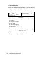
C. How To Read The Screens
Every action of the Radio Service Software is controlled through the use of formatted screen
displays and the function keys on your keyboard. The function keys are the ten keys located on
the left side or along the top of your keyboard marked F1 - F10.
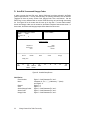
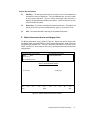
Figure 2 illustrates the screen format used by the Radio Service Software. Each screen is
divided into four areas: Screen Identification Area, Screen Messages Display Area, Screen Data
Entry/Display Area, and Function Key/Selection Display Area.
Screen Identification Area
Screen Messages Display Area
Screen Data Entry/Display Area
F1
HELP
F2
F3
F4
F5
F6
F7
F8
F9
Function Display Selection Area
F10
Exit
Figure 2. Screen Display Format
The Screen Identification Area is the upper left area of the screen display and is sub-divided into
four sections as follows:
•
The first line displays MOTOROLA Radio Service Software.
•
The second line displays the SABER radio name and the model number.
•
The third line displays the current version number.
•
The last line is the MENU PATH. This displays the path the user took to reach the
current screen display.
Getting Started
5
The Screen Message Display Area is in the upper right area of the screen and is further divided
into two sections as follows:
•
Instruction Messages : This message informs you of the next course of action or
provides the range of acceptable values for the current data entry field.
•
Status/Error Messages: Status messages will inform you when the software is
performing non-interactive functions. The Error message informs you that an error has
occurred and how to correct the error condition.
The Screen Data Entry/Display Area is the center part of the display screen where all menus,
data entry, and display of information takes place.
The Function Key/Selection Display Area is the bottom area of the display screen and shows
the function keys F1 - F10 with an abbreviated description of each key's function. If a key has no
use, no text appears beneath the function key title.
D. How To Use The Keyboard
All Radio Service Software keyboard commands are summarized in this section. These function
keys are applicable to changing screens, entering data, and moving between data fields. The F1
HELP function also provides keyboard information. From any screen, you may view this list by
pressing F1 (HELP) and then pressing F2 (KEYBOARD HELP).
6
F1:
F2 - F9:
F10:
ESC:
Help Information
Execute Labeled Function
Return to the PREVIOUS Menu
Return to the MAIN Menu
TAB (or ENTER) :
Shift TAB:
Advance Cursor to Next Data Field
Backup Cursor to Last Data Field
UP / DOWN Arrow Keys:
Shift UP / DOWN Arrow Keys:
Increment / Decrement Value or Selection
Increase the Increment / Decrement Speed
LEFT / RIGHT Arrow:
INSERT:
BACKSPACE:
Move Cursor Within Data Field
Insert Space at Current Cursor Position
Erase Character to the left of Cursor
DELETE:
HOME:
END:
PAGE UP / PAGE DN:
Erase Current Character
Move Cursor To Upper Left Data Field
Move Cursor To Lower Right Data Field
Change Displayed Page
Getting Started
E. The MAIN Menu
The MAIN Menu (Figure 3) is the top level of the program tree as previously shown in Figure 1.
The Radio Service Software provides five basic functions which are selected from the MAIN
Menu:
•
SERVICE: Alignment, Service Aids, Board Replacement
•
GET/SAVE/PROGRAM Codeplug Data From/To Disk/Codeplug
•
CHANGE/CREATE/VIEW Radio Codeplug Data
•
PRINT Codeplug Data
•
SETUP Computer Configuration
Select Function Key F1 - F10
MOTOROLA Radio Service Software
SABER
Model:
Ver. R07.01.00
R05.00.00
Main
MAIN MENU
F1
F2
F3
F4
F5
F6
F7
F8
F9
F10
F1
HELP
F2
ALIGN
-
HELP
SERVICE: alignment, service aids, board replacement
GET/SAVE/PROGRAM codeplug data from/to disk/codeplug
CHANGE/CREATE/VIEW radio codeplug data
PRINT codeplug data
- SETUP Computer Configuration
- EXIT
F3
READ
WRITE
F4
CREATE
F5
PRINT
RPF
F6
F7
F8
F9
SETUP
F10
EXIT
Figure 3. MAIN Menu
Getting Started
7
After making a selection via the function keys, you will be directed to similar sub-menus and/or
data entry screens. From any point in the program, you may always return to the MAIN Menu by
pressing the ESC (Escape) key.
Each programmer function is described briefly in the remainder of this section.
F1
The HELP function gives specific information regarding the current menu or highlighted
data field. By pressing F1, the help menu screen will be generated in which F1 provides
you general help, F2 provides keyboard help, F5 prints out a hard copy of the help
screen, and F9 prints "other" help, or help related to a particular menu.
All HELP functions are explained in detail in Section V.
F2
The SERVICE function allows you to access alignment parameters in which sub-menus
are provided in order to ALIGN RADIO, ALIGN CHANNEL, or ALIGN SCAN CONTROLS.
All SERVICE functions are explained in detail in Section VI.
F3
The GET/SAVE/PROGRAM CODEPLUG DATA FROM/TO DISK/CODEPLUG function
provides all disk and codeplug interfacing. You may either choose from a READ/WRITE
RADIO sub-menu, or a LOAD/SAVE/DELETE Codeplug From Disk sub-menu. The
READ function will read the present radio codeplug data from the radio and generate a
field programmer PC file. The WRITE function actually generates the codeplug data and
writes the present radio personality into the EEPROMS in the radio. The LOAD/SAVE
and DELETE RADIO CONFIGURATION DATA is used to Read codeplug data from an
archived codeplug image on a diskette or hard disk for editing purposes (via
create/change/view function). The LOAD/SAVE is also used to Save a modified codeplug
image back onto the diskette (or hard disk) or to delete a file from disk.
All GET/SAVE/PROGRAM functions are explained in detail in Section VII.
F4
The CHANGE/CREATE/VIEW RADIO CODEPLUG DATA allows all editing of the radio
personality features such as creating, changing, or merely viewing the current radio
codeplug data.
All CHANGE/CREATE/VIEW functions are explained in detail in Section VIII.
F5
The PRINT function produces permanent hard copy records of codeplug configurations. A
printer is required and should be connected to your computer per your instruction manual.
All PRINT functions are explained in detail in Section IX.
F9
The SETUP COMPUTER CONFIGURATION function is used to configure your SABER
Radio Service Software to your particular application. Default disk drives, communication
ports, etc... may be customized to your specific needs.
All SETUP COMPUTER CONFIGURATION functions were explained in Section IV-A.
F10
8
The EXIT function is used to quit the present program and return to the previous menu.
Be sure all desired codeplug changes have been programmed back to the radio, and
that an archive copy has been made. Otherwise all changes will be lost since returning
to DOS erases this data from the computer's memory.
Getting Started
III. HARDWARE INSTALLATION
A. Host Computer And Options Required
The following section provides the hardware and software requirements needed to run the
SABER Radio Service Software .
Computer:
IBM PC or CONVERTIBLE
IBM-XT
IBM-XT/286
IBM-AT
IBM-PS/2: Models 25, 30, 50, 60, 70, or 80
Memory Required:
At least 640k bytes of RAM.
Operating System:
The software requires the DOS Version 3.1 or later to run this package.
Disk Storage:
The software will be available on both 3 1/2" and 5 1/4" (RVN-4002H) media and must be
installed onto a hard disk drive. However, you can also store the data files on either 3 1/2"
and 5 1/4" disks.
Communication Card:
A serial port is also required if personality files are to be read from or written to a radio. The
serial port must be compatible with the IBM asynchronous communications adapter.
Printer:
A parallel interface IBM compatible printer is required if you plan to use the print facilities of
the software.
Monitor:
A monochrome or color monitor compatible with the IBM monochrome display or IBM
CGA/EGA adapter is required.
Hardware Installation
9
B. Optional Hardware Requirements
Additional hardware will be required if it is necessary to read, program, or align a SABER radio.
The following section provides a list of required hardware.
Only one of the two cables is required. Choose the appropriate one for your machine.
- Computer Interface Cable ( 25-pin connector cable ):
#30-80369B71
- Computer Interface Cable ( 9-pin connector cable ):
#30-80369B72
Radio Interface Box ( RIB ):
#RLN-4008A
RIB Power Supply:
#01-80357A57 (110V)
#01-80358A56 (220V)
#60-82728J01 (9V)
Programming Cable:
#RTK-4203A
For Alignment: ( See items listed in your SABER Service Manual)
- Power Meter
- RF Monitor
- Frequency Generator (10 Hz - 10 kHz)
- Battery Eliminator:
#RTL-4224A
- Portable Products Test Set:
#RTX-4005B
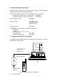
C. Connecting The Radio To The Computer
The SABER radio and the Radio Interface Box (RIB) should be connected to the computer as
described below. Refer to Figure 4.
DOS 3.1
640k RAM
512k
Computer Interface Cable
P/N: 30-80369B71
or B72
To COM 1 or COM2
RS-232 Port
Radio Interface Box
15-Pin
RIB
RLN-4008
25-Pin
Program/Test Cable
RTK-4203A
SABER
RADIO
Figure 4. Connecting the Radio to the Computer
10
Hardware Installation
1. Shut off your computer system before connecting anything to it.
2. Connect one end of the RS-232 cable to the IBM PC (the cable is marked to show you which
end plugs into the computer). Connect the other end of the cable into the RIB.
3. Connect the RIB power supply to the RIB and plug the power cord for the RIB into a power
outlet.
4. Connect the programming cable into the other end of the RIB. (The programming cable has
four terminations but only one will fit into the RIB.) On the same end of the programming
cable as the RIB termination are three other terminations - a round multi-pin connector, a
male BNC type RF connector and a female BNC connector.
5. Attach the male BNC RF connector to a power meter for RF power level measurements, or
an rf monitor for deviation measurements. Note that if you use an extension coax cable to
connect the BNC connector to the appropriate test equipment, you will need to take into
account the rf losses in that extension cable when setting rf power.
6. Connect the round multi-pin connector to the RTX-4005B connector. Use a portable products
test set (or the RTX-4005A test set which has been equipped with the RPX-4665A Field Mod
kit). Select the A position (which is the SABER position) on the test set.
7. Connect the female BNC connector to an audio generator capable of generating frequencies
from 10 Hz to 10 kHz.
8. Remove the battery from the radio (which is turned off) and attach the battery eliminator for
the SABER radio, to the radio under test. Connect the battery eliminator to a 5A, 10V power
supply. Set the power supply to 7.5 +/- 0.1 VDC.
9. Connect the programming cable to the back connector on the radio.
10. Load the SABER Radio Service Software into the computer.
11. Turn the radio on.
12. Later, if you wish to align the radio you must first program the radio to the personality that is
required in the radio. If the radio has already been programmed, then you must first read the
personality of the radio or from disk before you can align it. In either case, a radio
personality file must exist in the work space before the system will allow you to access the
ALIGN menu from the SERVICE screen.
If you had read the personality of the radio, then you must turn the radio off and then back on
prior to aligning it. The system will not allow you to align the radio if the radio is in the
programming mode. For display models, the radio is in the programming mode if the radio
LCD displays the message, ERR x yz (See Appendix -1 on Error messages). Turning the
radio off, and then back on, will take the radio out of the programming mode. If the message
is still there, then see what type of hardware problem has occurred according to the type of
error message as stated in Appendix-1.
Hardware Installation
11
IV. SOFTWARE INSTALLATION
A. How To Install The Software
The Radio Service Software is shipped to you on either two 5 1/4" floppy disks (labeled
PROGRAM DISK 1 and PROGRAM DISK 2) or one 3 1/2" disk (labeled PROGRAM DISK 1).
The software has been designed to give optimum performance while running on a hard disk, but
may be used on a machine with dual-floppy drives. If you have a hard disk, skip to the next
section.
WHILE THE SABER RADIO SERVICE SOFTWARE IS OPERATING IN THE PC
ENVIRONMENT, IT KEEPS SEVERAL FILES OPEN IN THE SYSTEM AT THE SAME TIME.
THE DOS ENVIRONMENT BY DEFAULT LIMITS THE NUMBER OF FILES THAT CAN BE
OPENED AT ANY ONE TIME TO 8. THIS IS NOT SUFFICIENT TO RUN THE SABER RADIO
SERVICE SOFTWARE.
IN ORDER TO INCREASE THE NUMBER OF FILES THAT CAN BE OPENED AT ANY ONE
TIME, IT IS NECESSARY TO DEFINE THIS IN YOUR CONFIG.SYS FILE.
IF THE CONFIG.SYS FILE CURRENTLY EXISTS IN YOUR SYSTEM, IT IS THEN ONLY
NECESSARY TO EDIT THE EXISTING FILE TO ADD THE FOLLOWING LINE.
FILES = 20
IF CONFIG.SYS DOES NOT CURRENTLY EXIST IN YOUR SYSTEM, IT WILL BE
NECESSARY TO CREATE ONE WITH THE SAME LINE AS ABOVE.
REFER TO YOUR DOS MANUAL FOR FURTHER INFORMATION.
12
Software Installation
Hard Disk Installation Procedure
If you are using a hard drive system, use the installation program on Diskette 1 to install the
RSS properly on your hard disk. To run the install program, set the current disk drive to a
floppy drive and insert Diskette 1. At the > prompt, type:
INSTALL <Enter>
and follow the directions given on the screen. The Install program will check for the existence
of the hard disk specified, that sufficient free disk space exists on the hard disk, and if the
subdirectories exist before attempting to create them.
After the installation is complete, move to either the root directory of the hard drive or to the
\RSS\SABER sub-directory and type:
SABER <Enter>
This will start the SABER RSS software.
Software Installation
13
After typing in SABER, the first screen that will come up on your computer is shown below:
MOTOROLA INC.
RADIO SERVICE SOFTWARE
FOR
SABER SERIES RADIO
Version:
Kit:
R07.01.00
RVN4002K
Release Date: 09/01/93
Press Any Key to Continue
COPYRIGHT © MOTOROLA INC. 1988-1993 All Rights Reserved.
Now continue to Section IV-B to complete the configuration procedure.
14
Software Installation
B. How To Configure The Software For Your Computer
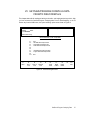
The first time the Radio Service Software is installed on a floppy disk system or the hard disk
system, the program will initially respond with the MAIN menu. To configure your computer press
F9 for SETUP Computer Configuration Menu. The screen as shown in Figure 5 will come up.
The SERVICE SOFTWARE CONFIGURATION Menu has several system options that need to be
setup in your configuration file. This procedure only needs to be setup once when installing the
system. Each function key is explained below in order to configure your computer completely.
MOTOROLA Radio Service Software
SABER
Model:
Ver. R07.01.00
R05.00.00
Select Function Key F1 - F10
Main.Setup
SETUP COMPUTER CONFIGURATION MENU
F1 - Help for Computer Setup
F2
F3 - PC Configuration: Drives, Paths, Ports, etc...
F4
F5
F6
F7 - Screen Color Configuration
F8 F9
F10 - EXIT
F1
HELP
F2
F3
PC
CONFIG
F4
F5
F6
F7
SCREEN
COLOR
F8
F9
F10
EXIT
Figure 5. Setup Computer Configuration
Software Installation
15
F3 -
PC Configuration: Drives, Paths, Ports, etc...
PC Configuration is important in running the SABER Radio Service Software. When F3 is
selected, the screen shown in Figure 6 will come up. Each data field can be selected by
pressing the ENTER key and entering the proper data for that field. "Toggle" selection is made
only on the last entry in which the UP/DOWN arrow keys will toggle between the two data fields
listed.
MOTOROLA Radio Service Software
SABER
Model:
Ver. R07.01.00
R05.00.00
Enter Drive
Main.Setup.PC
PC CONFIGURATION
Archive drive:
A
Archive path:
RSS\SABER\Data
Serial Port:
F1
HELP
F2
COM 1
F3
F4
F5
PRINT
F6
F7
F8
SAVE
F9
RESET
DEFAULT
F10
EXIT
Figure 6. PC Configuration
Use the following steps to configure your computer:
1. Enter the Archive Drive, or default disk drive where you plan to keep your archive files.
For example, if you have a hard disk system and want to save archive files on a floppy
disk in drive A:, enter:
A:
for the Archive Path Name. Press ENTER to continue.
For a floppy disk system, you must enter disk drive B: if you have SABER.EXE in drive A
and MOTOROLA.LBR in drive B.
2. Next, you must enter the Archive Path which is the path name of the archive disk where
all archive files will be kept. On the Screen "\Data" is shown but you may call this
directory any name you wish. Remember to create a directory called "Data" if you enter
this directory name for the Archive Path.
16
Software Installation
3. Use the UP/DOWN arrow keys to select Asynchronous Communications Serial Port
COM 1 or COM 2.
4. To complete the PC computer configuration, press F8 to SAVE the configuration
information to a file on the program disk. Every time you use the Radio Service
Software, the configuration that you SAVED last will be used. At anytime the
configuration may be changed and SAVED.
All selections may be reset to the original values by pressing the F9 (RESET DEFAULT)
function key. Note RESET DEFAULT does NOT save the configuration. If the default
values are desired, you must still save them by pressing F8 for SAVE in the Setup
Computer Configuration Menu. If you do not SAVE, the values in place when you exit
the Configuration screen will persist until you exit the program, or change them again.
5. If you have a color monitor, continue with F7 - Screen Color Configuration. Otherwise,
this completes the software installation procedure.
F7 - Screen Color Configuration
Follow the steps below to configure your screen for the various color options. Press the
F7 function key to access the SCREEN COLOR CONFIGURATION screen as shown in
Figure 7, to enable the color display option and configure your screen colors.
MOTOROLA Radio Service Software
SABER
Model:
Ver.R07.01.00
R05.00.00
Use UP and DOWN arrow keys to select
Main.Setup.Colors
CONFIGURE SCREEN COLORS
Is this COLOR or B & W? -COLOR
Color for Normal Text and Input Data...
Color for Headings............................
Color for Error Messages...................
Color for Status Messages.................
Color for Input Prompts......................
Color for Highlighted Data..................
Color for HELP Messages..................
Color for Screen Border.....................
Color for Screen Background.............
F1
HELP
F2
CHANGE
COLOR
F3
TOGGLE
BLINK
F4
TOGGLE
BRIGHT
F5
INVERSE
VIDEO
F6
F7
F8
SAVE
CONFIG
F9
RESET
DEFAULT
F10
EXIT
Figure 7. Configure Screen Colors
Software Installation
17
In order to configure your screen coloring, first set the monitor type: COLOR or B & W (black
and white). Use the UP/DOWN arrow keys to toggle between the two options of either color or
black and white. Press ENTER to move to the next selection. If you wish to skip any selections
continue to press the ENTER key until you find the selection you want to modify.
Each selection listed can be configured with the function keys at the bottom of the screen except
for SCREEN BACKGROUND. This parameter can only be modified with the F2 key or CHANGE
COLOR. The screen background can have one of eight colors and cannot change its brightness,
like the other selections.
Function Key Descriptions:
F2
Change Color - There are eight different colors to select from which you can select by
pressing the F2 key, continue to press this key to scroll through the different colors.
F3
Toggle Blink - This function toggles the selected item to blink on and off. To disable the
blinking, just press the F3 key again.
F4
Toggle Bright - This function toggles the brightness or intensity of the selected color in
F2. This key just toggles between the original color and another intensity of the same
color.
F5
Inverse Video - This function allows you to switch the colors of the background of the
message and the actual character letters of the message. This key just toggles between
the character letters and the background color of the message.
F8
Save Config - This function saves the options selected on this CONFIGURATION
SCREEN COLORS menu. It is necessary to save these options each time you change
or modify any of the selections.
F9
Reset Default - This function resets the screen back to its original state or default
settings. The default screen is the original screen that comes up once this menu is
selected from the SETUP Computer Configuration menu.
The last step in configuring your computer is to save the values using the F8 key. Press F10 to
return to the SETUP Computer Configuration menu, or ESC to return to the MAIN menu.
18
Software Installation
V. THE HELP SCREEN
Help is available from the MAIN menu and any sub-menu with the F1 function key. The HELP
function gives specific help regarding the current menu or highlighted data field. The help menu
screen provides you with three types of help:
F1 -
From the HELP function, general information is available by pressing this function key.
F2 -
This function key provides help on the different function keys pertinent to the particular
screen shown.
F5 -
PRINT help will create a hard copy of all help information shown on the screen.
F9 -
Other help provides additional help on such things as radio serial number, software
version numbers, cable numbers, etc...
F10 exits the help menu and brings you back to the previous menu. If all the information cannot
fit on one screen, use the PgUp and PgDn keys to page through or page back all available help
information. To indicate the exact size of the particular document or "help" information, the screen
identification area in the upper left corner of the screen states "Page X of Y," where "Y" is the
total number of pages and "X" is the present page number.
The Help Screen
19
VI. SERVICING THE RADIO
All radio alignment procedures are accessed from the SERVICE menu. A radio must be
connected to your computer via a RIB and cables, and the radio turned ON before you will be
permitted to access the SERVICE screens. Refer to the SABER SERVICE AIDS list in Appendix7 for all the service aids, service tools, and recommended test equipment that you may require
to program, align, and test SABER radios.
All SERVICE screens do NOT read and program the radio codeplug directly, you have to use the
READ/WRITE functions before and after using the SERVICE menus.
A. How To Set Up
For setting up to align the radio, follow the procedure in Section III-C: Connecting the Radio To
The Computer, except use the general hardware test equipment shown in Figure 8 for aligning.
Computer Interface Cable
RIB
RLN-4008
P/N 30-80369B71 or B72
Serial Card
IBM PC Computer
Program/Test Cable
Test Equipment
RTK-4203A
Portable
Products
Test Set
RTX-4005B
Saber
Battery Eliminator
RTL-4224A
Figure 8. Test Setup for Alignment Procedure
20
Servicing the Radio
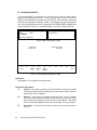
Once you are ready to begin the alignment process, select the SERVICE function (F2) in the
MAIN menu. Once selected, the system will bring up the screen shown in Figure 9. You will see
three menu selections on this screen for Align Radio, Align Channel, and Align Scan. Press the
appropriate function key and a sub-menu will come up with all the available alignment
parameters. Sections VI-B, VI-C, and VI-D explain in detail the function and procedure for
aligning the radio, channels, and scan controls.
MOTOROLA Radio Service Software
SABER
Model:
Ver. R07.01.00
R05.00.00
Select Function Key F1 - F10
Main.Align.
SERVICE / ALIGNMENT MENU
F1 - Help on Alignment
F2
F3 - Align Radio Parameters
F4 - Align Channel Parameters
F5 - Align Scan Controls
F6
F7
F8
F9
F10 - EXIT
F1
HELP
F2
F3
ALIGN
RADIO
F4
ALIGN
CHAN
F5
ALIGN
SCAN
F6
F7
F8
F9
F10
EXIT
Figure 9. Service/Alignment Menu
Servicing the Radio
21
B. Align Radio Parameters
If you selected the ALIGN RADIO function in the SERVICE screen, the system will display the
screens shown in Figures 10a and 10b. These screens will allow you to adjust 14 parameters
(including Secure Deviation Offset for a SECURENET radio). Each of these parameters are
explained below, followed by the procedure needed to set these parameters correctly for the
radio being aligned. Note that on certain alignment procedures, the last step states "Reprogram
radio." This means that after all alignment is completely finished, you must reprogram the radio.
You do not have to reprogram the radio after each parameter is aligned.
MOTOROLA Radio Service Software
SABER
Model
Ver. R07.01.00
R05.00.00
Use UP / DWN Arrows to Change Value.
PGUP /PGDN to Change Rapidly.
Main.Align.Radio
ALIGN
AL
I G N RADIO
R A D IPARAMETERS
O PARAMETERS
Oscillator WARP
Low POWER level
Medium POWER level
High POWER level
Special POWER level
Low Battery Threshold
Battery Save Squelch
Secure Deviation Offset
0
F1
HELP
10
F2
20
F3
30
40
00
00
00
00
00
00
00
00
50
60
F4
F5
F6
MORE
PRINT
ALIGNMENTSSCREEN
Power Bias is HIGH
Power Bias is HIGH
Power Bias is HIGH
Power Bias is HIGH
70
80
90
F7
F8
TOGGLE
POWER BIAS
100%
F9
F10
EXIT
Figure 10a. Align Radio Menu 1
MOTOROLA Radio Service Software
SABER
Model
Ver. R07.01.00
R05.00.00
Use UP / DWN Arrows to Change Value.
PGUP /PGDN to Change Rapidly.
Main.Align.Radio
A ALIGN
L I G N RADIO
R A D IPARAMETERS
O PARAMETERS
Audio Processing
Sidetone Volume
DTMF Dial Delay
DTMF Tone on Time
DTMF Tone off Time
Mic Gain (Only if H852)
0
F1
HELP
10
F2
20
F3
30
40
50
FF
00
00
00
00
0dB
60
F4
F5
F6
MORE
PRINT
ALIGNMENTSSCREEN
70
(Disabled)
80
F7
F8
TOGGLE
POWER BIAS
Figure 10b. Align Radio Menu 2
22
Servicing the Radio
90
100%
F9
F10
EXIT
Each parameter can be adjusted one of three ways:
The UP arrow key will increase the parameter value. The DOWN arrow key will decrease the
parameter value.
The PGUP key will increase the parameter with a rate increase of 10% present value. The PGDN
key will decrease the rate of decrease by 10 % present value.
The UP/DOWN keys may also act as a toggle between two given parameter values or choices
such as "ON/OFF" or "YES/NO."
1.
Oscillator Warp
This adjustment sets the reference oscillator so that the transmit and receive frequencies are
set correctly for the radio. Since the SABER radio is a synthesized radio, this one adjustment
will set ALL the receive and transmit frequencies in the radio correctly, once you set oscillator
warp correctly on one frequency. When aligning Oscillator Warp, you can see the change in
frequency during the alignment process or in "real time." You do not have to reprogram the
radio to see the immediate frequency change. To perform this adjustment, use the
procedure given below.
(a) Follow the Setup Procedure in Section VI-A, Fig. 8.
(b) Key up the radio by pressing the push-to-talk (PTT) button on the radio or by using the
PTT switch on the test set. Ensure that you have the RF connector terminated in a 50
ohm load and connected to a frequency counter so that you can measure the transmit
frequency. Determine the frequency error between the desired channel frequency and
the frequency measured.
(c) De-key the radio.
(d) Calculate the number of steps required to bring the radio on frequency using the
following formulas:
For UHF radios: number of steps = (frequency error in Hz) / 180
For VHF radios: number of steps = (frequency error in Hz) / 80
NOTE: A negative frequency error indicates that the frequency will have to be increased
by stepping up with the UP arrow key (or PGUP). A positive frequency error indicates
that the frequency will have to be decreased by stepping down with the DOWN arrow
key (or PGDN).
(e) Select the OSCILLATOR WARP item on the screen by using the ENTER or TAB key.
The selected item will be highlighted in inverse video.
(f) Use the UP or DOWN arrow key to decrease or increase the value of the number shown
by the number of steps calculated above. Note that the number shown is a hexadecimal
number and the numbers will go from 00 through FF. As an example, if the original value
shown is 44, pressing the UP arrow key will cause the number to scroll through the
following sequence - 45, 46, 47, 48, 49, 4A, 4B, 4C, 4D, 4E, 4F, 50, 51, etc...
If you had calculated that 13 positive steps were required to bring it on frequency, you
can press and release the UP arrow key 13 times. Or, you can hold the UP arrow key
down and the numbers will scroll up in value and once you have reached the desired
value, release the key. You may also use the PGUP key to increment by 10.
(g) Key the radio and check the frequency. Repeat the procedure if necessary. Ensure that
the measured frequency is within the specified frequency window for that radio model.
Servicing the Radio
23
2. Power Level
Four different power levels can be adjusted in the SABER radio - the low, medium, high, and
special power levels. (Each channel in the radio can have unique power level assignments
made on the Radio Channel Information screen described in Section VIII-C. ) Note that the
standard low and high power settings for UHF are 2.0W to 5.0W respectively, and for VHF
the power settings are 2.5W to 6.0W respectively. Even though these are the standard
settings, you can set the power levels to any value up to the maximum setting allowed. Note
that you can set both the low and high power levels to the same value if you wish, which
allows both settings to have either a low power setting, a high power setting, or any power
level up to the maximum level allowed.
Use the ENTER key to select the power setting you wish to adjust: LOW, MEDIUM, HIGH,
or SPECIAL. Once you have selected the appropriate power level, (the selected power level
setting will be highlighted in inverse video), follow the procedure given below. When aligning
the Power Level, you can check the power output during the alignment process or in "real
time." You do not have to reprogram the radio to see the immediate power change.
(a) Follow the Setup Procedure in Section VI-A, Fig. 8.
(b) Before aligning the power level, select the proper TOGGLE POWER BIAS with the F7
function key according to the table below:
Select Power Bias High:
> 2 W. for High power radios
Select Power Bias Low:
< 2 W. for High power radios
OR
> 1 W. for Low power radios
< 1 W. for Low power radios
(c) Choose a channel with a frequency as close to the center of the band as possible, or the
center frequency of the radio to be aligned. Set the radio to that channel.
(d) Connect the RF BNC connector to an RF power meter.
(e) Key up the radio and measure the RF power.
(f) De-key the radio and use the arrow keys to adjust the power to the desired power
setting. The UP arrow key (or PGUP) will increase the power level setting value if the
measured power is lower than the desired value while the DOWN arrow key (or PGDN)
will decrease the power level value if the measured power is higher than the desired
value.
(g) Re-key the radio and measure the output power.
(h) Repeat the procedure until the power level is at the desired level.
(i) Check power output at the band edges (by going to the channel closest to the band
edges) to ensure that you meet the power requirements at those frequencies. If required,
return to the center frequency and adjust the power so that you meet the requirement
across the band.
Once you have completed one of the power level setting adjustments, select the other power
level setting and repeat the above procedure to obtain the desired power setting.
24
Servicing the Radio
3.
Low Battery Threshold
Low Battery Threshold determines at what voltage level the LED will blink to indicate that the
battery voltage has fallen below the preprogrammed value in transmit mode. On the display
of your radio, you will see a battery flashing symbol. When aligning Low Battery Threshold,
you will not be able to test the voltage level until you reprogram the radio first. In order to
align this parameter, follow the steps below:
(a) Set up a battery block for the radio along with the Setup Procedure in Section VI-A, Fig. 8.
(b) Use the UP/DOWN arrow keys or PGUP/PGDN to increase/decrease these values. The
default value for this parameter is $9E which corresponds to 6.5 volts.
(c) Reprogram radio if finished with ALL alignment functions.
4.
Battery Save Squelch
This adjustment is used to set the carrier squelch level at which the receiver will operate
when the radio is in battery save mode. Set the value to optimize battery save performance
for the particular system in which the radio will operate. When aligning Battery Save
Squelch, you will not be able to test the squelch level until you reprogram the radio first. In
order to align battery save squelch, follow the steps below:
(a) Follow the Setup Procedure in Section VI-A, Fig. 8.
(b) In order to align this parameter, you MUST be in Battery Save Squelch Mode which can
be done by first going into ALIGN CHANNEL and enabling the Battery Save Enable bit.
Return to ALIGN RADIO and reselect this alignment option.
(c) The Battery Save Squelch bytes contain the squelch level to be used while in battery
save mode. The default value for this byte can be determined as follows:
First find the minimum squelch among the channels defined for the radio and use this
value to index the following table to determine the value of Battery Save Squelch.
Minimum Squelch Level
$00
$01
$02
$03
$04
$05
$06
$07
$08
$09
$0A
$0B
$0C
$0D
$0E
$0F
Battery Save Squelch Level
$00 (minimum squelch)
$01
l
$02
l
$03
$03
l
$03 --open squelch-$04
$05
$06
$07
$08
$0A
$0B
$0C
$0D
$0E (maximum squelch)
Servicing the Radio
25
Other values for the Battery Save Squelch level may be selected with the RSS. The squelch
values can range from $00 to $0F where $00 is the minimum squelch setting.
(d) To ensure the radio is in the battery save Mode, wait until the radio unmutes at carrier
and wait the proper dwell time before injecting a signal at the specific level for testing. If
this time is not accounted for, then you may still be in dwell mode. Dwell mode can
range from approximately 5 to 8 seconds.
(e) Use the UP/DOWN or PGUP/PGDN arrow keys to increase/decrease these values.
(f) Reprogram radio if finished with ALL alignment functions.
5. Audio Processing
This adjustment sets the volume level at which the audio processing filter will cut in to cause
a roll-off of audio frequencies below 1kHz. The audio processing filter is a high pass filter
with a high frequency corner at 1kHz. When this audio processing filter kicks in, audio that
would normally be distorted at high volume levels becomes more intelligible or audible.
When aligning Audio Processing, you will not be able to test the audio level until you
reprogram the radio first. In order to align this parameter follow the steps below:
(a) Follow the Setup Procedure in Section VI-A.
(b) First determine at what level you wish to set the volume level to meet radio environment .
(c) A nominal level to begin testing is at $C0, where levels below $C0 have regular audio,
and levels above $C0 enables the audio processing filter. The system default value is
$FF to disable audio processing, and $EB is the maximum value to enable audio
processing. The valid range for aligning is $00 - $FF ( or 0 - 255).
(d) Use the UP/DOWN or PGUP/PGDN arrow keys to increase/decrease these values.
(e) Reprogram radio if finished with ALL alignment functions.
6. Sidetone Volume
This parameter controls the sidetone volume level. Its value ranges from $00 to $FF in steps
of 1. To see the effect of the change, the radio must first be reprogrammed.
(a) Follow the setup procedure in Section VI-A, Fig. 8.
(b) Determine the sidetone volume level desired and use the UP/DOWN or PGUP/PGDN
arrow keys to increase/decrease the level.
(c) Reprogram radio if finished with ALL alignment functions.
26
Servicing the Radio
7.
DTMF Dial Delay
This parameter controls the DTMF pretime. Its value ranges from $00 to $FF in steps of 1.
To see the effect of the change, the radio must first be reprogrammed.
(a) Follow the setup procedure in Section VI-A, Fig. 8.
(b) Determine the dial delay desired and use the UP/DOWN or PGUP/PGDN arrow keys to
increase/decrease this delay.
(c) Reprogram radio if finished with ALL alignment functions.
8.
DTMF Tone On Time
This parameter sets the DTMF tone duration. Its value ranges from $01 to $FF (1 to 255) in
5 millisecond units (5 ms to 1.275 seconds). The default value is $0C, which is 60 ms.
When aligning DTMF Tone On Time, you will not be able to test the ON time until you
reprogram the radio first.
(a) Follow the Setup Procedure in Section VI-A, Fig. 8.
(b) Determine what tone duration you wish to have and use the UP/DOWN or PGUP/PGDN
arrow keys to increase/decrease these values.
(c) Reprogram radio if finished with ALL alignment functions.
9.
DTMF Tone Off Time
This parameter defines the time between DTMF tones. The value for this parameter ranges
from $01 to $FF (1 to 255) in 5 ms units (5 ms to 1.275 seconds). The default value is $1C,
which is 140 ms. When aligning DTMF Tone Off Time, you will not be able to test the OFF
time until you reprogram the radio first.
(a) Follow the Setup Procedure in Section VI-A, Fig. 8.
(b) Determine what tone duration you wish to have and use the UP/DOWN or PGUP/PGDN
arrow keys to increase/decrease these values.
(c) Reprogram radio if finished with ALL alignment functions.
10. Secure Deviation Offset
This parameter defines a deviation adjustment that is applied during coded transmissions.
You can only align this value if you have a radio that has a voice privacy module installed. If
you selected option H432 in "Radio Feature Options," then this adjustment is not necessary.
The default value is 0. When aligning Secure Deviation Offset, you can see the change in
deviation during the alignment process or in "real time." You do not have to reprogram the
radio to see the immediate deviation change. To perform this adjustment, follow the
procedure given below.
(a) Follow the Setup Procedure in Section VI-A, Fig. 8.
Servicing the Radio
27
(b) Before proceeding, you must have previously aligned the VCO and Reference
Modulation. If you have not done this yet, press ESC to return to the SERVICE menu,
then follow the instructions in the section "Align Channel." Upon returning to the
SERVICE menu, reselect "Align Radio" and proceed.
One additional requirement is that your radio must have a "KEY" loaded for coded
transmission. To check this, select a channel that is programmed (SLAVED) for coded
transmission or place the clear/coded switch in the coded position and key the radio. If
there is no key present, the radio will continuously emit short alert tones indicating a "key
fail" condition. On SABER models with a display, the key fail message will display as
long as the radio is keyed up.
NOTE
After aligning VCO, REF MOD and returning to the align radio screen, do not
change channels as this will result in the old tuning information being used.
(c) Select the Secure DEVIATION OFFSET item on the screen by using the ENTER key.
The selected item will be highlighted in inverse video.
(d) Place the clear/coded transmission switch in the coded position.
(e) Connect the RF BNC connector to a 50 ohm load and to a service monitor ( with Secure)
so that you can measure deviation.
(f) Select the Secure function on the service monitor. Increase or decrease the deviation
offset value by one step using the up or down arrow key. This enables the RSS to strap
this channel coded if you just left the align channel screen which straps the radio clear.
(g) Key the radio, measure and record the Secure deviation. Label the result as DVP DEV.
(h) De-key the radio.
(i) The Secure deviation measured should be adjusted to be 4 KHz +/- 500.
(j) To calculate the Secure Deviation Offset adjustment required, apply the formula below to
the measured deviation:
Steps = LOG
10
(DVP DEV / 4000) * 20 / .35
(k) Use the DOWN or UP arrow keys to decrease or increase the value shown on the
display for Secure deviation. Note that the number shown is in hexadecimal. The value
of this number ranges from F0 to 1F. As an example, if the starting value is F9, repeated
pressing of the UP arrow key would produce the following sequence - F9, FA, FB, FC,
FD, FE, FF, 00,01, 02, 03, 04, 05, etc..
(l)
Re-key the radio, and measure the deviation again. Repeat the adjustment, until
measured deviation is 4 KHz. Note that if the channel you're using has not been
properly aligned beforehand, it may not be possible to correctly align the Secure
Deviation Offset.
(m) If the Secure Deviation Offset adjustment does not provide enough "steps" for you to
align, then the channel is not aligned properly, or the radio needs service.
(n)
28
Reprogram the radio.
Servicing the Radio
11. MICROPHONE GAIN
This parameter is used when sending out the voice signal. There are 4 different values from
which you can choose : -3 dB, 0 dB (default), +3 dB, and +6 dB. The radio has to be
reprogrammed to see the effect of the change. This will only work on radios with the H852,
6D master option enabled or the H549, 8D master option enabled.
(a) Follow the setup procedure in Section VI-A, Fig. 8.
(b) Determine the microphone gain you wish to have and use the UP/DOWN or
PGUP/PGDN arrow keys to increase/decrease these values.
(c) Reprogram radio if finished with ALL alignment functions.
Once you have completed the radio level alignment adjustments, press the F10 key to
return to the SERVICE menu.
Servicing the Radio
29
C. Align Channel Parameters
In order to align the channel level parameters, squelch, VCO Modulation, Reference Modulation,
and Battery Save Enable, select the ALIGN CHANNEL PARAMETERS item in the ALIGN menu.
These parameters are called channel level parameters because they have to be adjusted on
every channel as opposed to the radio level parameters which apply to all the channels in the
radio. Once the ALIGN CHANNEL menu has been selected, the system will display the screen
shown in Figure 11. At the bottom of the screen the current zone/channel combination being
aligned will be displayed. Merely select the next zone/channel on the radio to be aligned and the
screen will update the display.
MOTOROLA Radio Service Software
SABER
Model
Ver. R07.01.00
R05.00.00
Use UP / DWN Arrows to Change Value.
PGUP /PGDN to Change Rapidly.
Main.Align.Channel
ALIGN CHANNEL PARAMETERS
Squelch Level
VCO Modulation
Reference Modulation
Battery Save Enable
0
10
20
30
Rx: 150.00 MHz
Sq.: 167.9 6Z
F1
HELP
F2
COPY
TO ALL
40
50
00
00
00
00
60
70
80
90
Zone01: Channel 001
Sq.: NOT DETECTED
F3
COPY TO
ZONE
F4
F5
PRINT
SCREEN
F6
COPY ALL
TO ALL
100%
Tx: 150.000 MHz
Sq.: 167.9 6Z
F7
F8
F9
F10
EXIT
Figure 11. Align Channel Menu
Note that on certain alignment procedures, the last step states "Reprogram radio," this means
AFTER all alignment is completely finished, you must reprogram the radio. You do not have to
reprogram the radio after each parameter is aligned.
Function Key Descriptions:
F2
Copy to all - This function key will copy a particular alignment parameter value to all
the channels. For example, If VCO for the current channel is $1F, pressing F2 will set
VCO to $1F in all channels.
F3
Copy to zone - This function key will copy the particular alignment parameter value to
all the channels in the current zone.
30
Servicing the Radio
F5
Print screen - This function key will print out everything shown on the screen.
F6
Copy all To all - This function key will copy EVERY alignment parameter in the current
channel to all the channels in the radio regardless of zone.
The lower portion of the screen contains some additional information that will be helpful in the
alignment process. The SQ field lets the user know whether or not squelch has been detected
by the radio's receiver. This allows you to set threshold squelch on those channels which are PL
protected. This means that you will not need to have any carrier squelch channels programmed
into the radio in order to set the squelch.
1. Squelch
When aligning squelch on PL/DPL channels, use the squelch (SQ) field in the lower portion
of the screen to determine when the radio squelches. On carrier squelch (CSQ) channels,
you can also listen to the reference speaker in the portable products test set. When aligning
Squelch, you can hear the change in the squelch level during the alignment process or in
"real time." You do not have to reprogram the radio to hear the immediate change.
(a) Follow the Setup Procedure in Section VI-A, Fig. 8.
(b) Select any channel on the radio.
(c) Select the SQUELCH function in the ALIGN CHANNEL screen.
(d) With no RF signal applied to the radio, set the squelch value to $0 by using the DOWN
arrow key. You should hear noise through the speaker in the test set (CSQ) and SQ
should be OFF (CSQ & PL/DPL). Set the switch on the test set at the load position
instead of the speaker position and the volume on the radio set at rated audio.
(e) Connect the RF BNC connector to the service monitor so that you can measure SINAD.
(f) Increase the RF, on the correct carrier frequency, until 8dB to 12dB SINAD is measured.
(g) Increment the squelch value by using the UP arrow key until the radio squelches (no
noise present or SQ is ON). The valid range for squelch is from $0 to $0F, with a default
value of $09.
(h) You can now set the same squelch value to all the channels in the radio by pressing the
F2 key. Pressing the F2 key will cause the current squelch value to be copied over to all
the other channels in the radio. If you want to make the squelch value different on any
other channel, you will have to go to that channel and set the squelch by following the
procedure given above.
Servicing the Radio
31
2. VCO and Reference Modulation Alignment
When adjusting deviation, two separate adjustments are required - one for VCO modulation
and the other for REFERENCE modulation. When aligning VCO and Reference Modulation,
you can measure the deviation during the alignment process or in "real time." You do not
have to reprogram the radio to measure the change. However, you will have to reprogram
the radio to make these changes permanent. Do NOT turn off the radio while aligning this
parameter. The procedure given below will go through both of these adjustments.
(a) Follow the Setup Procedure in Section VI-A, Fig. 8.
(b) Connect the RF BNC connector to a 50 ohm load and to a service monitor so that you
can measure deviation.
(c) Select the VCO Modulation function on the ALIGN CHANNEL menu using the ENTER
key.
(d) Using the UP arrow key, set the VCO Modulation value to $1F.
(e) Select the REFERENCE Modulation function on the ALIGN CHANNEL menu by using
the ENTER key.
(f) Using the UP arrow key, set the REFERENCE Modulation value to $0F.
(g) Now select the VCO Modulation function on the ALIGN CHANNEL menu.
(h) Apply a 1 kHz, 25 mVrms tone to the external microphone port on the test set. Measure
this level at the AC/DC metering jacks on the Portable Test Set. Measure deviation by
keying up the radio.
(i) De-key the radio and adjust the VCO modulation value (decrease the value if the
measured deviation is higher than the required value) by using the DOWN key to
decrement value. The valid range for this parameter is from $00 to $1F with a default
value of $1C.
(j) Re-key the radio and measure the deviation. Repeat the procedure (this step and the
step above this) until the required deviation is reached.
(k) Apply a 0.355 Vrms, 1 kHz tone to the auxiliary transmit port on the radio (the female
BNC connector). The signal level should be measured with the audio generator
connected to the radio. To do this you will have to use a T-connector so that you can
simultaneously apply the signal to the radio as well as applying it to the AC meter.
(l) Select the REFERENCE Modulation function on the ALIGN CHANNEL menu by using
the ENTER key. By selecting this function, the radio service software enables the
auxiliary port of the radio after being keyed.
NOTE
Reference modulation cannot be aligned on channels that have MDC signalling
enabled. On completion of the MDC signalling, the radio disables the auxiliary port.
(m) Key the radio, and measure this deviation and note it as DEV 1. De-key the radio.
(n) Remove the 1 kHz tone and apply a 0.355Vrms, 20 Hz tone to the auxiliary port.
(o) Key the radio, and measure this deviation and note it as DEV 2. De-key the radio.
32
Servicing the Radio
(p) Adjust the REFERENCE Modulation value by using the DOWN arrow key. Repeat the
step above until DEV 2 = DEV 1.
3. Battery Save Enable
Battery Save Enable allows you to enable the Battery Save Squelch option in ALIGN RADIO
for a particular channel. The battery save will be turned off while scan is activated, and when
scan is deactivated this function becomes enabled on that channel and resume its
programmed state. When aligning Battery Save Enable, you can notice the change during
the alignment process or in "real time." You do not have to reprogram the radio to see the
immediate change. In order to enable this parameter, follow the steps below:
(a) Follow the Setup Procedure in Section VI-A, Fig. 8.
(b) Use the UP/DOWN arrow keys to toggle this option.
(c) Invoke a new channel to check this change, or key up and de-key the radio.
D. Align Scan Controls
If you had selected the ALIGN SCAN CONTROLS function in the SERVICE screen, the
system will display the screen shown in Figure 12. These screens will allow you to align
Scan monitor hold time, Scan receive response time, Scan transmit response time, and Scan
priority squelch. Each of these parameters are explained below, followed by the procedure
needed to set these parameters correctly for the radio being aligned. Note that on certain
alignment procedures, the last step states "Reprogram radio," this means AFTER all
aligning is completely finished you must reprogram the radio. You do not have to reprogram
the radio after each parameter is aligned.
MOTOROLA Radio Service Software
SABER
Model
Ver. R07.01.00
R05.00.00
Use UP / DWN Arrows to Change Value.
PGUP /PGDN to Change Rapidly.
Main.Align.Scan
ALIGN SCAN PARAMETERS
0
F1
HELP
F2
10
20
F3
Monitor Hold Time
03
Receive Response Time
03
Transmit Response Time
03
Priority Squelch
08
30
F4
40
50
F5
PRINT
SCREEN
60
F6
70
F7
80
90
F8
100%
F9
F10
EXIT
Figure 12. Align Scan Menu
Servicing the Radio
33
The only function key here that needs to be explained is PRINT SCREEN (F5) which will
print out a hard copy of the screen shown.
Each parameter can be adjusted one of three ways:
The UP arrow key will increase the parameter value. The DOWN arrow key will
decrease the parameter value.
The PGUP key will increase the parameter with a rate increase of 10 times its present value.
The PGDN key will decrease the rate of decrease by 10 times its present value.
In the following sections below, each alignment parameter with its proper aligning procedures
are explained.
1.
Scan Monitor Hold Time
Monitor Hold Time determines how long the radio will remain on the monitored channel once
the monitor button is released. During monitor hold time, squelch and PL are not defeated
unless permanent monitor has been engaged. After Monitor Hold Time expires, permanent
monitor is released and normal channel scan resumes. To align this scan parameter, follow
the steps below:
(a) Set up according to Section VI-A, Fig. 8 and select the SCAN MONITOR HOLD TIME
option in the Align Scan Menu.
(b) Increment or decrement the time parameter accordingly using the UP (or PGUP) or the
DOWN (or PGDN) arrow keys.
(c) Valid time range is from $01 to $3C (1 to 60 seconds) with a default value of $03 or 3
seconds.
(d) Reprogram radio if finished with ALL alignment functions.
34
Servicing the Radio
2.
Scan Receive Response Time
After a message is received while scanning, a programmable time interval (0 to 60 seconds
in 1 second steps) will be in effect called the Receive Response Time. Within this time, the
radio will not resume scan but will continue to monitor the mode of the last received message
due to the likelihood of receiving (or wanting to transmit) a response. Transmission during
this interval will occur on the mode being monitored rather than on the Preassigned Transmit
Mode. Priority modes will continue to be sampled during this time but other modes will not
be scanned. To align this scan parameter follow the steps below:
(a) Set up according to Section VI-A, Fig. 8 and select the SCAN RECEIVE RESPONSE
TIME option in the Align Scan Menu.
(b) Increment or decrement the time parameter accordingly using the UP (or PGUP) or the
DOWN (or PGDN) arrow keys.
(c) Valid time range is from $01 to $3C (1 to 60 seconds) with a default value of $03 or 3
seconds.
(d) Reprogram radio if finished with ALL alignment functions.
3. Scan Transmit Response Time
After transmitting a message while scanning, a programmable time interval (0 to 60 seconds
in 1 second steps) will be in effect called the Transmit Response Time. Within this time, the
radio will not resume scan (except for priority samples) but will continue to monitor the last
transmitted mode due to the likelihood of receiving a response. Functionally, there are 2
differences between the Transmit and Receive Response Times:
(a) Transmitting during the TRT will not change the floating priority.
(b) The timer values can be different.
To align this scan parameter follow the steps below:
(1) Set up according to Section VI-A, Fig. 8 and select the SCAN TRANSMIT RESPONSE
TIME option in the Align Scan Menu.
(2) Increment or decrement the time parameter accordingly using the UP (or PGUP) or the
DOWN (or PGDN) arrow keys.
(3) Valid time range is from $01 to $3C (1 to 60 seconds) with a default value of $03 or 3
seconds.
(4) Reprogram radio if finished with ALL alignment functions.
Servicing the Radio
35
4. Scan Priority Squelch
This value corresponds roughly to the squelch values which are 'aligned' using the align
channel window of the Radio Service Software. The priority squelch level is used when
checking priority channels while the radio is unmuted on an active channel. Sensitivity to
priority channels in the unmuted state is affected by this value. Lower values will make the
radio more sensitive, but too low a value may cause falsing. The default value is 8 and
should only be changed if difficulties with priority sensitivity are encountered. To align this
scan parameter, follow the steps below:
(a) Set up according to Section VI-A. and select the SCAN PRIORITY SQUELCH option in
the Align Scan Menu.
(b) Increment or decrement the time parameter accordingly using the UP (or PGUP) or the
DOWN (or PGDN) arrow keys.
(c) Valid range is from $0 to $0F (0 to 15) with a default value of $08 (or 8).
(d) Reprogram radio if finished with ALL alignment functions.
36
Servicing the Radio
VII. GET/SAVE/PROGRAM CODEPLUG DATA
FROM/TO DISK/CODEPLUG
This chapter deals with all reading and writing to the radio, and loading and saving to disk. After
you have selected the Get/Save/Program Codeplug data From/To Disk/Codeplug, or the F3
function key from the MAIN menu, the system will bring up the screen shown in Figure 13.
MOTOROLA Radio Service Software
SABER
Model:
Ver. R07.01.00
R07.00.00
Select Function Key F1 - F10
Main.Get/Save/Prog.
READ / PROGRAM (LOAD / SAVE) MENU
F1
F2
F3
F4
F5
F6
F7
F8
F9
F10
F1
HELP
F2
GET A
FILE
- Help
- GET Radio Personality from Disk
- SAVE Radio Personality to Disk
- Delete Radio Personality from Disk
-
Read Radio Personality from Radio
Program Radio Personality to Radio
- EXIT
F3
SAVE A
FILE
F4
DELETE
FILE
F5
F6
LOAD
SAVE
F7
READ
RADIO
F8
PROG
RADIO
F9
F10
EXIT
Figure 13. Get/Save/Program Menu
Get/Save/Program Codeplug Data
37
A. The READ function
The READ function will read the radio codeplug data from the radio and generate an RSS
PC file. In order to read the codeplug, you need to connect the radio to the system. To read
the radio, follow the setup procedure shown in Figure 4.
•
Make sure the radio is not in scan mode.
•
Regardless of the type of radio model being read back (whether a SABER I, II, or III), the
programmer will always read the contents of the CORE processor first. The system will
display the software version level of the CORE processor being read,for example:
CORE 5d , or 6d, etc...
•
After reading the CORE, the system will read the COPE processor followed by the
contents of the external EEPROM. This process will only occur on SABER II and III
models.
•
After the contents of the radio have been read back, the system will convert this data into
the radio personality file. As the system is building the RPF, several messages will
appear on the screen showing the process of the "build." Shown below in Figure 14 is
a sample screen of READ radio.
MOTOROLA Radio Service Software
SABER
Model:
Ver. R07.01.00
R05.00.00
Accessing Serial Bus.
Main.Get/Save/Prog.Read/Prog. Read
READ DATA FROM A RADIO
0%
Reading CORE 6D
Reading COPE internal
Reading COPE external
F1
F2
F3
F4
100%
100%
................................................
................................................
................................................
F5
F6
F7
F8
F9
F10
Figure 14. Read Radio Display
Note: Before reading the radio, a message may appear instructing you to press the three top
keys down on the keypad (for a SABER II and III) simultaneously and turn the radio off and
back on to get an ERR X YZ message on the display. Don't worry about the message unless
the READ radio function does not execute. If the error message does not disappear or the
READ function locks up, refer to Appendix-1, "ERROR MESSAGES."
38
Get/Save/Program Codeplug Data
B. The WRITE function
The WRITE function is used to program the radio, using the current radio personality data.
The radio personality data may have come from disk, been read from the radio, or been
created using the RSS.
Before programming can begin, the radio must first be connected through a radio interface
box (RIB) to the IBM PC, and turned on. Refer to Figure 4 and Section III-C for
interconnection information.
The write-to-radio process consists of two parts. In the first part, the radio personality file
(RPF) is converted into codeplug(s) for the radio. During this phase, several process/status
messages are displayed in the message window. These messages are of no interest unless
an error is encountered during the conversion process.
In the second part of the write process, the codeplug(s) generated by the conversion process
are transferred to the radio. In the case of a SABER I radio, only one codeplug is generated
and written to the radio; in all other radio models, three codeplugs are generated.
Before conversion and programming begins, the RSS will prompt you to make sure that the
current radio personality matches the radio to be programmed. This is normally
accomplished by comparing the model number displayed by the RSS with the model number
on the radio. Make sure the radio is not in scan mode before proceeding.
The RSS will also prompt you to select the source for radio alignment data. The radio
alignment data may come from the RPF (F2), or the radio about to be programmed (F6).
Using SHIFT - F6 the RSS will also extract the unit ID from the radio. For additional
information on this subject, see the "Extraction" section on the following page.
For some radio models, the RSS will request that the radio be placed in the "programming"
mode. To accomplish this:
1. Turn the radio off.
2. Press the MENU, SELECT, and ENTER keys simultaneously and hold them down.
3. Turn the radio on and release the three keys.
4. Check that the radio now displays "ERR X YZ" ("X YZ" will normally be "1 00")
For other models, the radio will be automatically placed in the "programming" mode by the
RSS. In this case, the display will change to "ERR X YZ," and the battery annunciator will
blink. This is normal operation, and does not indicate that the battery is low.
During the radio programming process, the RSS will display information about the
component being programmed, and a graphic indicator of the percent of programming
completed. Figure 15 shows a typical screen for programming a radio with display (SABER II
or III). In Figure 15, the "CORE" is the transceiver microprocessor and the "COPE" is the
display microprocessor. In SABER I radios there is no display processor, so the messages
for programming the COPE will not appear.
Get/Save/Program Codeplug Data
39
MOTOROLA Radio Service Software
SABER
Model:
Ver. R07.01.00
R05.00.00
Accessing Serial Bus.
Main.Get/Save/Prog.Read/Prog.Program
The RPF file conversion is complete.
WRITE DATA TO A RADIO
0%
0%
Programming COPE Internal
Programming COPE External
Programming CORE 6D
6d
F1
F2
F3
F4
F5
100%
100%
................................................
................................................
................................................
F6
F7
F8
F9
F10
Figure 15. Write Data to Radio
When programming is complete, the RSS will revert to the "READ/PROGRAM" menu, the
radio will automatically reset, and the radio display will clear. If the display still shows an
"ERR X YZ" message after programming is complete, try reprogramming the radio. If the
error condition persists, contact your Motorola service representative, or see Appendix-1 for
a description of the error code.
Extraction:
The extraction feature enables you to easily change personalities in a radio without having to
realign the radio. During the extraction process, the RSS reads all the alignment data from
the radio to be programmed. This alignment data is then applied to the current radio
personality, which is then converted to codeplug(s) and written to the radio in the normal way.
In order to better understand the extraction process, an explanation of the normal alignment
process is necessary. First, assume that you have just created a new radio personality. The
RSS, not knowing what radio the personality is destined to occupy, inserts "default"
alignment values into the personality. These default values are necessary to ensure that a
radio will function when programmed with the personality. Next, assume that you must put
this personality into a radio that has never been aligned. You will write the personality to the
radio and, when prompted, select "F2 - Use Programmer Tuning Values." This is necessary
because the radio has never been aligned, and there are no existing alignment values to
extract from the radio.
40
Get/Save/Program Codeplug Data
Next, you will align the radio using the functions provided in the "SERVICE/ALIGNMENT"
menus. While you are aligning the radio, the alignment values are stored in the RPF. Finally,
when you have finished the alignment, you will again write to the radio. When prompted to
select F2 or F6, you will again select F2. Remember, the results of your alignment were
stored in the RPF, so it no longer contains the default values placed there during personality
creation, but instead contains the results of the alignment.
Now, assume that you want to put the same personality into another radio. This time,
however, the radio to be programmed is already properly aligned; it just has a different
personality. When prompted to select F2 or F6, you will select "F6 - Extract Alignment Value
From Radio." If you had selected F2 instead, the radio would have been programmed with
the alignment values of the previous radio and you would have had to align it again.
Selecting F6 instructs the RSS to "extract" (read) the alignment values from the radio to be
programmed, and put those values into the RPF. The "new" personality has been aligned to
fit the second radio, and the resulting personality is converted to codeplug(s) and written to
the radio.
The above example is only one instance where extraction is useful. There are several other
cases where extraction is appropriate, and also several cases where extraction is not
appropriate. To simplify the decision-making process, a flowchart (Figure 16) has been
provided. To use the chart, start at its upper left corner, answer the question, and follow the
line that matches your answer to the next question or action.
Was the radio
just aligned?
Yes
Write
without
extraction.
Select [F2]
No
No
Is the current radio
personality from
DISK?
Yes
No
Is the current radio
personality from
the RADIO?
Yes
No
Yes
Yes
No
Is radio
currently
aligned?
Does this radio
personality belong
to the radio?
Is radio
currently
aligned?
Yes
Any new or modified
Yes
channels or
frequencies?
No
No
Write
without
extraction.
Select
[F2]
Write
with
extraction.
Select [F6]
Figure 16. Extraction of Radio Alignment Data
If you use extraction (or even if you don't), it is good practice to bench-check the radio after
programming. It only takes a few minutes, and it assures the radio user of the highest
possible performance.
Extraction is only accurate and valid provided that frequencies in the RPF lie within the range
of frequencies present in the radio. If a frequency in the RPF is higher (or lower) than the
highest (lowest) frequency currently in the radio, that new frequency will get the same
alignment values as the highest (lowest) frequency in the radio. For example, if you were to
use extraction on a radio that was programmed with only one frequency, then after
extraction, every frequency in the radio would have the same alignment values as the
original frequency in the radio.
Get/Save/Program Codeplug Data 41
C. The LOAD/SAVE/DELETE functions
The LOAD/SAVE functions are used to transfer codeplug data from an archive file into your
computer's memory in order for you to Modify, View, or Print it. The DELETE function allows
you to remove any codeplug data from the computer's memory. (Refer to Figure 13.)
Function Key Descriptions:
F2
Load Radio Personality from Disk - The LOAD function is used to retrieve an
archived file from a diskette or hard disk to the computer. Once retrieved, the file may
be modified via the CHANGE/CREATE/VIEW functions, or programmed into a radio
just as codeplug information read from the radio via the READ/WRITE to radio
function. A menu screen will show up listing files from which you may select.
F3
Save Radio Personality from Disk - The SAVE function is used to create (or update)
an archive copy of the codeplug information onto a diskette or hard disk. An archive
copy of every radio installed or serviced is STRONGLY recommended in order to be
able to quickly restore customer information in case of a codeplug failure. A menu
screen will show up listing files; after saving a file, the new file name will be listed
as well.
F4
Delete Radio Personality from Disk - The REMOVE function will delete an archive
file from diskette or hard disk. A menu screen will show up listing file names;
accessing this function will remove the file you choose from this list.
For all three functions LOAD, SAVE, and DELETE, a screen similar to Figure 17 of SAVE,
will come up. Follow the steps listed below to implement any of these functions:
1. Select either function keys F2, F3, or F4.
2. Using the UP/DOWN arrow keys, scroll through the list of file names until you find the
one you wish to either LOAD, SAVE, or DELETE.
3. Press the appropriate function key to execute the command.
42
Get/Save/Program Codeplug Data
MOTOROLA Radio Service Software
SABER
Model
Ver. R07.01.00
R05.00.00
Use UP / DWN arrow keys to select.
Main.Get/Save/Prog.Load/Save
Save Radio Personality to PC Database
NO ELEMENTS
Archive Path:
C: \RSS\SABER\DATA
File Name: ______________
F1
HELP
F2
SAVE
FILE
F3
F4
F5
F6
F7
F8
F9
F10
EXIT
Figure 17. Save RPF Display
Get/Save/Program Codeplug Data
43
VIII. CHANGE/CREATE/VIEW RADIO PERSONALITY
This chapter will take you through the screen sequences necessary to change, create, or view a
radio personality file. The SABER radio, with its numerous codeplug parameters and options,
offers tremendous flexibility to customize the radio configuration to almost any customer
requirement. After selecting this function (F4), the screen in Figure 18 will be shown. In general,
this function can create a radio personality by selecting a model number and radio frequency
range, or modify an existing RPF. The following sections provides a detailed explanation of each
function key.
MOTOROLA Radio Service Software
SABER
Model:
Ver. R07.01.00
R07.00.00
Select Function Key F1 - F10
Main.Create/Modify.
CREATE / MODIFY / VIEW CODEPLUG
F1 - Help for Create and Modify
F2 - View Radio Information
F3 - CREATE Radio Personality File
F4 - Radio Feature Options
F5 - Channel Information
F6 - Auto Dial / Access and Hangup Codes
F7 F8 - Format Scan Lists
F9 - Format Selectable PL
F10 - EXIT
F1
HELP
F2
F3
VIEW
CREATE
RADIO INFO
RPF
F4
RADIO
OPT
F5
CHAN
INFO
F6
AUTO
ACC/HNG
F7
F8
SCAN
LIST
F9
F10
SELECT EXIT
PL
Figure 18. Change/Create/View Codeplug Menu
Warning:
The Change/Create/View does NOT actually modify the radio codeplug data but
instead it modifies a copy of the data retrieved from the codeplug (or archive file)
via the Read/Write Radio (F3) or the Load/Save Disk (F6) functions.
After all Change/Create/View modifications are completed, you MUST return to the
Read/Write Radio (F3) or the Load/Save Disk (F6) functions in the MAIN menu
and save them to a new archive file. Otherwise, the modifications will be lost
when you turn off your computer, exit the program, or load in another codeplug.
44
Change/Create/View Radio Personality
F2: VIEW Radio Personality
By selecting the VIEW function, the program brings up the screen shown below. This screen
displays important information about the Radio Personality currently loaded in the RSS.
MOTOROLA Radio Service Software
SABER
Model: H44QXJ7139CN
Ver. R07.01.00
R07.00.00
Main.Create/Modify.View.
VIEW RADIO INFORMATION
Model Category:
SABER II (Secure)
Power Level:
High (6 Watts)
Model Number:
H44QXJ7139CN
Number Zones:
10/10
CORE Version:
6D
Number Channels:
120/120
COPE Version:
5C
Number PLs:
4/32
DVP Version:
0
CORE Patch ID:
00
Frequency Range:
440 MHz to 470 MHz
COPE Patch ID:
05
F1
HELP
F2
F3
F4
F5
PRINT
F6
F7
F8
F9
F10
EXIT
Figure 19. VIEW Radio Personality Menu
The field descriptions are given as:
Model Category: the type of radio and whether it is secure or clear.
Model Number: current model number.
CORE Version: CORE version found in the radio.
COPE Version: COPE version found in the radio.
DVP Version: secure module installed, if any.
Frequency Range: current operating frequency range of the radio.
Power Level: indicates High or Low power transmitter.
Number Zones: gives the current/total possible number of zones.
Number Channels: gives the current/total possible number of channels.
Number PL’s: gives the current/total possible number of PL’s.
NOTE: If this is an SP RSS package, the total possible numbers of PL’s may actually be
less than indicated.
CORE Patch ID: gives the current CORE patch id loaded in the radio.
COPE Patch ID: gives the current COPE patch id loaded in the radio.
Change/Create/View Radio Personality
45
A.
F3: CREATE Radio Personality File
By selecting the CREATE function, the program will automatically bring up the first screen of
the create process which is the CREATE RPF Screen. If, however a file currently exists in
the work space, the system will ask you if you want to discard the data that currently exists.
If you type a 'y' for yes, the CREATE RPF screen will be brought up and if you type 'n' for no,
the CREATE process will abort and the MAIN menu will be redisplayed. To create a radio
personality file, you must choose a model category, model number, and frequency range.
The parameters on the right will change according to the selection made on the three user
selections. Figure 20 displays an example of the CREATE RPF screen:
MOTOROLA Radio Service Software
SABER
Model:
Ver. R07.01.00
R05.00.00
Use UP and DOWN arrow keys to Select
Main.Create/Modify.Create
CREATE RPF
Model Category: Secure
Model Number: H42QXK7139CN
H99SAO58H
High
Mid Band
Portable
Full Keypad Display
Frequency Range: 74000000 to 88000000
Scan Capable
F1
HELP
F2
F3
F4
F5
PRINT
F6
F7
F8
F9
F10
EXIT
Figure 20. CREATE RPF Menu
Toggled options the USER can select:
Model Category = Clear or Secure
Model Number = ---SA------- (Clear) or ---QX------- (Secure)
Frequency Range = # to # (Dependent on Radio Feature Options)
The Model Category field determines the model list for the Model Number field. If CLEAR is
selected, then only clear models will be available in the model number field. The same holds
true for the SECURE model category but only secure models will be available in the model
number field.
46
Change/Create/View Radio Personality
The Model Number field selects the specific model. The legend at the right of the screen
will change as you scroll through the model types and display the major characteristics of
each model. As with the Model Category, the selection made in this field will affect the
following field for Frequency Range. Only models with CN in the last 2 character positions
can be programmed into a 6D radio.
The Frequency Range field allows you to select a particular band within the model
previously selected. Note that this field may display several different bands to choose from,
but be sure to select the proper band that must match the radio you intend to program.
Toggled options that change in conjunction to the three selections above:
Power Level:
Frequency Band:
Radio Type:
Display Type:
Keypad:
Bandwidth:
Scan Option:
LOW/HIGH
UHF/VHF/Mid-band
PORTABLE/SUBMERSIBLE
NO DISPLAY/FULL DISPLAY
NONE/3 KEYS/FULL KEYPAD
NARROW BAND/WIDE BAND (VHF only)
SCAN CAPABLE/----------
Use the UP/DOWN arrow keys to select between the Clear and Secure models and then
press the ENTER key to move to the next user selection. As you select the Model Number
and Frequency Range, these parameters change again, and you will be able to create a
radio personality file for your radio. The next step in creating your radio RPF is to exit this
screen by pressing F10 and select your Radio Feature Options.
Change/Create/View Radio Personality
47
B. Radio Feature Options
Depending on the radio model that was selected (SABER I, II, or III) via the CREATE RPF
screen, you will see one of three different Radio Feature Option screens. Figure 21 provides
an example of a Radio Feature Options screen for a SABER II Secure radio, where screens
for SABER II and III will vary according to the created RPF .
MOTOROLA Radio Service Software
SABER
Model:
Ver. R07.01.00
R05.00.00
Page1 of 4
Main.Create/Modify.Options
Use UP / DWN to Move Highlight to Item.
Use F2 to Select / Deselect.
OPTION SELECTION
H251 - 60 second TOT
H901 - Non-standard TOT
H153 - Omit all tones
H365 - Transmit inhibit on busy channel
.
H359 - Channel busy LED
H906 - Low battery LED
H958 - Unit ID - MDC 600
H961 - Unit ID & Emergency - MDC 600
H963 - Unit ID w/ audible Emergency - MDC 600
H923 - Unit ID w/ emergency Revert - MDC 600
H959 - Unit ID - MDC 1200
F1
HELP
F2
SELECT
DESELECT
F3
F4
F5
F6
UPDATE UPDATE
MDC ID RPT ID
F7
UPDATE
MTI CD
Figure 21. Options Screen
48
Change/Create/View Radio Personality
F8
F9
F10
EXIT
The basic keyboard functions can be used on this screen, see Section VIII-F.
In order to select/deselect an option use the F2 function key which acts as a toggle key. The
table below provides a list of options available for the different SABER models. See Appendix-5
for detailed descriptions on each available option.
Option
H251
H901
H153
H365
H359
H958
H959
H961
H962
H963
H967
H923
H946
H770
H771
H779
H619
H371
H396
H560
H256
H384
H346
H380
H368
H669
H670
H397
H345
H297
H906
H444
H245
H244
H400
H401
H432
H375
H649
H344
H273
Description
60 second TOT
Non-standard TOT
Omit all tones
Transmit inhibit on busy channel
Channel busy LED
Unit ID - MDC 600
Unit ID - MDC 1200
Unit ID & Emergency - MDC- 600TM
Unit ID & Emergency - MDC- 1200TM
Unit ID w/ audible Emergency - MDC- 600
Unit ID w/ audible Emergency - MDC -1200
Unit ID w/ emergency revert - MDC -600
Unit ID w/ emergency revert - MDC- 1200
No Channel Re-Revert After Emergency
Pretime Delay - 300ms
Pretime Delay - 700 ms
Non-standard pretime delay
Omit Side Tones
Zone and Channel Operation
Channel Only Operation
Talkaround
Two Zone Operation
Muting via Keypad
Zone Display Names
Channel Display Names
Autodial
Omit Inadvertent Lock
Omit memory - 2K memory option
Menu Lock
Radio Lock
Manual Telephone Interconnect
Low Battery LED
Delete Proper Code Detect
Delete Clear Mode Alert Tones on Transmit
Delete Clear Coded Transmit Switch
Secure Voice Slaved to a Mode
Clear Voice Slaved to a Mode
VP Capable Only
Selectable PL/DPL (Encode only)
Selectable PL/DPL (Encode/Decode)
Mode Slaved Scan
2nd Fixed Priority
Nuisance Mode Delete
Scroll Scan List
Designated Transmit Mode
Priority to Follow Channel Selector Switch
Auto Scan
Operator Selectable Scan
Mode Slaved Scan for SABER II.2
Radio Type
SABER I, II, III
SABER I, II, III
SABER I, II, III
SABER I, II, III
SABER I, II, III
SABER I, II, III
SABER I, II, III
SABER I, II, III
SABER I, II, III
SABER I, II, III
SABER I, II, III
SABER I, II, III
SABER I, II, III
SABER I, II, III
SABER I, II, III
SABER I, II, III
SABER I, II, III
SABER I, II, III
SABER II, III
SABER II, III
SABER IE
SABER IE
SABER II, III
SABER II, III
SABER II, III
SABER II, III
SABER II, III
SABER II
SABER III
SABER III
SABER III
SABER II, III
SABER I, II, III
SABER I, II, III
SABER I, II, III
SABER I, II, III
SABER I, II, III
SABER I, II, III
SABER II, III
SABER II, III
SABER II, III
SABER II, III
SABER II, III
SABER II, III
SABER II, III
SABER II, III
SABER II, III
SABER III
SABER II (CLEAR Only)
Change/Create/View Radio Personality
49
H852
H549
50
6D Master Option
Zero Audio Enable
Quik- Call II
H701- Individual Call
H702- 4 Tone Group Call
H703- Long Tone B Group Call
H167- Timed Auto Reset
H188 -Carrier Override Auto Reset
Singletones - General (PTT/RATs)
H707- 1 Tone Singletone Via PTT Button
H742- Up to 2 Tone Singletone via RAT Buttons
Singletone Non-Std. Pretime
Singletone Time Duration
Multiple Repeater Access Codes - MDC- 600
Multiple Repeater Access Codes - MDC -1200
8D Master Option
Limited Patience Timer
Emergency Acknowledge Retry Timer
Remote Monitor
MDC-1200 Call Alert Decode
MDC-1200 Individual Selective Call Decode
MDC-1200 Group Selective Call Decode
MDC-1200 Decode Alert Tones
DOS Mute Timer
Change/Create/View Radio Personality
SABER I, II, III
SABER I, II, III
Function Key Descriptions:
F5
Update MDC ID - This function allows you to edit the MDC Unit ID without having to
deselect and re-select all options involving the MDC Unit ID. This function is available
only if an MDC ID related option is chosen.
F6
Update Repeater ID - This function allows you to edit the list of Selectable Repeater IDs.
This function is available only if one of the Multiple Repeater Access Codes options are
selected.
F7
Update Manual Telephone Interconnect Codes - This function allows you to edit the
manual telephone interconnect codes without having to deselect and re-select the
option. This function is available only if manual telephone interconnect (H297) is
selected.
Screens (of pop-up windows) for entering parameters for options under H852 are shown below :
MOTOROLA Radio Service Software
SABER
Model
Ver. R07.01.00
R05.00.00
Main.Create/Modify.Options
Main.Create/Modify.Options
QUIK CALL SYSTEM SELECTION
1. Motorola
2. General Electric
3. Plectron
4. Federal
5. Others
Enter 1..5 to Select System (Default 1- Motorola)
F1
HELP
F2
F3
F4
F5
F6
F7
F8
F9
F10
EXIT
Figure 22. Quik- Call II System Selection Screen
Change/Create/View Radio Personality
51
MOTOROLA Radio Service Software
SABER
Model
Ver. R07.01.00
R05.00.00
Use Up / Down Arrows to Select Entry.
Use <TAB> to Switch Fields.
Enter Quik Call Frequency.
Main.Create/Modify.Options
ENTER QUIK CALL PARAMETERS
** INDIVIDUAL **
Code
Frequency
F1
HELP
F2
Tone A
1357.7
197
197
Tone B
746.6
125
125
F3
F4
F5
PRINT
SCREEN
F6
F7
F8
F9
F10
EXIT
Figure 23. Quik- Call II H701 Parameters Screen
MOTOROLA Radio Service Software
SABER
Model
Ver. R07.01.00
R05.00.00
Main.Create/Modify.Options
Main.Create/Modify.Options
Use Up / Down Arrows to Select Entry.
Use <TAB> to Switch Fields.
Enter Quik Call Frequency.
ENTER QUIK CALL PARAMETERS
** INDIVIDUAL **
Frequency
Code
Code
F1
HELP
F2
** 2 Tone Group **
Frequency
Code
Tone A
1357.7
197
855.9
158
Tone B
746.6
125
601.0
121
F5
PRINT
SCREEN
F6
F3
F4
F7
F8
Figure 24. Quik- Call II H702 Parameters Screen
52
Change/Create/View Radio Personality
F9
F10
EXIT
MOTOROLA Radio Service Software
SABER
Model
Ver. R07.01.00
R05.00.00
Main.Create/Modify.Options
Main.Create/Modify.Options
Use Up / Down Arrows to Select Entry.
Use <TAB> to Switch Fields.
Enter Quik Call Frequency.
ENTER QUIK CALL PARAMETERS
** INDIVIDUAL **
Frequency
Code
Code
F1
HELP
F2
Tone A
1357.7
Tone B
746.6
F3
F4
** Long Tone B **
Code
Frequency
Code
197
125
F5
PRINT
SCREEN
855.9
158
F6
F7
F8
F9
F10
EXIT
Figure 25. Quik- Call II H703 Parameters Screen
MOTOROLA Radio Service Software
SABER
Model
Ver. R07.01.00
R05.00.00
Use UP / DWN arrow keys to select row.
Enter ID.
Main.Create / Modify.Options
CREATE / MODIFY REPEATER MDC IDs
Total Entered:
Enter Repeater ID:
F1
HELP
F2
Current Entry Number:
F3
INSERT
ID
F4
DELETE
ID
F5
PRINT
SCREEN
F6
F7
F8
F9
F10
EXIT
Figure 26. Multiple Repeater Access Codes Screen
Change/Create/View Radio Personality
53
To Create or Modify any Channel Information, return to the CREATE menu using F10 and
access the Channel Information menu (F5). Recall that selecting these options does NOT
program the radio; return to the MAIN menu and use the Read/Write function.
C. Channel Information
Selecting the Channel Information Screen option will display a Radio Channel Definition
screen shown in Figure 27. This screen contains all relevant information about all the
channels in each zone (if option H371 - zone and channel Operation is selected). If you are
accessing this menu option for the first time, then you will see one default channel in a
default zone if H371 was selected. You can add more channels/zones using the proper
function keys. Figure 27 shows a complete Radio Channel Definition with all the options. You
may not have all these options enabled but for sake of discussion, we will include every entry.
@@@@@@@@@@@@@@@@@@@@@@@@@@@@@@@@@@@@@@@@@@@@@@@@@@@@@@@@@@@@@@@@@@@@@@@@@@@@@@@@@@@@@@@@@@@@@@@@@@@@@@@@@@@@@@@@@@@@@@@@@@@@@@@@@@@@@@@@@@@@@@@@@@@@@@@@@@@@@@@@@@@@@@@@@@@@@@@@@@@@@@@@@@@@@@@@@@@@@@@@@@@@@@@@@@@@@@@@@@@@@@@@@@@@@@@@@@@@@@@@@@@@@@@@@@@@@@@@@@@@@@@@@@@@@@@@@@@@@@@@@@@@@@@@@@@@@@@@@@@@@@@@@@@@@@@@@@@@@@@@@@@@@@@@@@@@@@@@@@@@@@@@@@@@@@@@@@@@@@@@@@@@@@@@@@@@@@@@@@@@@@@@@@@@@@@@@@@@@@@@@@@@@@@@@@@@@@@@@@@@@@@@@@@@@@@@@@@@@@@@@@@@@@@@@@@@@@@@@@@@@@@@@@@@@@@@@@@@@@@@@@@@@@@@@@@@@@@@e
@?
?@e
@?
?@e
@?
?@e
@?
?@e
@?
?@e
@?
?@e
@?
?@e
@?
?@e
@?g?@@@@@@@@@@@@@@@@@@@@@@@@@@@@@@@@@@@@@@@@@@@@@@@@@@@@@@@@@@@@@@@@@@@@@@@@@@@@@@@@@@@@@@@@@@@@@@@@@@@@@@@@@@@@@@@@@@@@@@@@@@@@@@@@@@@@@@@@@@@@@@@@@@@@@@@@@@@@@@@@@@@@@@@@@@@@@@@@@@@@@@@@@@@@@@@@@@@@@@@@@@@@@@@@@@@@@@@@@@@@@@@@@@@@@@@@@@@h@@@@@@@@@@@@@@@@@@@@@@@@@@@@@@@@@@@@@@@@@@@@@@@@@@@@@@@@@@@@@@@@@@@@@@@@@@@@@@@@@@@@@@@@@@@@@@@@@@@@@@@@@@@@@@@@@@@@@@@@@@@@@@@@@@@@@@@@@@@@@@@@@@@@@@@@@@@@@@@@@@@@@@@@@@@@@@@@@@@@@@@@@@@@@@@@@@@@@@@@@@@@@@@@@@@@@@@@@@@@@@@@@@@@@@@@@@@?g?@e
@?g?@
?@h@?
@?g?@e
@?g?@
?@h@?
@?g?@e
@?g?@
?@h@?
@?g?@e
@?g?@
?@h@?
@?g?@e
@?g?@he)XeW&?W2@6X?@@@@@?W2@6Xe@@@6X??W2@6Xe@?fW&f?@@@6Xhe@@heW26Xhf?@
W26Xg?W.?
?@h@?g?@@@@@
?W.?
@?
@??W.?@?e@?
@?g?@e
@?g?@he@[email protected]?I/[email protected]?I/X?@??B1?W.M?I/X?@?f7@L?e?@eB1he@?he7<I/
7<I/gW&YO)X
?@h@?g?@h?W&KheW&Y?
?W2@@@e?W2@6X?W2@@?hf?W2@@?e@?W.Y?@?e@?he?O)X
@?g?@e
@?g?@he@@e@@@He?N1??@e7He?N1?@??C5?7He?N1?@?e?J(R1?e?@eC5?@@6X?W2@@@1?W2@6Xf3=e?W2@6X?@@@e@@?W26X?W2@6X?e3=e?W2@6T&@@@@1e@?@?@@6Xe@6T2@6X?
?@h@?g?@f@@@6T&@@@@6X?@@?e*@@@6T2@6KO2@@@?@??)T2@6T2@@6KO26X?@e@?e@?@@@6X??7Y?f?.M?B1?7Y?e?W2@6X?@@?e?7Y?f@W&He@?e@?@@@(e?W2@@@@)T2@6T2@@6KO2@@
@?g?@e
@?g?@he@@=C@@@?f@??@e@?f@?@@@@U?@?f@?@?e?7Y?@?e?@@@@Ue?V1?7<e@@?7<?B1fV4@6T&Y?V1?@V'L?@@?7<I/?7Y?V1?eV4@6T&<?B@Y@e@@?J@?@?eV1e@V@Y?V1?
?@h@?g?@@@@?@??B@Y@@eV1?@H?eN@?@V@Y?V@@<e@?@??@@Y?V@@eB@@<I/?3L?@?e@?@??B1??@@@6XgC5?@@6X??7<?B1?@H?e?@@6X?e@@@Le@@@@@??W(Ye?*U?e@V@Y?V@@eB@@U
@?g?@e
@?g?@he@V@@Y@@Le?J5??@e3Le?J5?@??B1?3Le?J5?@?e?@@@@?e?@eB1?W2@@?@?e@@?@e?@g?B@@@@@@?@?N)T@@?@f@@@@@?f?B@@e?@?@e@@T&@T5?W2@@e@?@@@@@?
?@h@?g?@f@?e@?@@@@@@?@f?@?@?@@@@@@?e@?@??@@@@@@@e?@@?e?N)T5?e@?@?e@??@eB1e?W2@0Ye?B1??@e?@?@g?B1?e@?B1e@?e@??7H?e?V46X?@?@@@@@@e?@V46X
@?g?@e
@?g?@he@?@5?@V/K?O.Y??@eV/K?O.Y?@?e@?V/K?O.Y?@?eC(MI'Le?@e?@?*U?@?3=e@@?3=?C5e?/K??C@@X?e?@e@(Y@?3=O.?3Xf?/K??C@@=?C5?@e3>@(R@H?*U?@e@?3X
?@h@?g?@f@?e@?3@f?@f?@?@?3X??W@=e@?3=?@@Xe?@e?@@=O.e@(Y?e@?@?e@??3=?C5e?7Y?e?/KC5??3=?C5?@f?/KC5?e@??3L?@?e@?J@g?S,?3T@Xe?@eC@9?S,
@?g?@e
@?g?@he@?(Y?@?V4@0Ye?@e?V4@0Ye@?e@??V4@0Ye@@@@0YeV/e?@e?@?V4@@?V4@@@@?V4@0Ye?V4@@0MI4@@@?@e(Y?@?V40Y?V4@@@??V4@@0MI4@0Y?@eV40Y?@eV4@@e@?V4@@@?
?@h@?g?@@@@@@?e@?V4@@@@?@f?@?@?V4@@0R4@@@?V4@0R4@@@@e?(R40Ye@Hf@?@?e@??V4@0Y?@?@@@@@?V40Y??V4@0Y?@f?V40Y?e@??V/?@?e@?@@@@e?@@0Y?V+R4@@@@@@0R4@0Y
@?g?@e
@?g?@
?@h@?
@?
?J5?
?@
@?g?@e
@?g?@
?@h@?
@?
?.Y?
?@
@?g?@e
@?g?@
?@h@?
@?g?@e
@?g?@
?@h@?
@?g?@e
@?g?@
?@h@?
@?g?@e
@?g?@heW26Xe?W&?e@@6Xe@@@@@?@@@6X?
?)X??W&?h@?f@?
?@h@?
@??@@6X?@?e?W.?he@@@6X?@@@@@?W26Xe?@@@@@?@6XeW.?@@@@@fW2@6X??)X??@e@?e?@e?@g?@
@?
@?g?@e
@?g?@he7<I/e?7@Le@?B1e@?f@??B1?
?@1??7@?h@?f@?
?@h@?
@??@?B1?@?eW&Y?he@??B1?@?e?W.MI/X??@f?@V1e7H?@g?W.M?I/X?@)X?@e@?e?3L?J5g?@
@?
@?g?@e
@?g?@he3=fJ(R1e@??@e@?f@??C5?
?@@??@@W2@6KO2@@@W2@6X@??@
?@h@?gW2@6X?@@f?@e@?f*@@@@6X?@@f@??C5?@?e?7H??V/??@f?@?@e@??@g?7H?eN1?@V1?@e@?e?V/T.YeW26X?@@@6T2@6X?@@@6T2@@6KO2@6X@?
@?g?@e
@?g?@heV4@6X?7Y?@e@@@@L?@@@@e@@@@U?
?@@=C@@@<?B@@<e@@Y?V@@?
?@h@?g7<?B1?@Hf?@@@@LfN@@??B1?@Hf@@@@U?@@@@?@g?@@@@??@?3L?@??@@@@?e?@f?@?@?@?@e@?fN@H?e7<I/?@eB@8?V1?@eB@@??B@@Y?V@@?
@?g?@e
@?g?@hf?B1?@@@@e@??B1?@?f@??B1?
?@V@@Y@@e?@@?e@@@@@@@?
?@h@?g@?e@?@?f?@eB1f?@@?e@?@?f@??B1?@?e?3L??W.??@f?@?N)T5??@f@@?3L?eJ5?@?3X@e@?f?@f@?e?@e?@W2@@?@e?@@?e@@@@@@@?
@?g?@e
@?g?@h?/K??C@T(MI'L?@??C5?@?f@?e@?
?@?@5?@@=?C@@=e@@X?e@?
?@h@?g3=?C5?@?f?@eC5f?@@=?C5?@?f@?e@?@?e?V/KO.Y??@f?@e3@H??@g?V/K?O.Y?@?V'@e@?f?@f3=O.?@e?@@U?@?@e?@@?e@@X?e@?
@?g?@e
@?g?@h?V4@@0R+Y??V/?@@@0Y?@@@@@?@?e@?
?@?(Y?(R4@0MI4@@0R4@@@@??@
?@h@?gV4@0Y?@?f?@@@0Yf?(R4@0Y?@?f@?e@?@@@@@?V40Ye?@@@@@?@eV'e?@@@@@fV4@0Y??@eV'e@@@@e?@fV40Y?@e?(R4@@?@e?@@?e(R4@@@@??@
@?g?@e
@?g?@
?@h@?
@?g?@e
@?g?@
?@h@?
@?g?@e
@?g?@
?@h@?
@?g?@e
@?g?@
?@h@?
@?g?@e
@?g?@
?@h@?
@?g?@e
@?g?@h?/X??W.?hf?@@@6X
?@h@?
@?g?@e
@?g?@h?N1??7H?hf?@eB)T2@6KO2@@@e?W2@6Xe@?e?W2@6KO2@6X?
?@h@?
@?g?@e
@?g?@he@??@?W2@6X?@@?f?@eC@@<?B@@Y?f?7<?B1?J@?e?7<?B@@<?B1?
?@h@?
@?g?@e
@?g?@he3L?@?7Y?V1?@H?f?@@@@U@?e@@@@6Xe?@e?@?@@?e?@e?@@?e@?
?@h@?
@?g?@e
@?g?@heN)T5?@@@@@?@g?@eB@@?e@@eB1e?@e?@?N@?e?@e?@@?e@?
?@h@?
@?g?@e
@?g?@he?3@H?3X?e?@g?@e?@@=?C@@=?C5e?3=?C5e@?eJ@=?C@@=?C5?
?@h@?
@?g?@e
@?g?@he?V'??V4@@@?@e@?e?@e?(R4@0MI4@0Y?@?V4@0Ye@?e.R4@0MI4@0Y?
?@h@?
@?g?@e
@?g?@
?@h@?
@?g?@e
@?g?@
?@h@?
@?g?@e
@?g?@
?@h@?
@?g?@e
@?g?@
?@h@?
@?g?@e
@?g?@
?@h@?
@?g?@e
@?g?@
?@h@?
@?g?@e
@?g?@
?@h@?
@?g?@e
@?g?@
?@h@?
@?g?@e
@?g?@
?@h@?
@?g?@e
@?g?@
?@h@?
@?g?@e
@?g?@
?@h@?
@?g?@e
@?g?@
?@h@?
@?g?@e
@?g?@
?@h@?
@?g?@e
@?g?@
?@h@?
@?g?@e
@?g?@he)XeW&f?@h?W26X?
@6X??W&?h@?@??W.?gW26X?@
?@
?@h@?
@?g?@e
@?g?@he@1e7@
W.MI/X
W&K?f?J@@1??7@?h@?eW&U?f?W.MI/X@
?@
?@h@?
@?g?@e
@?g?@he@@e@@@@6X?@?@@@6Xe7HeV/e@6T2@6T2@6X?*@@@@6X??7Y@@??@@W2@6KO2@@@?@?*@1??@e?7H??V'@@@6X?@@6X?@@@6T2@@6KO2@6X@
?@h@?
@?g?@e
@?g?@he@@=C@@eV1?@?@eB1e@?g@V@Y?V@8?V1?N@@??V1??@?@@=C@@@<?B@@<e@?@?N@@L?@e?@f?@eB1e?V1?@??B@@eB@@Y?V@@
?@h@?
@?g?@e
@?g?@he@V@@Y@W2@@?@?@[email protected]@?@@@@@T2@@??@@@@@@?J5?@V@@Y@@e?@@?e@?@??@V)T5e?3L??W&@e?@?W2@@?@?e@@e?@@@@@@@
?@h@?
@?g?@e
@?g?@he@?@5?@@U?@?@?@e?@eV/KO.Ye@?3XeS@U?@??3@?f7H?@?@5?@@=?C@@=e@?@??@?@(Ye?V/KO.Y@e?@?*U?@?@?e@@e?@@Xe?@
?@h@?
@?g?@e
@?g?@he@?(Y?(R4@@?@?@e?@?@?V40Y?e@?V4@@0R4@@??V4@@@@?@??@?(Y?(R4@0MI4@@@?@??@?@H?e@?V40Y?@e?@?V4@@?@?e@@e?(R4@@@@
?@h@?
@?g?@e
@?g?@
J5
?@h@?
@?g?@e
@?g?@
.Y
?@h@?
@?g?@e
@?g?@
?@h@?
@?g?@e
@?g?@
?@h@?
@?g?@e
@?g?@
?@h@?
@?g?@e
@?g?@
?@h@?
@?g?@e
@?g?@@@@@@@@@@@@@@@@@@@@@@@@@@@@@@@@@@@@@@@@@@@@@@@@@@@@@@@@@@@@@@@@@@@@@@@@@@@@@@@@@@@@@@@@@@@@@@@@@@@@@@@@@@@@@@@@@@@@@@@@@@@@@@@@@@@@@@@@@@@@@@@@@@@@@@@@@@@@@@@@@@@@@@@@@@@@@@@@@@@@@@@@@@@@@@@@@@@@@@@@@@@@@@@@@@@@@@@@@@@@@@@@@@@@@@@@@@@h@@@@@@@@@@@@@@@@@@@@@@@@@@@@@@@@@@@@@@@@@@@@@@@@@@@@@@@@@@@@@@@@@@@@@@@@@@@@@@@@@@@@@@@@@@@@@@@@@@@@@@@@@@@@@@@@@@@@@@@@@@@@@@@@@@@@@@@@@@@@@@@@@@@@@@@@@@@@@@@@@@@@@@@@@@@@@@@@@@@@@@@@@@@@@@@@@@@@@@@@@@@@@@@@@@@@@@@@@@@@@@@@@@@@@@@@@@@?g?@e
@?
?@e
@?
?@e
@?
?@e
@?
?@e
@?
?@e
@?
?@e
@?
?@e
@?
?@e
@?
?@e
@?
?@e
@?
?@e
@?
?@e
@?
?@e
@?
@@@6X??W&?e@@@6X??@?W2@6Xf?W26X??@e?@e?W&?e)Xe@?)Xe@??@@@@@?@g@@@6X??@@@@@?@@@@@@??)X??@?@?@@@@@?@eW2@6X??)X??@
?@e
@?
@??B1??7@Le@[email protected]?I/X?eW.MI/X?@e?@e?7@Le@)X?@?@)X?@??@f?@g@??B1??@f?@f@??@)X?@?@e?@e?@?W.M?I/X?@)X?@
?@e
@?
@??C5?J(R1e@?e@??@@He?N1?e7HeV/?@e?@eJ(R1e@V1?@?@V1?@??@f?@g@?e@??@f?@f@??@V1?@?@e?@e?@?7H?eN1?@V1?@
?@e
@?
@@@@U?7Y?@e@?e@??@@?f@?e@?f?@@@@@e7Y?@e@?@?@?@?@?@??@@@@??@g@?e@??@@@@??@@@@?@??@?@?@?@e?@e?@?@f?@?@?@?@
?@e
@?
@??B1?@@@@e@??J5??@@Le?J5?e3LeW.?@e?@e@@@@e@?3X@?@?3X@??@f?@g@??J5??@f?@f@??@?3X@?@e?@e?@?3L?eJ5?@?3X@
?@e
@?
@?e@W(MI'L?@?O.Y??@V/K?O.Y?eV/KO.Y?@e?@?J(MI'L?@?V'@?@?V'@??@f?@g@?O.Y??@f?@f@??@?V'@?@e?@e?@?V/K?O.Y?@?V'@
?@e
@?
@?e@0Y??V/?@@0Ye?@?V4@0Yf?V40Y??@e?@?.Y??V/?@??V'?@??V'??@@@@@?@@@@?e@@0Ye?@@@@@?@f@??@eV'?@e?@e?@eV4@0Y??@eV'
?@e
@?
?@e
@?
?@e
@?
@@@@@@@@@@@@@@@@@@@@@@@@@@@@@@@@@@@@@@@@@@@@@@@@@@@@@@@@@@@@@@@@@@@@@@@@@@@@@@@@@@@@@@@@@@@@@@@@@@@@@@@@@@@@@@@@@@@@@@@@@@@@@@
?@e
@?
?@e
@?
?@e
@?
?@e
@?
?@e
@?
?@e
@?
?@e
@?
?@e
@?
?@e
@?
?@e
@?
?@e
@?
?@e
@?
?@e
@?
?@e
@?
?@e
@?
?@@@@@?W2@6Xe)Xe@??@@@@@
?@?@e@?@?f@?
?W26X??@e?@e?W&?e)Xe@?)Xe@??@@@@@?@
@?@??@?@f?@
?@e
@?
@HW.M?I/X?@)X?@??@
J@?@e@?@Le?J5?
W.MI/X?@e?@e?7@Le@)X?@?@)X?@??@f?@
?J@?@??@?@L?eJ5
?@e
@?
?J5?7He?N1?@V1?@??@f?@
@@@@@@@@@@e?7H?
7HeV/?@e?@eJ(R1e@V1?@?@V1?@??@f?@f@?
?@@@@@@@@@@?e7H
?@e
@?
W.Y?@?f@?@?@?@??@@@@?
?@?@e@?@?e?@
@?f?@@@@@e7Y?@e@?@?@?@?@?@??@@@@??@
@?@??@?@f@?
?@e
@?
7He3Le?J5?@?3X@??@
@@@@@@@@@@eJ5e?@@@@@@@@@@@@@@@@@@@@@@@@@@@
3LeW.?@e?@e@@@@e@?3X@?@?3X@??@f?@
?@@@@@@@@@@??J5?e@@@@@@@@@@@@@@@@@@@@@@@@@@@@@@@@@@@@
?@e
@?
?J@?eV/K?O.Y?@?V'@??@
N@?@e@?@He7H
V/KO.Y?@e?@?J(MI'L?@?V'@?@?V'@??@f?@
?N@?@??@?@H??7H?
?@e
@?
?@@@@@?V4@0Ye@??V'??@@@@@?@
?@?@e@?@?e@?
?V40Y??@e?@?.Y??V/?@??V'?@??V'??@@@@@?@@@@?@?
@?@??@?@e?@
?@e
@?
?@e
@?
?@e
@?
?@e
@?
?@e
@?
?@e
@?
?@e
@?
?@e
@?
?@e
@?
?@e
@?
?@e
@?
?@e
@?
?@e
@?
@@@@@?he?@@@@@
?@?@e@?@??@?@e@?@??@?@e@?@??@?@e@?@?
?@@@6X
@@@6X?he@@@@@?
@?@??@?@e@?@??@?@e@?@??@?@e@?@??@?@
W26X
?@e?@
?@e
@?
@?hf?@
J@?@e@?@??@?@e@?@??@?@e@?@??@?@e@?@L
?@eB1
@??B)Xhe@?
?J@?@??@?@e@?@??@?@e@?@??@?@e@?@??@?@L?
7<I/
?@h?O)X
?@e
@?
@??/KO.?g?@f@6T2@6KO2@@@?@h@@@@@@@@@@@@@@@@@@@@@@@@@@@@@@@@@@@@@@@@
?@eC@T2@6T&e@?@?W2@6X?@@
@??C@)KO.?g@?e?@6T2@6KO2@@@?@?g?@@@@@@@@@@@@@@@@@@@@@@@@@@@@@@@@@@@@@@@@?
3=e?W26T2@6X?@@@6X?e?@e?@?W2@@@@)
?@e
@?
@??V'@H?g?@@@@?@V@Y?V@@<??@he?@?@e@?@??@?@e@?@??@?@e@?@??@?@e@?@?
?@@@0R@<?B@@?J@?@?7Y?V1?@H
@@@@UI'@H?g@@@@?@V@Y?V@@<e@?he@?@??@?@e@?@??@?@e@?@??@?@e@?@??@?@
V4@6T&<I+M?V1?@??B1?e?@e?@?*U?e@H
?@e
@?
@?e?@h?@f@?@@@@@@e?@he@@@@@@@@@@@@@@@@@@@@@@@@@@@@@@@@@@@@@@@@
?@f@?e@@T&@T5?@@@@@?@?
@??B1??@h@?e?@?@@@@@@?e@?h?@@@@@@@@@@@@@@@@@@@@@@@@@@@@@@@@@@@@@@@@?
?B@@e?O2@@?@?e@?e?@e?@?V46X?@?
?@e
@?
@??W&@L?g?@f@?3XeW@=??@heN@?@e@?@??@?@e@?@??@?@e@?@??@?@e@?@H
?@f3=?C(R@(R@H?3Xf@?
@?e@W&@L?g@?e?@?3X??W@=e@?h?N@?@??@?@e@?@??@?@e@?@??@?@e@?@??@?@H?
?/K??C@@=O2@U?@?@?e@?e?@e?@e?S,?3L
?@e
@?
@??.MI/?g?@f@?V4@@0R4@@@?@h?@?@e@?@??@?@e@?@??@?@e@?@??@?@e@?@?
?@fV4@0Y?(Y?@eV4@@@?@?
@?e@0MI/?g@?e?@?V4@@0R4@@@?@?h@?@??@?@e@?@??@?@e@?@??@?@e@?@??@?@
?V4@@0MI40MI4@@?@?e@?e?@@@@@?@@0Y?V/
?@e
@?
?@
@?
?@e
@?
?@
@?
?@e
@?
?@e
@?
?@e
@?
?@e
@?
@@@@@?
@@@6X?@?hf?@?@e@?@??@?@e@?@??@?@e@?@??@?@e@?@?
@@@6X?
?@@@6X?@
@?@??@?@e@?@??@?@e@?@??@?@e@?@??@?@
@?@??@?@
?@e
@?
@?
@??B1?@?hfJ@?@e@?@??@?@e@?@??@?@e@?@??@?@e@?@L
@??B)X
?@eB1?@hf?J@?@??@?@e@?@??@?@e@?@??@?@e@?@??@?@L?
?J@?@??@?@L?
?@e
@?
@??/KO.?
@??C5?@?e?@h@@@@@@@@@@@@@@@@@@@@@@@@@@@@@@@@@@@@@@@@
@??C@)KO.?hf?@eC5?@f@?g?@@@@@@@@@@@@@@@@@@@@@@@@@@@@@@@@@@@@@@@@?
?@@@@@@@@@@?
?@e
@?
@??V'@H?
@@@0Y?@?hf?@?@e@?@??@?@e@?@??@?@e@?@??@?@e@?@?
@@@@UI'@H?hf?@@@0Y?@
@?@??@?@e@?@??@?@e@?@??@?@e@?@??@?@
@?@??@?@
?@e
@?
@?e?@
@?f@?hf@@@@@@@@@@@@@@@@@@@@@@@@@@@@@@@@@@@@@@@@
@??B1??@
?@f?@hf?@@@@@@@@@@@@@@@@@@@@@@@@@@@@@@@@@@@@@@@@?
?@@@@@@@@@@?
?@e
@?
@??W&@L?
@?f@?hfN@?@e@?@??@?@e@?@??@?@e@?@??@?@e@?@H
@?e@W&@L?hf?@f?@hf?N@?@??@?@e@?@??@?@e@?@??@?@e@?@??@?@H?
?N@?@??@?@H?
?@e
@?
@??.MI/?
@?f@@@@?@h?@?@e@?@??@?@e@?@??@?@e@?@??@?@e@?@?
@?e@0MI/?hf?@f?@@@@?@?h@?@??@?@e@?@??@?@e@?@??@?@e@?@??@?@
@?@??@?@
?@e
@?
?@@@@@
?@e
@?
?@e
@?
?@e
@?
?@e
@?
?@e
@?
?@e
@?
?@e
@?
?@e
@?
?@e
@?
?@e
@?
?@e
@?
?@e
@?
?@e
@?
?@e
@?
?@e
@?
?@e
@?
?@e
@?
?@e
@?
?@e
@?
?@e
@?
?@e
@?
?@e
@?
?@e
@?
?@e
@?
?@e
@?
?@e
@?
?@e
@?
?@e
@?
?@e
@?
?@e
@?
@@@@@@
?W2@6Xhe?@@@@@@?
W2@6X?f?@?@g?W26X?f?@?@
?@@@6Xhe@?@@@6X?
@?hf@?
?@e
@?
@?
W.M?I/X?fO)X?e?@
?W.M?I/[email protected]/Kf?@?@
?@eB1h?J5?@??B1?
@?
?@e
@?
@??@?@@6T26KO2@6X?e7He?N1?@??@@@)?e?@e@?@@6T26X?W2@6X?@@
?7H?eN1?@e@@?@?W.?e7HeV4@@6X?@?@
?@eC5?@6T2@6X?7H?@?e@W2@6KO2@6T2@6T26X?@@@6X@@@6T2@6X?W2@@@?W2@@
?@e
@?
@??@?@?B@<B@@Y?V1?e@?f@?@??@?@H?e?@e@?@?B@<B1?7Y?V1?@H
?@f?@?@e@@?@W&H?e@?gV1?@?@
?@@@0Y?@V@Y?V1?@e@?e@@Y?V@@Y?V@@?B@<B1?@eB@@??B@8?V1?*Ue@?*U
?@e
@?
@??@?@e@??@@@@@@?e3Le?J5?@??@?@f?@e@?@??@e@?@@@@@?@?
?3L?eC5?@e@@?@@@f3LeW-T2@@?@?@
?@f?@?@@@@@T5e@??J@@@@@@@@@@@@e@??@?@e?@@?e@W2@@?V46X@?V46X
?@e
@?
@??@?@e@??@@XgV/K?O.Y?3=?@?3L?e?@e@?@??@e@?3Xf@?e?@f@?e?@f@?e?@f@?e?@f@?g@@@@@?
?V/KO2@U?3=?@@?@V'L?eV/KO.R'U?@?@?@f?@f@?e?@f@?e?@f@?e?@f@?e?@f@?e?@f@?e?@g@@@@@?
?@f?@?3X??V@He@?O.R'X??W@Xe?@e@??@?@eC@@?e@@U?@?eS@@?eS,f@?e?@f@?e?@f@?e?@f@?e?@f@?g?@@@@@
?@e
@?
@??@?@e@??(R4@@@?e?V4@0YeV4@@?V/?e?@e@?@??@e@?V4@@@?@?
V4@0R/?V4@@@?@?V/?e?V40Y?V4@@?@?@
?@f?@?V4@@@@?e@@0Y?V4@@0R4@@@@e@??@?@@@0R'?e(R4@@?@@0R'?@@0Y
?@e
@?
?@
?@e
@?
?@
?@e
@?
?@e
@?
?@e
@?
?@e
@?
?)X??W&?@@@6X?W26Xf?@e@@@6X?
?@@@6T2@@@@?@@@@@?
@@@6X?
?@he@?
?)X??W&?@@@6X??W26X?f@@@6X?
@?
?@e
@?
?@1??7@?@??B)T.MI/X?e?@e@??B1?
?@eB@<?@?f@?
@??B1?
?W-Xhe?@he@?
?@1??7@?@??B1?W.MI/Xf@??B1?
@?
?@e
@?
?@@??@@?@?e@@H??V/?e?@e@?e@?eW2@6T2@@6Xe?@eC5e@?f@?
@??C@T2@6T2@@6KO2@6T2@6X?*@)T2@6X?@@e?@?@@@6KO2@@@W2@6T-KO.
?@@??@@?@?e@?7HeV/f@?e@W2@6KO26X?W2@6KO2@@@W2@6X
?@e
@?
?@@=C@@?@?e@@h?@e@?e@?e7<?B@@eB1e?@@@0Ye@?f@?
@@@@>@Y?V@@??B@@Y?V@8?V1?N@V@Y?V1?@He?@?@eB@@<e@@Y?V@R'@H
?@@=C@@?@?e@?@?h@?e@@Y?V@@<I/?7<?B@@<e@@Y?V1
?@e
@?
?@V@@Y@?@??J@@L??W.?e?@e@??J5?e@?e@@e?@e?@g@?f@?
@??B@@@@@@@?e@@@@@@T2@@e@?@@@@@?@?e?@?@e?@@?e@@@@@@e@?
?@V@@Y@?@??J5?3LeW.f@??J@@@@@@@?e?@e?@@?e@@@@@@
?@e
@?
?@?@5?@?@?O.MI/KO.Y?e?@e@?O.Y?e3=?C@@e?@e?@g@?f@?
@?e@@X?e@??C@@X??S@U?@e3T@Xf@?e?@?@e?@@=e@@X?eO&@L
?@?@5?@?@?O.Y?V/KO.Yf@?O.R'X??W@=O.?3=?C@@=e@@X?
?@e
@?
?@?(Y?@?@@0YeV40Yf?@e@@0YfV4@0R'e?@e?@g@?f@?e?@f@?e?@f@?e?@f@?e?@f@?g@@@@@?
@?e(R4@@@@@@0MI4@@0R4@@eV+R4@@@?@?e?@?@e?(R4@@0R4@@@0MI/f@?e?@f@?e?@f@?e?@f@?e?@g@@@@@?
?@?(Y?@?@@0Ye?V40Y?f@@0Y?V4@@0R40Y?V4@0MI4@@0R4@@@g@?e?@f@?e?@f@?e?@f@?e?@e@?e?@f@?e?@f?@@@@@
?@e
@?
@?
?@e
@?
@?
?@e
@?
?@e
@?
?@e
@?
?@e
@?
?@@@@@
?@@@6X
@@@6X??W&??@@@@@h?@@@@@
?@
?@@@@@
?@@@6T2@@@@?@@@@@?
?@e
@?
?@
?@eB1
O)X?
@??B1??7@Le?@f@?f?@
W&K?
?@
?@eB@<?@?f@?
?@e
@?
?@f@@6T26KO2@6X?@6T2@@6T2@6T2@@6KO26X?@e@?e?@eC@T2@6T&e@?W2@6X?@@@@)?
@??C5?J(R1e?@e?J@?f?@f@??@?@@@6KO26T&@@@?W2@6T2@@6X?
?@f@@6T26KO2@6Xe@@@@@6T2@6X?@@@6KO26T&e@?e?@eC5e@?f@?
?@e
@?
?@@@@?@?B@<B@@Y?V1?@V@<??@@Y?V@@eB@@<I/?3L?@?e?@@@@>@Y?V@@L?@?7Y?V1?@??@H?
@@@@U?7Y?@e?@e?@@?f?@@@@?@??@?@eB@@<I+Y@?@?7<?B@@??B1?
?@@@@?@?B@<B@@Y?V1e@@e?@@Y?V1?@??B@@<I4@L?@?e?@@@0Ye@?f@?
?@e
@?
?@f@??@e@@@@@@?@?@e?@@@@@@@e?@@?e?N)T5?e?@eB@@@@@0R)T5?@@@@@?@??@
@??B1?@@@@e?@e?N@?f?@f@??@?@e?@@?e?@?@?@e?@@?e@?
?@f@??@e@@@@@@e@@e?@@@@@@?@?e@@e?;)T5?e?@g@?f@?
?@e
@?
?@f@??@e@@X?e?@?3=??@@Xe?@e?@@=O.e@(Y?e?@e?@@Xf@(Y?3Xf@??3=?
@?e@W(MI'L??@f@?f?@f3=?@?@e?@@=O.?3X@?3=?C@@?e@?
?@f@??@e@@X?f@@=??@@Xf@?e@@=O.?@(Y?e?@g@?f@?
?@e
@?
?@@@@@@??@e(R4@@@?@?V4@@@V4@@@@e?(R40Ye@Hf?@e?(R4@@@?(YeV4@@@?@??V4@f@?e?@f@?e?@f@?g@@@@@?
@?e@0Y??V/??@f@?f?@fV4@@?@e?(R40Y?V4@?V4@0R'?e@?f@?e?@f@?e?@f@?e?@f@?e?@g@@@@@?
?@@@@@@??@e(R4@@@e(R4@@@V4@@@?@?e(R40Y?@Hf?@g@?f@?
?@@@@@
?@e
@?
W5
?J5?
W5
?J5?
?@f@?e?@f@?e?@f@?e?@f@?e?@f@?
?@e
@?
?@@@0Y
?.Y?
?@@@0Y
?.Y?
?@e
@?
?@e
@?
?@e
@?
?@e
@?
?W26X?@?
?@f?W26X?
@?
@@@6X??W&??@@@@@h?@@@@@
?@
?@@@6X?W2@6XeW26Xf?)X??W&?g?@
?@e
@?
W.MI/X@?
?@f?7<I/?W&K?
@??B1??7@Le?@eW2@6X?e?@
W&K?
?@eB)T.M?I/X?7<I/f?@1??7@?fO@K?
?@e
@?
7HeV'@@@6T2@6X?@@@6T2@@6KO2@6X@f?3=?e&@@@@@@6X?@@@6T2@@6T&?@@@6KO2@@@
@??C5?J([email protected]?B1?e?@f@??@?@@@6KO26T&@@@?W2@6T2@@6X?
?@e?@@He?N1?3=g?@@??@@?@??@@@@@?@@@6KO2@@@?
?@e
@?
@?f@??B@8?V1?@??B@@eB@@Y?V@@f?V4@6XN@?@e?V1?@??B@@eB@@?@??B@@<??@
@@@@U?7Y?@e?@f?C5?e?@@@@?@??@?@eB@@<I+Y@?@?7<?B@@??B1?
?@e?@@?f@?V4@6X?e?@@=C@@?@??@?@?@?@eB@@<e@?
?@e
@?
3LeW&@?e@W2@@?@?e@@e?@@@@@@@hB1?@?@?W2@@?@?e@@e?@@?@?e@@e?@
@??B1?@@@@e?@eW2@0Y?e?@f@??@?@e?@@?e?@?@?@e?@@?e@?
?@eJ@@Le?J@Le?B1?e?@V@@Y@?@??@?@?@?@e?@@?e@?
?@e
@?
V/KO.Y@?e@@U?@?@?e@@e?@@Xe?@f/KeC5?3X@?*U?@?@??C@@eC@@?@?e@@=??@
@@@@@?
@?e@W(MI'L??@e7Yg?@f3=?@?@e?@@=O.?3X@?3=?C@@?e@L
@@@@@?
?@?O.MI/K?O.R/K??C5?e?@?@5?@?3=?@?3X@?@e?@@=e@?
?@e
@?
?V40Y?@?e(R4@@?@?e@@e?(R4@@@@fV4@@0Y?V4@?V4@@?@@@0Y@@@0R'?@?e(R4@@@?@f@?e?@f@?e?@f@?
@?e@0Y??V/??@e@@@@@?e?@fV4@@?@e?(R40Y?V4@?V4@0R'?e@@f@?e?@f@?e?@f@?e?@f@?e?@
?@@0Y??V4@0Y?V4@@0Y?e?@?(Y?@?V4@@?V4@?@e?(R4@@@?
?@@@@@
?@e
@?
@?e?@
W5
?W5?e?@f@?e?@f@?e?@f@?e?@f@?e?@f@?e?@f@?e?@
?@e
@?
@?e?@he?@@@0Y
@@@0Y?
?@e
@?
?@e
@?
?@e
@?
?@e
@?
?@@@@@he@?e?@h'@e@(?@
@@@6T2@@@@@@@@@?e?@@@@@
?@
@@@@@?g?@g@?e?@?@f@?
?@e
@?
?@
@?e?@hV'=C(Y?@
@??B@<?@f@?f?@
W&K?
@?h?@g@?f?@gW-X?
?@e
@?
?@f@@@6T2@6X?@@@6X@?W2@6Xe?V'@H??@
@??C5??@f@?f?@f@??@@@@6X?W26T&@@@?W2@6T2@@6X?
@??/KO.?e?@?@@@6X@@@6T&?@@@6T&?*@)?
?@e
@?
?@@@@?@??B@8?V1?@??B@@?7Y?V1f?@e?@
@@@0Y??@f@?f?@@@@?@??@@??B1?7<I+Y@?@?7<?B@@??B1?
@??V'@H?e?@?@eB@@??B@@?@eB@@?N@H?
?@e
@?
?@f@?e@W2@@?@?e@@?@@@@@e?W&@L??@
@?f?@f@?f?@f@??@@?e@?@?e?@?@?@e?@@?e@?
@?e?@f?@?@e?@@?e@@?@e?@@??@
?@e
@?
?@f@?e@@U?@?@??C@@?3X?fW.MI/X?@
@?f?@f@?f?@f3=?@@?e@?3=O.?3X@?3=?C@@?e@?
@??W&@L?e?@?@e?@@?e@@?@eC@@??3L?
?@e
@?
?@@@@@@?e(R4@@?@@@0R'?V4@@@e.YeV/?@@@@?e?@f@?e?@f@?e?@f@?e?@f@?e?@f@?e?@f@?g@@@@@?
@?f?@f@?f?@fV4@@@?e@?V40Y?V4@?V4@0R'?e@?@?e?@f@?e?@f@?e?@f@?e?@f@?e?@g@@@@@?
@??.MI/?e?@?@e?@@?e@@?@@@0R'??V/?
?@@@@@
?@e
@?
@?e?@f@?e?@f@?e?@f@?e?@f@?e?@f@?e?@f@?e?@e@?e?@
?@e
@?
?@e
@?
?@e
@?
?@e
@?
?@e
@?
?@e
@?
?@e
@?
?@e
@?
?@e
@?
?@e
@?
?@e
@?
?@e
@?
?@e
@?
?@e
@?
?@e
@?
?@e
@?
?@e
@?
?@e
@?
?@e
@?
?@e
@?
?@e
@?
?@e
@?
?@e
@?
?@e
@?
?@e
@?
?@e?@h@@@@6X
@?
?@
@?hf?@@@6Xg@?e@?g?@@@@6X?f?@@@6Xhf?@
?@@@@@
?@e
@?
?@e?@g?J@@eB1
@?
?@
@?hf?@eB1g@?e@?gJ@@??B1?f?@eB1hf?@
@H
?@e
@?
?@e?@?@@@6X?7Y@e?@?@e@?@@@@6Xe?@@6X??@@?@6T2@6T&e@?@?eW26X@@@6T2@6X?@@@6KO2@@6T2@6KO2@@?eW26X?@@@6T2@6X?@@@6T2@@6KO2@6X@?W2@@h?@eC@T2@@@?@?e@?@@@6X?7Y@??C@T2@@@?@e?@?@@@6XeW26X?@@@6T2@6X?@@@6KO2@@6T2@6KO2@@f?J5?W2@6T2@@6KO2@6KO2@@?
?@e
@?
?@e?@?@eB1?@?@e?@?@?J@?@@eB1f?V1??@H?@V@<?B@@?J@?@?e7<I'@??B@8?V1?@??B@@<??@@Y?V@@U?f7<I/?@eB@8?V1?@eB@@??B@@Y?V@@?*Uhe?@@@0R@<e@?@?e@?@??B1?@?@@@0R@<??@?@e?@?@eB1e7<I/?@eB@8?V1?@eB@@<e@@Y?V@@UgW.Y?7<?B@@eB@@Y?V@@U?
?@e
@?
?@e?@?@e?@W5?@eJ5?3T&@T@@e?@e?W2@@??@e@?@?e@@T&@T5?e@?e@?e@W2@@?@?e@@e?@@@@@0R46X?e@?e?@e?@W2@@?@e?@@?e@@@@@@@?V46Xe?@@?e?@f@?e@?@?e@?@?e@W5?@?e?@e?@?@eJ5?@e?@e@?e?@e?@W2@@?@e?@@?e@@@@@0R46Xf7He@?e@@e?@@@@@0R46X?
?@e
@?
?3=?C5?@eC@@H?@?O.Y?N@(R@Y@e?@e?*U?@??@e@?3=?C(R@(R@H?e3=O&@?e@@U?@?@?e@@=??@@Xf?S,?e3=O.?@e?@@U?@?@e?@@?e@@X?e@?eS,h?@f3=e@?3=?C5?@??C@@H?@?e?3=??@?@?O.Y?@e?@e3=O.?@e?@@U?@?@e?@@=e@@X?fS,e?J@??C@=?C@@e?@@Xf?S,?
?@e
@?
?V4@0Y?@@@0R'??@@0Y?e(Y?@?@e?@e?V4@@??@e@?V4@0Y?(Y?@fV40R'?e(R4@@?@?e(R4@@@V4@@@@@0Y?eV40Y?@e?(R4@@?@e?@@?e(R4@@@@?@@0Yh?@fV4@@@?V4@0Y?@@@0R'e@?e?V4@@@?@@0Y??@e?@eV40Y?@e?(R4@@?@e?(R4@@@V4@@@@@0Ye?@@@@0R4@0R'e?(R4@@@@@0Y?
?@e
@?
?@
W5
?W5?g@?
W5
?W5?
?@e
@?
?@
?@@@0Y
@@@0Y?g@?he?@@@0Y
@@@0Y?
?@e
@?
?@e
@?
?@e
@?
?@e
@@@@@@@@@@@@@@@@@@@@@@@@@@@@@@@@@@@@@@@@@@@@@@@@@@@@@@@@@@@@@@@@@@@@@@@@@@@@@@@@@@@@@@@@@@@@@@@@@@@@@@@@@@@@@@@@@@@@@@@@@@@@@@@@@@@@@@@@@@@@@@@@@@@@@@@@@@@@@@@@@@@@@@@@@@@@@@@@@@@@@@@@@@@@@@@@@@@@@@@@@@@@@@@@@@@@@@@@@@@@@@@@@@@@@@@@@@@@@@@@@@@@@@@@@@@@@@@@@@@@@@@@@@@@@@@@@@@@@@@@@@@@@@@@@@@@@@@@@@@@@@@@@@@@@@@@@@@@@@@@@@@@@@@@@@@@@@@@@@@@@@@@@@@@@@@@@@@@@@@@@@@@@@@@@@@@@@@@@@@@@@@@@@@@@@@@@@@@@@@@@@@@@@@@@@@@@@@@@@@@@@@@@@@@@@@@@@@@@@@@@@@@@@@@@@@@@@@@@@@@@@@@@@@@@@@@@@@@@@@@@@@@@@@@@@@@@@@@e
@?
?@e
@?
?@e
@?
?@e
@?
?@e
@?
?@e
@?
?@e
@?
?@e
@?
?@e
@?
?@e
@?
?@e
@?
?@e
@?
?@e
@?
?@@@@@
?@@@@6K?
@@@@@?
?@@@@@
?@@@@@
?@@@@@
@@@@6K
@@@@6K
@@@@@?
?@@@@@
?@e
@?
?@f?@
?@e?S@@6X
@?e?W2@6X
?@gW&
?@f?W2@@?
?@fW2@@@?
@?eI4@@@?
@?eS@@6X?
@?e?W2@6X
?@f?@eW2@6X?
?@e
@?
?@fJ@
[email protected]?B1
@?e?.M?S,
?@f?W&@
?@f?7Y?
?@f7Y
@?f?W5?
@??O&U?S,?
@?e?7<?B1
?@fJ@e7<?B1?
?@e
@?
?@@@@?@@
?@@@0YeC5
@@@@e?@@U
?@@@@?W&Y@L?
?@@@@??@@6X?
?@@@@?@@@6X?
@@@@eW.Y?
@@@@?@@@U?
@@@@?3=??@
?@@@@?@@e@?e@?
?@e
@?
?@fN@
?@e?W2@0Y
@?gB1
?@f&@@@@?
?@g?B1?
?@f@??B1?
@?f7H
@??B@<?B1?
@?e?V4@@@
?@fN@e@?e@?
?@e
@?
?@f?@
?@e?7Y?
@?e?/K?C5
?@g?@H?
?@f?/KC5?
?@f3=?C5?
@?f@?
@?e3=?C5?
@?gW5
?@f?@e3=?C5?
?@e
@?
?@f?@
?@e?@@@@@
@?e?V4@0Y
?@g?@
?@f?V40Y?
?@fV4@0Y?
@?f@?
@?eV4@0Y?
@?e?@@@0Y
?@f?@eV4@0Y?
?@e
@?
?@e
@?
?@e
@?
?@e
@?
?@e
@?
?@e
@?
@?e@??@@@@@?@f@@@6X?
?@@@@@?)X??@@@@@@??@@@@@?@@@6X
@@@@@?)Xe@?@@@@@?@@@@@?@@@6X?
@??)X??@?@e@@@6X?@@@@@?
?@@@6X?@@@6Xe@?)Xe@?@@@@@?
)XeW&?@@@6XeW26Xe@??@@@6X
W26Xe?W2@6Xe@@@6X?@?e@?
W26Xe?W2@6Xe@@@6X?@?e@?
@@@@@?'@e@(?@@@@@@?
?@e
@?
@?e@??@f?@f@??B1?
?@f?@)X?@e@?e?@f?@eB1
@?f@)X?@?e@?e@?f@??B1?
3L?@1?J5?@e@??B1?@?
?@eB1?@eB1e@?@)X?@?e@?
@1e7@?@eB1?W.MI/X?@??@eB1
?W.MI/X?W.M?I/X?@??B1?3L?J5?
?W.MI/X?W.M?I/X?@??B1?3L?J5?
@?fV'=C(Y?@e@?
?@e
@?
@?e@??@f?@f@??C5?
?@f?@V1?@e@?e?@f?@eC5
@?f@V1?@?e@?e@?f@??C5?
N1?@@?7H?@e@?e@?@?
?@eC5?@eC5e@?@V1?@?e@?
@@e@@?@e?@?7H??V/?@??@e?@
?7H??V/?7He?N1?@??C5?V/T.Y?
?7H??V/?7He?N1?@??C5?V/T.Y?
@?f?V'@H??@e@?
?@e
@?
@@@@@??@@@@??@f@@@0Y?
?@@@@??@?@?@e@?e?@@@@??@@@@U
@@@@e@?@?@?e@?e@@@@e@@@@U?
?@W@@X@??@e@?e@?@@@@
?@@@0Y?@@@@Ue@?@?@?@?e@?
@@=C@@?@e?@?@g@??@e?@
?@g@?f@?@@@0Y??N@H
?@g@?f@?@@@0Y??N@H
@@@@f?@e?@e@?
?@e
@?
@?e@??@f?@f@?
?@f?@?3X@e@?e?@f?@eB1
@?f@?3X@?e@?e@?f@??B1?
?@@<B@@??@e@??J5?@?
?@f?@eB1e@?@?3X@?e@?
@V@@Y@?@eJ5?3L??W.?@??@eJ5
?3L??W.?3Le?J5?@?g@?
?3L??W.?3Le?J5?@?g@?
@?f?W&@L??@e@?
?@e
@?
@?e@??@f?@f@?
?@f?@?V'@e@?e?@f?@e?@
@?f@?V'@?e@?e@?f@?e@?
?3@??@5??@e@?O.Y?@?
?@f?@e?@e@?@?V'@?e@?
@?@5?@?@?O.Y?V/KO.Y?@??@?O.Y
?V/KO.Y?V/K?O.Y?@?g@?
?V/KO.Y?V/K?O.Y?@?g@?
@?fW.MI/X?@e@?
?@e
@?
@?e@??@@@@@?@@@@?@?
?@@@@@?@eV'e@?e?@@@@@?@e?@
@@@@@?@??V'?e@?e@@@@@?@?e@?
?V'??(Y??@e@@0Ye@@@@@?
?@f?@e?@e@?@??V'?e@?
@?(Y?@?@@0Y?eV40Ye@??@@0Y?
V40Ye?V4@0Ye@?g@?
V40Ye?V4@0Ye@?g@?
@@@@@?.YeV/?@e@?
?@e
@?
?@e
@?
?@e
@?
?@e
@?
?@e
@?
?@e
@?
?W26X??@e?@eW&e?)X??@e)Xe@?@@@@@?@?
@@@@@?W2@6X??)X??@e@@@@@?
/XeW.?@e@@@@@@e)Xe@?
?@@@@@e?W&?e@@6Xe@?e?@@@@@
?@@@@@@@@6X?@@@@@?W2@6X?
?@@@6X?@
?@e
@?
W.MI/X?@e?@e7@L??@)X?@e@)X?@?@?f@?
[email protected]?I/X?@)X?@e@?
N1e7H?@e@?eI'L?@1?J5?
?@f?7@Le@?B1e@?e?@
?@f@??B1?@?e?W.M?I/X
?@eB1?@
?@e
@?
7HeV/?@e?@?J(R1??@V1?@e@V1?@?@?f@?
J5?7H?eN1?@V1?@e@?
?@e@??@e@?e?N1?@@?7H?
?@fJ(R1e@??@e@?e?@
?@f@??C5?@?e?7H?eN1
?@eC5?@
?@e
@?
@?f?@@@@@?7Y?@??@?@?@e@?@?@?@@@@e@?
?W.Y?@f?@?@?@?@e@@@@
?3L?@??@e@@@@e@W@@X@
?@f7Y?@e@@@@L?@?e?@@@@?
?@@@@?@@@@U?@@@@?@f?@
?@@@0Y?@
?@e
@?
3LeW.?@e?@?@@@@??@?3X@e@?3X@?@?f@?
?7H??3L?eJ5?@?3X@e@?
?N)T5??@e@?f@@<B@@
?@f@@@@e@??B1?@?e?@
?@f@??B1?@?e?3L?eC5
?@f?@
?@e
@?
V/KO.Y?@e?@W(MI'L?@?V'@e@?V'@?@?f@?
J@e?V/K?O.Y?@?V'@e@?
3@H??@e@?f3@e@5
?@e?J(MI'L?@??C5?@?e?@
?@f@?e@?@?e?V/KO2@U
?@f?@
?@e
@?
?V40Y??@e?@0YeV/?@eV'e@??V'?@@@@@?@@@@
@@@@@?V4@0Y??@eV'e@@@@@?
V'e?@e@@@@@?V'e(Y
?@e?.Y??V/?@@@0Y?@@@@?@@@@@
?@f@?e@?@@@@@?V4@0R/
?@f?@@@@?
?@e
@?
?@e
@?
?@e
@?
?@e
@?
?@e
@?
?@e
@?
?@e
@?
?@e
@?
?@e
@?
?@e
@?
?@e
@@@@@@@@@@@@@@@@@@@@@@@@@@@@@@@@@@@@@@@@@@@@@@@@@@@@@@@@@@@@@@@@@@@@@@@@@@@@@@@@@@@@@@@@@@@@@@@@@@@@@@@@@@@@@@@@@@@@@@@@@@@@@@@@@@@@@@@@@@@@@@@@@@@@@@@@@@@@@@@@@@@@@@@@@@@@@@@@@@@@@@@@@@@@@@@@@@@@@@@@@@@@@@@@@@@@@@@@@@@@@@@@@@@@@@@@@@@@@@@@@@@@@@@@@@@@@@@@@@@@@@@@@@@@@@@@@@@@@@@@@@@@@@@@@@@@@@@@@@@@@@@@@@@@@@@@@@@@@@@@@@@@@@@@@@@@@@@@@@@@@@@@@@@@@@@@@@@@@@@@@@@@@@@@@@@@@@@@@@@@@@@@@@@@@@@@@@@@@@@@@@@@@@@@@@@@@@@@@@@@@@@@@@@@@@@@@@@@@@@@@@@@@@@@@@@@@@@@@@@@@@@@@@@@@@@@@@@@@@@@@@@@@@@@@@@@@@@@e
R07.01.00
Figure 27. Channel Information Screen
54
Change/Create/View Radio Personality
All keyboard commands can be found in Section II-D. with specific keyboard functions
explained below:
UP/DN arrow keys will scroll through each channel.
PGUP/PGDN keys will scroll through each zone.
RIGHT/LEFT arrow keys will move cursor within an entry.
CTRL END will clear to end of the field.
Valid entries for Transmit/Receive frequencies (TX/RX FREQ), Power Level,
Transmit/Receive PL codes (TX/RX PL),and Scan list are listed below:
Data Field Allowed Entries
TX /RX FREQ
Minimum and maximum values are dependent on the
frequency range you had selected in the CREATE RPF
screen. Try to enter frequencies in either 6.25 or 5 kHz steps
or a 'B' for BLANK in the TX Freq field for a RECEIVE-only
channel.
Power
Select one of four power levels: (L)ow, (M)edium, (H)igh, or
(S)pecial. The power level for this channel will correspond to
the power level by the same name in the"Align Radio Parameters" Screen.
TX/RX PL
For Carrier Squelch, enter either CSQ or "Spaces"." For
Tone PL codes, enter either the frequency in Hertz as XXX.X
or as a two digit alpha code. For Digital PL codes, enter the
three digit DPL code word (Note: no decimal places may be
entered for DPL). RX PL and Quik- Call II are incompatible
on a channel. See Appendix 7 for a complete list of squelch
codes.
Scan List
Valid entries range from 1 - 10.
Time Out Timer
Valid entries are 'Y' and 'N'. This field will be displayed if
H251/H901 is selected. If 'Y' is entered, the time out timer
valu the radio option screen will be used to limit the length of
tansmission. If 'N' is entered, the length of transmission is
unlimited.
MDC ID on PTT
Valid entries are 'Y' and 'N'. This field will be displayed if
H958/H959/H961/H962/H963/H967/H923/H946 is selected.
If 'Y' is entered, the MDC ID will be sent out preceding all
transmissions on this channel.
Emergency Revert
Valid entries are 'Y' and 'N'. This field will be displayed if
H961/H962/H963/H967/H923/H946 is selected. This field
determines the Emergency capability for this channel.
Enable XL
Valid entries are 'Y' and 'N'. This field will be displayed for
Secure model radios.
Channel Strapping
Possible entries are c (for clear), s (for secure), and blank (to
follow switch
Change/Create/View Radio Personality
55
56
Quik-Call II
Valid Entries are 'Y' and 'N'.This field will be displayed if
H701/H702/H703 is selected. RX PL and Quik-Call II are
incompatible on a channel.
Repeater Index
The Serial Number of the repeater unit ID in the Repeater
Access Codes table entered in the radio\options screen.
(Can be viewed while in the channel information screen
using the F6 key).Example:If you want to send an Access
Code of 2357 through either (or both) of the RATS, and if
2357 was entered by you as the 5th entry in the table
earlier,then enter 5 for Repeater Index in the channel
information screen. You will also need to tie either (or both)
the RATs to 'M' for this entry to be effective. (The index is
same for RAT1 and RAT2.) This field will be displayed only if
either one of the Multiple Repeater Access options is
chosen.
RAT1 Function
Valid entries are 1 or 2 (for single tones 1 or 2),M (for
Repeater Access Code (MDC)), and ' ' for no signalling. This
field will be displayed only if the general single tones option ,
or one of the Multiple Repeater Access options is chosen.
RAT2 Function
Valid entries are 1 or 2 (for single tones 1 or 2), M (for
Repeater Access Code (MDC)), and ' ' for no signalling. This
field will be displayed only if the general single tones option ,
or one of the Multiple Repeater Access options is chosen.
PTT Function
Valid entries are 1 or 2 (for single tones 1 or 2), M (for
MDC), and '' for no signalling. This field will be displayed
only if the general single tones option is chosen and the time
duration is not zero. (The MDC ID field does not appear with
this field. Instead, the PTT field itself can be used for
signalling MDC through PTT -- by entering M in the
PTT field.)
Pre/Deemphasis
Valid entries are ‘Y’ and ‘N’. This field is always displayed for
any Saber Models. This field is used when a flat audio signal
is desired during transmit and receive. Selecting ‘Y’ (Default)
disables flat audio on this channel.
MDC Decode
Valid entries are 'Y' and 'N'. This field will be displayed if a
Unit ID (meaning any MDC ENCODE/DECODE option) is
present and the Master 8D option is highlighted. Selecting
'Y' enables MDC Decode features on this channel. MDC
Decode is incompatible with Tx Inhibit.
Emergency PTT
Valid entries are 'Y' and 'N'. This field will be displayed if
Emergency Call is selected. Selecting ‘Y’ will cause the
MDC ID to be transmitted whenever the radio is in
Emergency Call.
DOS Muting
Valid entires are 'Y' and 'N'. This field is will be displayed if a
Unit ID (meaning any MDC ENCODE option) is present and
the Master 8D (Advanced STATALERT) option is highlighted.
Selecting 'Y' enables DOS Muting on this channel.
Change/Create/View Radio Personality
Tx Inhibit
Valid entries are 'Y' and 'N'. This field is always displayed if
the 8D Master option is selected. Rx PL must be enabled on
a channel to get Tx inhibit on the same channel. Tx INHIBIT
is incompatible with MDC DECODE.
Press F10 to exit this function or ESC to go back to the MAIN menu. Each function key is
described below.
Function Key Descriptions:
F2 Enter Channel - This function moves the cursor to the field label "Channel." If you have
channel display names, you may enter them here. Use the UP/DN arrow keys to move
to the channel you want to name, and type in the channel name. This field is also used
to add/delete and copy channels -- to return to normal channel data entry, press
RETURN at any time. The function keys are described as follows:
F3
Insert Channel - This function key allows you to insert a new channel and will prompt
you with a channel name. You may continue to modify any of the remaining entries
by pressing ENTER.
F4
Delete Channel - In order to delete a channel, the programmer will first prompt you
with a statement to be sure you want to delete the present channel. Press 'y' for yes
or 'n' for no.
F5
Print - This print function allows you to print out the channel information for this
present screen.
F8
Copy Channel - This copy function copies all the data from the marked channel to
the current channel. All entries may still be modified.
F9
Mark Channel - This function places an asterisk (*) by the current channel. All data
for the channel will temporarily be placed in memory. This function allows you to
quickly duplicate similar channels. Pressing F9 again will remove the asterisk,as this
function acts as a toggle to enable/disable the marked channel.
Note: In order to copy information from one channel to numerous other channels,
first mark the channel with all the proper data, and press the copy channel.
Change/Create/View Radio Personality
57
F3 Enter Zone - This function moves the cursor to the field labeled "Zone." If you have
zone display names, you may enter them here. Use the UP/DN arrow keys to move to
the zone you want to name, and type in the zone name. This field is also used to
add/delete and copy zones -- to return to normal zone data entry, press RETURN at any
time. The function keys are described as follows:
F6 Delete Zone - In order to delete a zone, the programmer will first prompt you
with a statement to be sure you want to delete the present zone. Press 'y' for
yes and 'n' for no.
F7 Insert Zone - This function key allows you to insert a new zone. You may
continue to modify any of the remaining entries by pressing ENTER.
F8 Copy Zone - This copy function copies all the data from the marked zone to a
new zone that will be inserted after the current zone. All entries may still be
modified.
F9 Mark Zone - This function places an asterisk (*) by the current zone. The
basic use for this function allows you to insert a new zone and copy all data
quickly and efficiently from the marked zone. Pressing F9 again will remove
the asterisk, as this function acts as a toggle to enable/disable the marked
zone.
Note: In order to copy information from one zone to numerous other zones,
first mark the zone with all the proper data, press the copy zone key.
F4
Wide View - This function allows you to view all channels previously defined. By
pressing F4, another screen display will come up listing all zones/channels with their
attributes or channel information. See Figure 28 for the Wide View screen.
MOTOROLA Radio Service Software
SABER
Model
Ver. R07.01.00
R05.00.00
Use PgUp / PgDn to change zones.
UP / DWN arrow to select channels.
Press F4 to return to channel entry.
Main.Create/Modify.Zone
VIEW ZONE
01.
02.
03.
04.
05.
06.
F1
HELP
14600000
14600000
14600000
14600000
14600000
14600000
F2
CSQ
CSQ
CSQ
CSQ
CSQ
CSQ
F3
F4
ZOOM
15400000
15400000
15400000
15400000
15400000
15400000
F5
PRINT
Zone: 01
CSQ
CSQ
CSQ
CSQ
CSQ
CSQ
F6
F7
Figure 28. Wide View Screen
58
Change/Create/View Radio Personality
T............
T............
T............
T............
T............
T............
F8
F9
F10
EXIT
The list of all possible data displayed on the channel information includes:
T
=
Time Out Timer
M
=
MDC ID Enabled
R
=
Emergency Revert Channel
C
=
Channel Strapped CLEAR
S
=
Channel Strapped CODED
X
=
Secure Range Extension Enabled
n
=
Assigned Scan List (if any) ( 2 Characters long )
Q
=
Quik-Call II
F
=
Flat Audio Enabled
D
=
MDC Decode ENABLED
P
=
Emergency PTT
O
=
DOS MUTING
I
=
Transmit INHIBIT on BUSY CHANNEL
1-8 :
Repeater Index
1/2/M :
RAT1
1/2/M :
RAT2
1/2/M :
PTT
If a given attribute is not assigned or disabled, then a period "." is printed in its place. By
moving the cursor to the specified zone/channel and pressing F4 or ZOOM, the complete
channel information screen on that channel will be displayed.
F5
Print - This print function allows you to print out all the channel DC ID Table - This
function key displays the Repeater Access Codes (MDC) if any of the Multiple Repeater
Access Codes options were chosen.
F7
Copy Freq - This function key will copy the frequency entered from TX FREQ to RX
FREQ and vice versa.
F8
Copy PL - This function key will copy the PL entered from TX PL to RX PL and
vice versa.
Change/Create/View Radio Personality
59
D. Auto Dial / Access and Hangup Codes
In order to access the Auto Dial menu, Option H368 must have been selected in the Radio
Feature Options Screen. For every Auto Dial entry, the following information must be entered:
Telephone #, Name of person, Access Code, Hangup Code, Zone, and Channel. Use the
ENTER key to move between fields or use the UP/DN arrow keys to scroll through the existing
list. See Figure 29 for the screen that will come up for Auto Dial. For some Radio models,
Access and Hangup codes must be entered on the Manual Telephone Interconnect screen. In
those cases, the Access and Hangup prompts will be absent from this screen.
Use UP/DWN arrow keys to select
or Enter NUMBER.
MOTOROLA Radio Service Software
SABER
Model:
Ver. R07.01.00
R05.00.00
Main.Create/Modify.Dial
AUTODIAL SETUP
Name:
Hangup Code:
Channel:
Telephone #:
Access Code:
Zone:
====================================================================================
ZN / Ch
Number
Name
Access
Hangup
<Empty List>
F1
HELP
F2
F3
ADD
ENTRY
F4
DELETE
ENTRY
F5
PRINT
F6
F7
F8
F9
Figure 29. Autodial Setup Screen
Valid Entries:
Phone Number:
Name:
Channel:
Zone:
Access/Hangup Codes:
Access Code:
Hangup Code:
60
Digits 0 - 9 and Characters P, #, and *.
Characters A - Z, #, *, "_" (underscore), " " (blank)
and Digits 0 - 9.
Digits 0 - 9.
Digits 0 - 9.
Digits 0 - 9 and Characters P, #, and *.
Digits 0 - 9 and Characters P, #, and *.
Digits 0 - 9 and Characters P, #, and *.
Change/Create/View Radio Personality
F10
EXIT
Function Key Descriptions:
F3
Add Entry - The Add entry function key will re-prompt you for a new autodial entry
and return the cursor to Telephone # . For every additional entry, be sure to include
all the required information. Note, the access and hangup codes both have a
maximum of eight characters available to be entered. Below the dotted line each
entry will be listed as entered.
F4
Delete Entry - This function will delete the present auto dial entry. The program will
prompt you to be sure you want to delete the entry, type in 'y' for yes and 'n' for no.
F5
Print - This function will make a hard copy of the autodial setup screen.
E. Manual Interconnect Access and Hangup Codes
The Manual Interconnect menu is shown in Figure 30. Simply enter the the Access Code
and Hangup Code using the ENTER key to move between the selections. Both Codes have
a possible eight character field. The only Function Key Description for this menu is the
PRINT function (F5), which makes a hard copy of the Manual Interconnect Access and
Hangup screen.
MOTOROLA Radio Service Software
SABER
Model:
Ver. R07.01.00
R05.00.00
Use UP/DWN arrow keys to select
or Enter ACCESS CODE.
Main.Create/Modify.Access
MANUAL TELEPHONE INTERCONNECT
Access Code:
F1
HELP
F2
Hangup Code:
F3
F4
F5
PRINT
F6
F7
F8
F9
F10
EXIT
Figure 30. Manual Telephone Interconnect Screen
Change/Create/View Radio Personality
61
F. Format Scan Lists
The Format Scan List menu is only available for a Scan Capable radio. This option allows
you to define your scan lists, priority channels, designated transmit channels, as well as all
non-priority channels. You must set up your channels before using this screen. Note that
while entering channel information for the first time you will not be allowed to select any scan
list in the channel screen. after you have created your scan lists, you may return to the
channel information, and make your scan list selections.
1. Enter all channels without reference to scan lists.
2. Enter scan lists.
3. Return to the channel information screen to slave channels to a scan list.
This two phase process is to prevent channels from referencing non-existent scan lists, and
to prevent scan lists from referencing non-existent channels.
For a description of how some of the Scan options work, see Appendix-5 on Options list and
definitions. Figure 31 displays the CREATE/MODIFY SCAN LISTS screen with all possible
entries shown for a Zone/Channel radio. A similar screen will come up for a Channel only
radio with only channel data entries. You can have up to ten non-priority channels in a scan
list with at least one non-priority channel entered to define a list. Use the ENTER key to
move between entries and the UP/DN arrow keys to select which scan list you wish to
modify. After defining all non-priority channels, press ENTER and define your priority
channels if applicable.
MOTOROLA Radio Service Software
SABER
Model:
Ver. R07.01.00
R05.00.00
Use UP / DWN arrows to select scanlists
or enter a zone number.
Main.Create/Modify.Scan
CREATE / MODIFY SCANLISTS
Scanlist #: 01
Total Scanlists : 00
Priority 1: __ / __
Priority 2: __ / __
Designated TX: __ / __
Non - Priority
1
__ / __
F1
HELP
2
__ / __
F2
3
__ / __
F3
4
__ / __
F4
DELETE
SCANLIST
5
__ / __
F5
PRINT
6
__ / __
7
__ / __
F6
DELETE
ENTRY
8
__ / __
F7
F8
Figure 31. Create/Modify Scan Lists Screen
62
Change/Create/View Radio Personality
9
__ / __
F9
10
__ / __
F10
EXIT
While scanning, all non-priority channels have equal status. That is, once activity is
detected on a non-priority channel, the scanning of other non-priority channels is stopped
until carrier is dropped. The radio will continue to scan priority one and priority two however.
If activity is detected on either of the priority channels, the radio will drop the non-priority
channel and begin monitoring the priority channel.
Priority one is the highest priority entry on the list. The radio will monitor activity on this
channel at all times. When the radio detects activity on the priority one channel, scan will
monitor the priority one channel exclusively, until carrier is dropped and then it will resume
normal scan.
Priority two is the second highest priority on the list. When the radio detects activity on the
priority two channel, but not on the priority one channel, scan will move to the priority two
channel, but continue to monitor the priority one channel. When carrier is dropped on the
priority two channel, scan will resume as normal.
Note:
If MDC is enabled with Scan and a priority channel is set to be scanned or the
radio is equipped with a priority scan encryption module, DOS Muting will not
work properly.
The designated transmit channel defines the zone/channel combination that the radio will
transmit on whenever the PTT switch is pressed while the current list is being scanned.
Function Key Descriptions
F4
Delete Scan list - The Delete Scan list function will delete the present scan list
being modified or created including all data present.
F5
Print - This print function will make a hard copy of the Scan list menu.
F6
Delete Entry - The Delete Entry function will delete the entry where the cursor is
positioned. If you delete a non-priority channel in the middle of a non-priority scan
list , then each entry after the deleted entry will be moved up one position.
Change/Create/View Radio Personality
63
G. Format Selectable PL
The Format Selectable PL screen shown in Figure 32 will only come up if option H649 is
selected in the Radio Options Screen. The only data you enter are the PL CODE, and
NAME, and the programmer will keep track of how many PL codes have been entered and
what entry you are presently modifying or creating. The programmer will also list all entries to
date. Use the UP/DOWN arrow keys to scroll through the CURRENT ENTRY NUMBER list to
modify a particular PL Code entry. Use the ENTER key to move from one entry to the next.
MOTOROLA Radio Service Software
SABER
Model
Ver. R07.01.00
R05.00.00
Use UP / DWN arrow keys to select row.
Enter PL Code.
Main.Create / Modify.Sel PL
CREATE / MODIFY SELECTABLE PL CODES
Total Entered:
Enter PL Code:
F1
HELP
F2
F3
INSERT
PL
Current Entry Number:
Enter Name:
F4
DELETE
PL
F5
PRINT
SCREEN
F6
F7
F8
F9
F10
EXIT
Figure 32. Create/Modify Selectable PL Codes
Valid Entries:
See Appendix 7 for a complete list of squelch codes.
Function Key Descriptions:
64
F3
Insert PL - This function key allows you to insert another PL code (up to 9) and the
Current Entry Number field will automatically be incremented as will the Total when
the present PL entry is completed.
F4
Delete PL - This function key will delete a particular PL entry. Use the UP/DOWN
arrow keys to scroll through your entries. Be sure of the PL code entry you wish to
delete because the programmer will NOT prompt you before deletion. The existing
list of PL codes will be updated and move up in the list when a PL entry is deleted.
F5
Print Screen - This function key will create a hard copy of this screen shown in
Figure 32.
Change/Create/View Radio Personality
IX. PRINT RADIO PERSONALITY
The PRINT function is used to produce permanent records of codeplug configurations. A printer
is required and should be connected to your computer per your computer user's manual. Figure
33 displays the screen that comes up if you choose the Print Radio Personality function from the
MAIN menu.
MOTOROLA Radio Service Software
SABER
Model:
Ver. R07.01.00
R05.00.00
Select Function Key F1 - F10
Main.Print
PRINT RADIO PERSONALITY MENU
F1 - Help on Printing
F2 - Print Channel Information Form
F3 - Print Auto Dial Form
F4 - Print Radio Options
F5 - Print Selectable PL
F6 - Print Scan Lists
F7
F8
F9
F10 - Exit
F1
HELP
F2
CHAN
INFO
F3
AUTO
DIAL
F4
OPT
LIST
F5
SELECT
PL
F6
SCAN
LIST
F7
F8
F9
F10
EXIT
Figure 33. Print Menu
Change/Create/View Radio Personality
65
Function Key Descriptions:
66
F2
Print Channel Information Form - This function creates a hard copy of the
information entered in the Channel Information Screen: channel name, zone name,
TX / RX frequencies, TX / RX codes, emergency, etc...
F3
Print Auto Dial Form - This function key creates a hard copy of information entered
in the Auto Dial Form providing information on phone number, person called, access
and hangup codes, and which zone and channel each number corresponds to.
F4
Print Radio Options - This function key creates a hard copy of Radio Options
available. For a copy of Radio Option Descriptions, make a hard copy of the
Appendix A-5 which gives detailed descriptions on each available option.
F5
Print Selectable PL - This function creates a hard copy of the information entered in
the Selectable PL screen, listing the PL codes and names for which each PL Code
belongs.
F6
Print Scan lists - This function creates a hard copy of the information entered in the
Scan list screen providing information on a scan list with priority channels, designated
transmit channel, and non-priority channels if appropriate.
Print Radio Personality
APPENDIX - 1. ERROR MESSAGES
In the SABER display radio models, the radios will display error messages under two conditions.
1.
When the radio is turned on, and there exists an error condition in the radio, the radio
will display an error message of the form ERR x yz for approximately 2 seconds before
attempting to show the default display which is either the channel name or number (in a
channel only radio) or the zone and channel names or numbers (in a zone radio).
2.
The error message will also be shown on the display and remain on the display until the
radio is turned off (or the radio is reset by the SABER RADIO SERVICE SOFTWARE)
under the following conditions.
•
With the radio turned off, press and hold the MENU, SELECT and ENTER
keys simultaneously.
•
Turn the radio on while still holding the 3 keys pressed down.
•
for a COPE 4 (A & B radio):
The display should show a message of the form ERR x yz. This message should remain on the display even when you release the 3 keys. If the message does not remain on the display (or does not appear at all), then you have not pressed the keys
simultaneously. You will have to turn off the radio and repeat the procedure until the
message remains on the display.
*
for a COPE 5 (C radio):
A full eight-character display should appear for this radio unless there really is an
error.
The following paragraphs will describe the meaning of the error messages. The error message
has the form ERR x yz, where x is the address of the device with the error and yz is the error
condition.
x can take on one of 3 values:
0
1
2
-
CORE microprocessor
COPE microprocessor
external EEPROM on display board.
yz can take on the following values (note that these values are hexadecimal numbers)
00 - no error
01 - internal EEPROM checksum error. This means that the data in the internal EEPROM
could be corrupted or the checksum value itself could be wrong. If several
reprogramming attempts do not eliminate this error, then the related microprocessor
must be replaced. Applicable to COPE and CORE.
02 - RAM read/write error. This means that an error was detected while the processor was
attempting to read from, or write into, microcomputer RAM (random access memory or
scratchpad memory). This indicates that the related microprocessor is faulty and
should be replaced. Applicable to COPE only.
Appendix - 1 Error Messages
67
04 - external EEPROM checksum error. This means that the data in the external EEPROM
could be corrupted or the checksum value itself could be wrong. If several
reprogramming attempts do not eliminate this error, then the external EEPROM must
be replaced. Applicable to COPE only.
08 - blank internal EEPROM. This means that the internal EEPROM is blank (all locations
contain the hexadecimal value FF). Reprogram the radio. If unsuccessful, replace the
related microprocessor. Applicable to COPE only.
10 - ROM checksum error. This means that the read-only-memory (ROM) of the related
microprocessor has an error. Replace the faulty microprocessor. Applicable to COPE
only.
20 - Hardware error. This means that the external EEPROM is faulty. Replace the external
EEPROM and reprogram the radio. Applicable to COPE only.
The above listing contains the basic errors that can be displayed to the user. However, if more
than one error occurs simultaneously, the error message is simply an addition of the values of the
errors involved. A few examples will clarify this. Note that since the error values are
hexadecimal, the addition will also result in hexadecimal values. Some examples of common
error messages are given below.
Error message examples:
ERR 0 X1 - The CORE µP has an internal EEPROM checksum error. (X may be any value)
ERR 1 01 - The COPE µP has an internal EEPROM checksum error.
ERR 1 03 - The COPE µP has an internal EEPROM checksum error as well as a RAM
read/write error.
ERR 1 0B - The COPE µP has a RAM read/write error as well as a blank internal EEPROM
and internal checksum error. (01 + 02 + 08 = 0B in hexadecimal).
ERR 1 24 - There is an external EEPROM and hardware error as well as an external
EEPROM checksum error.
ERR 1 30 - The COPE µP has a ROM checksum error and the external EEPROM has a
hardware error. (10 + 20 = 30 in hexadecimal.)
ERR 1 00 - The radio has no errors.
ERR 1 0D - The display that comes up for a COPE 5 radio when the programmer starts writing to the radio.
68
Appendix - 1 Error Messages
APPENDIX - 2. KEYBOARD COMMANDS
All Radio Service Software keyboard commands are summarized in this section. The F1 HELP
function also provides keyboard information. From any screen, you may view this list by pressing
F1 (HELP) and then press F2 (KEYBOARD HELP).
F1:
F2 - F8:
F10:
ESC:
Help Information
Execute Labeled Function
Return to the PREVIOUS Menu
Return to the MAIN Menu
TAB (or ENTER) :
Shift TAB:
Advance Cursor to Next Data Field
Backup Cursor to Last Data Field
UP / DOWN Arrow Keys:
PGUP/PGDN:
Increment / Decrement Value or Selection
Increase the Increment / Decrement Speed
LEFT / RIGHT Arrow:
INSERT:
BACKSPACE:
DELETE:
HOME:
END:
PAGE UP / PAGE DN:
Move Cursor Within Data Field
Insert Space at Current Cursor Position
Erase Data Within Field & Move Cursor Left
Erase Current Character
Move Cursor To Upper Left Data Field
Move Cursor To Lower Right Data Field
Change Displayed Page
Appendix - 2. Keyboard Commands
69
APPENDIX - 3. How To Format A Disk
A disk must be prepared or initialized to a specific recording format before your computer's disk
operating system (DOS) can read information from it or save information to it. This initialization
process is called 'formatting.' You must format all new disks before using them with your
computer.
You format a disk using your computer's DOS FORMAT utility. Refer to your computer owner's
manual and your DOS manual for additional information about the FORMAT procedure.
WARNING:
The Format procedure will destroy any previously existing information on the
disk. Always double check to be sure that you have placed the correct disk in
the drive BEFORE you begin the FORMAT procedure.
A. Dual-Floppy Disk Drive Systems
To format a disk with a dual-floppy disk system, place your DOS System disk in drive A: and
place the disk to be formatted in drive B: . Next type:
A: FORMAT B: /V
[Press Enter]
After the disk is formatted, you will be prompted to give the disk a volume label to uniquely
identify the disk. The volume label may consist from 1 to 11characters.
B. Hard Disk Systems
To format a disk with a hard disk system, log on to the sub-directory that contains your DOS
files (specifically the FORMAT.COM file). for example, if your DOS files are installed on a
sub-directory called SYSDOS, change to this sub-directory by typing:
C: CD \SYSDOS
[Press Enter]
Place the disk to be formatted in drive A: and type:
C: FORMAT A: /V
[Press Enter]
After the disk is formatted, you will be prompted to give the disk a volume label to uniquely
identify the disk. The volume label may consist of from 1 to 11 characters.
70
Appendix - 3. How to Format a Disk
APPENDIX - 4. SABER Models
There are numerous versions of models for the SABER radio. The three basic models are the
SABER I, SABER II, and SABER III. All radio models follow the generic model number listed
below with each variable explained following.
Habccdefghij
1.
When the field
'a' =
'a' =
4
3
then Power = High
then Power = Low
2.
When the field
'b' =
'b' =
'b' =
2
3
4
then Band = Mid-Band
then Band = VHF
then Band = UHF
3.
When the field
'cc'
'cc'
'cc'
'cc'
=
=
=
=
SA
QX
YB
YX
then the radio is a standard portable
then the radio has voice privacy
then the radio is submersible
then the radio is submersible with voice privacy
4.
When the field
'd'
'd'
'd'
'd'
=
=
=
=
N
J
K
G
then no keypad
then Display II is present (3 button keypad )
then Display III is present (full keypad)
then SABER IE (Talkaround or two zone, no display)
5.
When the field
'e' =
'e' =
7
9
then CORE = Binary (U.S. models)
then CORE = TONE (International models)
6.
When the field
'f'
'f'
=
=
1
5
then radio = wide band
then radio = 12.5 or narrow band (Int'l models)
7.
When the field
'g' =
'g' =
0
3
then radio is 10 channel capable (Int'l models)
then radio is 12 channel capable
8.
When the field
'h' =
9
(Model variation)
Appendix - 4. SABER Models
71
APPENDIX - 5. Options List and Definitions
H251 - 60 Second TOT
This option will limit the transmitting period to 60 seconds. The radio will automatically stop
transmitting when the timer goes off and will generate an alert tone to notify you that no
transmission is taking place. Release the PTT button located on the left side panel of the radio
to disable alert tone. If you wish to have TOT value to be lesser or greater than 60 seconds,
choose option H901.
H901 - Non-standard TOT
This option will limit transmitting period to any TOT value within the valid range of 1 second to
255 seconds, incrementing by one second. If you enter a TOT value of 60 seconds, H901 will
automatically be deselected and option H251 will be selected for you by default since that option
implements the standard 60 seconds. After exceeding the preset TOT value, the radio will stop
transmitting and will generate an alert tone notifying you of its non-transmitting status.
Silent Monitor – Selecting this option will enable Silent Monitor in the radio. This option is
primarily used on PL/DPL Coded Squelch Radios. Its purpose is to remove white noise when
pressing the monitor button on the side of the radio. The audio will only unmute, if a carrier is
present on the channel you are monitoring.
H384 - Muting Via Keypad
Selecting this option will allow you to mute the alert tones generated by the keypad in the radio.
H153 - Omit All Tones
Selecting this option will cause the radio not to generate any alert tones or sidetones. Audio
feedback by the radio is muted. If you choose this option, the programmer will not allow you to
select option H619, which omits only side tones.
H365 - Transmit Inhibit on Busy Channel
Selecting this option will prevent you from transmitting on the channel if carrier is present and the
correct PL is not. This option can be enabled on all channels that have PL. If you try to transmit
while carrier is present the radio will generate an alert tone. This option also prevents use of the
monitor button.
Note: For a carrier squelch channel, this option does not inhibit transmission, even if the
channel is busy. Also the monitor function will be disabled on all channels if this option is
selected.
H359 - Channel Busy LED (Option H906 becomes disabled)
The red LED performs two mutually exclusive functions: it indicates the low battery status and
channel busy indicator. Selecting this option eliminates the low battery status indicator and the
LED functions as a channel busy LED. The LED will blink when carrier is detected on the
channel. While transmitting, the LED will either be ON if enabled or OFF if disabled.
H906 - Low Battery LED
The top mounted red LED performs two main mutually exclusive functions --it indicates the low
battery status and channel busy indicator. Selecting this option eliminates the Channel Busy
LED indication and the LED functions as a low battery indicator.
Safe Battery (H155, H200, H237, H759)
This option should ONLY be selected if you have an intrinsically safe battery. The battery options
supported include:
H155AB - CENELEC
H200AC - SAA
H237AB - CSA
H759AG - FM (Groups C, D, E, F, G)
72
Appendix - 5 Options List and Definitions
Failure to include this option when using an intrinsically safe battery is characterized by a
premature indication of a low-battery condition. For SABER I radios (no display), this option is
only required when option H906 (low battery LED) is selected.
H958 - Unit ID - MDC 600
Selecting this option defines an MDC 600 ID to the radio, where 600 refers to a 600 baud rate.
The portable user can send out his unit ID whenever PTT is activated, deactivated, or both. There
will be one unit ID per radio channel. The transmission of the user's ID will allow the base
operator to track voice communications on a given channel. Sidetones will be heard (if enabled)
while the ID is being transmitted. You can enter a 4 digit hexadecimal ID in the range from 0001
to DEEE, excluding any occurrence of a hexadecimal F. Trailing Unit ID is not available on secure
radios.
H959 - Unit ID - MDC 1200
Selecting this option defines an MDC 1200 ID to the radio, where 1200 refers to a 1200 baud rate.
This option's description is identical to that of MDC 600 (H958) except for the baud rate
of 1200.
H961 - Unit ID and Emergency - MDC 600
This option allows you to enter a unit hexadecimal ID for MDC 600 in the range from 0001 to
DEEE, excluding any occurrence of a hexadecimal F. By pressing the emergency button located
on the top panel of the radio, the radio goes to the preprogrammed emergency channel and sends
out an alarm. If emergency is transmitted while scan is running, the emergency opcodes will go
out on the channel that a transmit last occurred (this may or may not be the home channel).
H962 - Unit ID and Emergency - MDC 1200
This option behaves identical to Unit ID and Emergency - MDC 600 (H961) except that it
functions at 1200 baud. This option is incompatible with scan options H273 and H344.
H963 - Unit ID W/ Audible Emergency - MDC 600
This option allows you to enter a unit hexadecimal ID for MDC 600 in the range from 0001 to
DEEE, excluding any occurrence of a hexadecimal F. You can go to the preset emergency
channel by pressing the emergency button located on the top panel of the radio. When the
emergency button is pressed, the radio sends out the emergency sequence and simultaneously
generates side tones each time the sequence is transmitted. The radio will remain on the
emergency channel unless you press PTT to transmit. If emergency is transmitted while scan is
running, the emergency opcodes will go out on the channel that a transmit last occurred (this may
or may not be the home channel).
H967 - Unit ID W/ Audible Emergency - MDC 1200
This option behaves identically to Unit ID W/ Audible Emergency - MDC 600 (H963), except that
it functions for 1200 baud. If emergency is transmitted while scan is running, the emergency
opcodes will go out on the channel that a transmit last occurred (this may or may not be the home
channel).
H923 - Unit ID W/Emergency Revert - MDC 600
This option allows you to enter a unit hexadecimal ID for MDC 600 in the range from 0001 to
DEEE, excluding any occurrence of a hexadecimal F. By pressing the emergency button located
on the top panel of the radio, the radio goes to ghe preprogrammed emergency channel, one for
each zone, transmits a silent alarm, and then reverts back to the channel that you were on. A total
of 20 emergency packets are sent each time emergency is pressed. This option is incompatible
with H707.
H946 - Unit ID W/Emergency Revert - MDC 1200
This option behaves identically to Unit ID W/Emergency Revert - MDC 600, except that it
functions for 1200 baud. This option is incompatible with H707.
No Channel Re-Revert After Emergency – Selecting this option will cause the radio to remain
on the reverted channel after the completion of the emergency packet transmissions. Any
subsequent transmissions will be sent out the assigned Emergency Revert channel. Cancelling
this may be done by manually changing channels or by resetting the radio.
Appendix - 5. Options List and Definitions
73
H770 - Pretime Delay - 300ms
Pretime delay is the period of time for which the radio waits before sending out MDC signalling
data. Standard pretime delay is 500 ms. Selecting this option will give you a pretime delay of 300
ms. This is applicable to Single Tones and Multiple Repeater Access options also.
This option is incompatible with the following options:
H771 - Pretime Delay - 700 ms
H779 - Non-standard Pretime Delay
H771 - Pretime Delay - 700 ms
Pretime delay is the period of time for which the radio waits before sending out MDC signalling
data. Standard pretime delay is 500 ms. Selecting this option will give you a pretime delay of
700 ms. This is applicable to Single Tones and Multiple Repeater Access options also.
This option is incompatible with the following options:
H770 - Pretime Delay - 300 ms
H779 - Non-standard Pretime Delay
H779 - Non-standard Pretime Delay
Pretime delay is the period of time for which the radio waits before sending out MDC ID.
Selecting this option will allow you to enter a pretime delay value between 100 ms to 1000 ms
other than 300 ms, 500 ms, and 700 ms. This is applicable to Single Tones and Multiple
Repeater Access options also.
H619 - Omit Side Tones
Sidetones are produced to inform the users that they must wait until the MDC packet is
transmitted to talk. Unit ID sidetones may be deleted per radio. For emergency encode,
sidetones may be optionally enabled per radio in the codeplug. The sidetones will be alert tones
of 1640 Hz continuous while the unit ID is being transmitted. Sidetones are a fixed volume level
programmable per radio. The microphone is muted during sidetones. Selecting this option will
disable all sidetones. This is applicable to Single Tones and Multiple Repeater Access options
also.This function is incompatible with option H153 - Omit all tones.
H371 - Zone and Channel Operation
This option provides zone/channel operation in the radio. Zones can be selected through the
keypad and channels can be selected using the channel selector switch. Each zone can have a
maximum of 12 channels. The maximum number of zones available to you depends on the radio
model as shown below:
Radio Model
Max. # of Zones
Total # of Channels
SABER II.2
4
48
SABER II.2 (with Scan)
3
36
SABER II.8
10
120
SABER III
10
120
This option is incompatible with H396 - Channel Only Operation
H396 - Channel Only Operation
Selecting this option will define a channel only radio (i.e. no zones) with channels selected
using the keypad. The maximum number of channels available are listed in the following table:
Radio Model
SABER II.2
SABER II.8
SABER III
Max. # of Channels
48
120
120
H560 - Talkaround
Selecting this option will allow talkaround on a SABER IE. Data for one zone can be entered in
the channel information screen. This option is incompatible with option H256 (Two Zone
Operation).
74
Appendix - 5. Options List and Definitions
H256 - Two Zone Operation
Selecting this option will allow two zones on a SABER IE. Data for two zones can be entered in
the channel information screen. This option is incompatible with option H560 (Talkaround).
H346 - Zone Display Names
By selecting this option you can customize zone menu names. If option H380 - Channel display
names is selected, maximum number of characters you can have is 3. If option H380 is not
selected then you can enter up to 5 characters for the zone name. Default zone names are
given to all the zones, i.e. 'Z1' for zone 1 and 'Z10' for zone 10.
H380 - Channel Display Names
By selecting this option, you can enter up to 8 characters for every channel name. If H346 Zone Display Names is selected, then the maximum number of characters per channel name is
reduced to 5 characters in order to specify zone name on the display as well. Default channel
names are given to all channels, i.e. 'C01' for channel 1 and 'C10' for channel 10.
H368 - Autodial
This option adds autodial capability to the radio. You can specify up to 9 telephone numbers
along with their access and hang-up codes for each phone number and zone/channel number on
which the call will be made on. This option is available on C model radios only. A and B model
radios can have only one access and hang-up code. You will not be able to change the
telephone numbers, and access and hang-up codes using the keypad. In order to modify this
information, you will have to use the RADIO SERVICE SOFTWARE.
H669 - Omit Inadvertent Lock
Inadvertent lock is a standard menu option for display models. This option will disable the
Inadvertent Lock which allows you to lock out the keypad temporarily during periods of nonusage, or for safety purposes to minimize inadvertent actuation.
H670 - Omit Memory (2K memory option)
This option is necessary for SABER II's with a 2K EEPROM instead of the normal 8K. It is
important to ensure that the size of the codeplug that is being created does not exceed the
bounds of hardware in the radio. Selecting this option will reduce the number of available
options.
H297 - Manual Telephone Interconnect
This option allows manual dialing of DTMF telephone numbers. In this feature, you may fix the
length of the tones transmitted, or you may select manual length tones.
H397 - Menu Lock
This option will add a menu lock to the radio. With this option you can lock out the keypad from
unauthorized users unless the proper password is entered. the password menu is also included
in the radio to allow the capability of changing passwords. The default password is the null
password which is entered by pressing the ENTER key on the radio. You must select option
H669 - Omit Inadvertent Lock, to enable this option.
H345 - Radio Lock
This option will allow you to lock the radio when it is first turned on. In order to enable any radio
functions or menus, the correct password must be entered otherwise the radio will be inoperable
and none of the options or menus can be accessed. The same password in option H397 Menu Lock, will be used here for A and B model radios. For C model radios, Menu Lock can
have different passwords if you wish.
Appendix - 5. Options List and Definitions
75
H273 - Operator Selectable Scan
Selecting this option will allow you to enter or modify a unique scan list, using the keypad on the
radio, without the aid of the RSS. You can select this option at the same time as option H344 (mode
slaved scan). If both types of scan are present in your radio, you would choose the type of scan
that you want to activate by using the three control keys on the keypad. In this option, the number
of priority channels (1 or 2) and the designated transmit channel will be user programmable. This
option allows you to enter one scan list with 15 entries; this list includes 2 priority channels, 12 nonpriority channels, and 1 entry for the designated transmit channel. This option is not offered for
SABER II radios because the full keypad is not available in those models.
NOTE: If MDC is enabled on the radio and priority scan is used, DOS Muting will not work properly
causing the radio to unsquelch at times during MDC transmissions. This occurs whether scan is
running in the radio or not.
H344 - Mode Slaved Scan
(for SABER II.8, SABER III)
Selecting this option will give you 10 scan lists with 13 entries per scan list. The 13 entries include 2
priority channels, 10 non-priority channels and 1 optional entry for designated transmit channel.
The two priority channels will be scanned more often than the non-priority channels and will
continue to be scanned even if a lower priority channel is currently being monitored. If both priority
channels are being used, the channel with priority 1 status will be able to override the channel with
priority 2 status such that the priority 1 channel will continue to be scanned even if the priority 2
channel is active. The priority 2 channel will not be scanned if the scanner is locked on the priority 1
channel. In any scan list it will be possible to omit either or both of the priority channels. For this
type of scan, each channel in the radio points to one of the scan lists, so you can assign a different
scan sequence to each channel. All channels and scan lists available in this option are factory
programmed, but can be changed with the Radio Service Software.
NOTE: If MDC is enabled on the radio and priority scan is used, DOS Muting will not work properly
causing the radio to unsquelch at times during MDC transmissions. This occurs whether scan is
running in the radio or not.
2nd Fixed Priority
Standard in the radio is fixed first priority and a floating second priority. This option is available to
you to make the second priority status until you transmit on another channel while the radio is
scanning with no activity. A second fixed priority can not be offered along with floating priority since
the floating priority already assumes 2nd priority status. At scan initialization the floating priority
channel will be the same as the preassigned transmit channel until you transmit on some other
channel. For each scan list the preassigned transmit channel will always be the channel on which
the radio was, when scan was entered. Disable this function if you want second floating priority.
Nuisance Mode Delete
This option allows you to temporarily delete non-priority channels from the scan list that are
constantly busy which may cause the scanner to be constantly locked onto a channel. A channel
deleted using this option will remain deleted until scan is aborted. When scan is processed again,
all channels which were previously deleted will be replaced. You can activate this feature by using
the SELECT and ENTER keys while the radio is locked onto the channel that is to be deleted from
the scan list. This option is incompatible with autoscan.
Scroll Scan List
This option allows you to view which channels are programmed into each scan list. Use MENU key
to select scroll menu and press the SELECT key to scroll through the entire list.
76
Appendix - 5. Options List and Definitions
Designated Transmit Mode
This option will force you to transmit on a specific channel anytime the PTT is pressed while
scanning regardless of what state the scanner is in. The designated transmit channel will be
specified per scan list. If this option is selected along with floating priority, the floating priority
channel will always be the designated transmit channel since this is always the channel of
transmission. If you do not select this option then for each scan list, transmit channel will always
be the channel on which the radio was when scan was entered.
Priority to Follow Channel Selector Switch
Selecting this option will assign priority channel 1 to the position of the channel selector switch.
For example, if you are on channel 5 then your priority channel 1 is assigned to channel 5. If you
change the position of the channel selector switch while scanning, the radio will exit the scan
mode. The channel selected to be the priority channel must be chosen before activating scan.
Autoscan
This option modifies the behavior of mode-slaved scan (H344) such that, when a channel is
selected on the radio, scanning will begin immediately if there is a scan list assigned to that
channel. This feature is only available in zone/channel radios, and is not compatible with
operator-selectable scan.
Required options:
Incompatible options:
H344, H371, H669
H396, H397, H273, and Nuisance Delete
Mode Slaved Scan
(for SABER II.2)
This option is available only in SABER II.2 radios. It allows only 2 scan lists. Selecting this
option will give you 2 scan lists with 13 entries per scan list. The 13 entries include: 2 priority
channels, 10 non-priority channels, and 1 optional entry for the designated transmit channel.
The two priority channels will be scanned more often than the non-priority channels and will
continue to be scanned even if a lower priority channel is currently being monitored. If both
priority channels are used, the channel with priority 1 status will override a priority 2 channel such
that the priority 1 channel will continue to be scanned even if the priority 2 channel is active. In
any scan list it will be possible to omit either or both of the priority channels. With this option you
can only have 3 zones/36 channels (see option H371 - zone and channel operation). The
nuisance mode delete option, scroll scan list option, and autoscan are not available with this
option.
H444 - Delete Proper Code Detect
If this option is enabled the radio will mute on any signal. If a coded signal with different key is
present the radio will unmute with encrypted data which will sound like noise to the user.
H245 - Delete Clear Mode Alert Tones on Transmit
This option will delete the alert tone that is used to indicate that the radio is transmitting in the
clear mode. The frequency of this tone is 820 Hz for a duration of 80 ms. You can only mute this
tone using the Radio Service Software.
H244 - Delete Clear Coded Transmit Switch
If your radio is SECURE and does not have a coded/clear selector switch, you must enable this
option; otherwise, you may electronically disable this option. If your radio is not a SECURE radio
you will not even see this option on the screen.This option is incompatible with option H400 Secure Voice Slaved to a Mode, when selected all channels are assumed to be "coded."
Appendix - 5. Options List and Definitions
77
H400 - Secure Voice Slaved to a Mode
If a channel is strapped coded, the radio will transmit in accordance to its strapping. An invalid
switch position tone will sound if the ERGO switch is placed in the Clear
position.
This option is incompatible with option H244 - Delete Clear Coded Transmit Switch.
H401 - Clear Voice Slaved to a Mode
If a channel is strapped clear, the radio will transmit in accordance to its strapping. An invalid
switch position tone will sound if the ERGO switch is placed in the coded position, unless option
H244 is selected, then the ERGO switch position is disregarded.
H432 - VP Capable Only
VP (Voice Privacy) Capable Only option should be used only if the radio is capable of having
DVP modulation, but is not equipped with the encryption module. The radio will transmit if the
clear/coded switch is in the clear position only. In the coded position the radio will emit a
continuous fail alarm, until the switch is moved back to the clear position or an alarm of higher
priority (i.e. channel unprogrammed) is requested. If option H244 is selected, then the switch
position is disregarded, the radio acts as if it is clear always. If option H432 is selected, a short
beep will be heard upon power up.
H852 - 6D Master Option
Selecting this option allows you access to 6D options -- Quik Call, Single Tones (via PTT or
RATs or both), Multiple Repeater Access Codes, and Zero Audio Enable. The standard SABER
radios are equipped with the 5D version of the microcomputer. The 6D is an enhanced version
of the 5D microcomputer. The option H852 acts as a main gate to all the 6D options :
Zero Audio Enable
Quik Call II
H701
H702
H703
H167
H188
-
H707
H742
-
Individual Call
4 Tone Group Call
Long Tone B Group Call
Timed Auto Reset
Carrier Override Auto Reset
Singletones - General (PTT/RATs)
1 Tone Singletone Via PTT Button
Up to 2 Tone Singletone via RAT Buttons
Singletone Non-Std. Pretime
Singletone Time Duration
Multiple Repeater Access Codes - MDC 600
Multiple Repeater Access Codes - MDC 1200
Mid-Band radios have this option automatically selected.
The following options are enabled if you select H852 :
Zero Audio Enable
Quik Call II
Singletones - General (PTT/RATs)
H707
1 Tone Singletone Via PTT Button
H742
Up to 2 Tone Singletone via RAT Buttons
Multiple Repeater Access Codes - MDC 600
Multiple Repeater Access Codes - MDC 1200
78
Appendix - 5. Options List and Definitions
Zero Audio Enable
The Zero Audio Enable option mutes the radio when the volume is set below a certain userspecified value. Selecting this option pops up the window to get the value from you. The valid
range is from 0% to 100%. There are some characteristics of this option that you must keep in
mind. They are as follows:
1. If the volume is turned down below the value entered in the pop-up window while the radio is
in the transmit mode, the radio will not mute until the radio is in the receive mode.
2. If the volume is turned up above the value in the pop-up window while the radio is in the
transmit mode, the radio will not return to the normal muting/unmuting state until the radio is
in the receive mode.
3. If an alert tone was in progress when the volume is turned up above the user-specified value,
the radio will not return to its normal muting/unmuting state until the alert tone is complete.
Quik- Call IITM
The Quik- Call II is a receive only function and has two tones/codes associated with it (Tone A
and Tone B). The Quik-Call II frequencies range from 288.5 Hz to 2469 Hz. Selecting this
option will pop-up a window with five different systems to select from. These systems are listed
below. The available frequencies for each system are listed in Appendix - 6. To select a system
enter a number corresponding to that system; for example, to select the Plectron system enter 3.
The default is set to the Motorola system. You must select this option in order to select any of
the Quik-Call II options. Even non-standard frequencies can be used, either independently, or
along with any standard system.Transmit inhibit option (H365) is incompatible with the Quik- Call
options.
Quik-Call II System Selection:
1. Motorola
2. General Electric
3. Plectron
4. Federal
5. Others - Non Standard System
The following options are enabled if you select this option :
H701 Individual Call
H702 4 Tone Group Call
H703 Long Tone B Group Call
H167 Timed Auto Reset
H188 Carrier Override Auto Reset
H701 - Individual Call
To select this option you must select the Quik-Call II option .When option H701 is selected the
pop-up window will be displayed on the screen to get the Individual Call frequencies. Individual
calls are determined by two tones in sequence, tone A and tone B. The frequency of tone A
cannot be equal to the frequency of tone B. The valid range of the Quik-Call II frequency is from
288.5 Hz to 2469 Hz. This option is incompatible with the following options:
H702 Two- Tone Group Call
H703 Long Tone B Group Call
Appendix - 5. Options List and Definitions
79
H702 - Two-Tone Group Call
To select this option you must select the Quik-Call II option. This option can offer Individual call
together with Two Tone Group call. When this option is selected the pop-up window will be
displayed on the screen to get two different frequencies for individual call and two different
frequencies for two-tone group call. Tone A frequency must be different from tone B frequency.
The valid range of the Quik Call II frequency is from 288.5 Hz to 2469 Hz. This option is
incompatible with the following options:
H701 - Individual Call
H703 - Long Tone B Group Call
H703 - Long Tone B Group Call
To select this option you must select the Quik Call II
option. This option can offer Individual call along with Long Tone B Group call option. The
Individual calls are determined by two sequential tones, tone A and tone B. Remember that tone
A cannot be equal to tone B. When this option is selected the pop-up window is displayed on
the screen to get two different frequencies for individual call and one tone B frequency for long
tone B group call. The valid range of the Quik Call II frequency is from 288.5 Hz to 2469 Hz. This
option is incompatible with the following options:
H701 Individual Call
H702 Two-Tone Group Call
H167 - Timed Auto Reset
To select this option you must select the Quik Call II option. This option allows you to enter the
time after which the radio goes back to Quik Call decode mode (i.e., after decoding Quik Call in
the Quik Call decode mode). In addition, transmitting while in the Quik Call decode mode resets
the timer at the end of the transmission. The valid range is 1 - 290 seconds ( a default of 5
seconds is set if this option is selected). This option will be selected automatically if option H188
is selected. If this option is not selected, the radio will be in manual reset mode : you can
manually force a reset by momentarily depressing the monitor button.
H188 - Carrier Override Timed Auto Reset
To select this option you must select the Quik Call II option. This option is used in conjunction
with option H167 (Timed Auto Reset). You can enter a value ranging from 1 to 290 seconds ( a
default of 5 seconds is set if this option is selected), in case option H167 is not already selected.
If you select this option, the timer is reset at the end of the carrier. This is in addition to the
characteristics described for H167.
Singletones - General (PTT/RATs)
This is the most flexible option out of all the three single tone options. When selecting this option
,two windows will pop-up in sequence. Enter a frequency in each of these pop-up windows.
Both of these tones can be transmitted through any of the three transmit switches
(PTT/RAT1/RAT2). The valid range for these two frequencies is from 300 Hz to 3000 Hz in
increments of 1 Hz. This option is a non-numbered option.This option is incompatible with the
following options.
H707 1 Tone Singletone via PTT Button
H742 2 Tone Singletones via RAT Buttons
The following options are enabled if you select this option :
Singletone Non-Std. Pretime
Singletone Time Duration
H619 -Omit MDC Side Tones
80
Appendix - 5. Options List and Definitions
H707 - 1 Tone Singletone via PTT Button
When selecting this option a pop-up window is displayed and you are asked to enter a frequency
for single tone1. If H707 is enabled, RAT1 and RAT2 buttons are disabled and single tone1 is
sent out through PTT on all channels. This option is incompatible with all the MDC Unit ID (PTT)
options. The valid range for single tone1 is from 300 Hz to 3000 Hz in increments of 1 Hz. This
option is incompatible with the following options:
Singletones - General (PTT/RATs)
H742 - 2 Tone Singletone via RAT Buttons.
All the MDC Unit ID (PTT) Options.
The following options are enabled if you select this option :
Singletone Non-Std. Pretime
Singletone Time Duration
H619 -Omit MDC Side Tones
H742 - Up to 2 Singletones via RAT Buttons
This option is very similar to the Singletone - General option. When selecting this option two
pop-up windows are displayed on the screen sequentially. Enter a frequency in both the
windows. If this option is enabled and none of the MDC Unit ID options are selected then
signalling on PTT is disabled. If this option is selected along with any of the MDC Unit ID options
then MDC Unit ID is sent out via PTT. Single tone1 is sent out through RAT1 and single tone2 is
sent out through RAT2. You may leave the default single tone 2 frequency, in case you need
only one single tone.This option is incompatible with the following options:
Singletone - General (PTT/RATs)
H707 - 1 Tone Single tone via PTT Button
Multiple Repeater Access Codes - MDC 600
Multiple Repeater Access Codes - MDC 1200
The following options are enabled if you select this option :
Singletone Non-Std. Pretime
Singletone Time Duration
H619 -Omit MDC Side Tones
Singletone Non-Std. Pretime
To select this option you must select either Singletones - General or H707 or H742. When
selecting this option a pop-up window will be displayed on the screen and you will be asked to
enter a pretime value. Pretime is the time for which the unmodulated carrier goes out before
sending the signal out to bring up the repeater. The valid range is from 0 to 1000 ms in
increments of 10 ms. The default value is set to 40 ms.
Singletone Time Duration
To select this option you must select Singletones - General or H707 or H742. When selecting this
option a pop-up window will be displayed on the screen and you will be asked to enter a time
duration value. The valid range is 0 to 20,000 ms in increments of 10 ms. If option H707 is
selected, the valid range for single tone time duration is from 1 to 20,000 ms in increments of 10
ms. When "0" is entered as single tone time duration, the process of transmitting single tones
becomes manual. In manual process you must press PTT for the period of time you want to
transmit the singletones. The manual timing and H707 are incompatible. The default value for
the time duration is 600 ms, if this option is not selected.
Appendix - 5. Options List and Definitions
81
Multiple Repeater Access Codes - MDC 600
Selecting this option allows you to treat the RAT switches as MDC (600) repeater access
devices. The radio can have a maximum of 8 track-moded repeater IDs. Each of the RATs can be
tied to a single tone or MDC. The MDC IDs for repeater access can be entered in a pop-up
window upon selection of this option. The valid range of the IDs is from 0000 - 9999. This option
is incompatible with unit ID MDC (PTT) options requiring MDC 1200 (H959/H962/H967/H946),
and also with H742.
If you select this option, the following options will be enabled :
H619 - Omit MDC side Tones
H770 - MDC Pretime Delay - 300 ms
H771 - MDC Pretime Delay - 700 ms
H779 - MDC Non-standard Pretime Delay
Multiple Repeater Access Codes - MDC 1200
Selecting this option allows you to treat the RAT switches as MDC (1200) repeater access
devices. The radio can have a maximum of 8 track-moded repeater IDs. Each of the RATs can be
tied to a single tone or MDC. The MDC IDs for repeater access can be entered in a pop-up
window upon selection of this option. The valid range of the IDs is from 0000 - 9999. This option
is incompatible with unit ID MDC (PTT) options requiring MDC-1200 (H958/H961/H963/H923),
and also with H742.
If you select this option, the following options will be enabled :
H619 - Omit MDC side Tones
H770 - MDC Pretime Delay - 300 ms
H771 - MDC Pretime Delay - 700 ms
H779 - MDC Non-standard Pretime Delay
H549 - 8D Master Option (Advanced STATALERT)
Selecting this option will give you access to MDC Decode Features that are available to Saber
radios possessing a Pass 8D Core and using MDC-1200 signalling. Options incompatible with
this feature are Quik Call, Single Tone and any MDC-600 feature. Some Pass 6D options are
also common to the Pass 8D radio. These include: Zero Audio Enable, Timed Auto Reset, Auto
Reset Carrier Override.
If you select this option, the following options will be enabled:
Zero Audio Enable
Remote Monitor
MDC-1200 Call Alert
MDC-1200 Individual Selective Call
MDC-1200 Group Selective Call
Radio Check
This feature allows a dispatcher the means to determine if a radio is on and operational via an
RF command. Radio check is automatically enabled for a pass 8D radio and can be used
provided a valid MDC unit ID exists in the radio. MDC decode must be enabled on the channel
that the radio check command was issued in order to work correctly.
Radio Inhibit
This feature allows a dispatcher the means to render a radio “dead” via an RF command. The
radio can be “brought back to life” by issuing a cancel radio inhibit command or by
reprogramming the radio with the RSS. Radio inhibit is automatically enabled for a pass 8D rado
and can be used provided a valid MDC unit ID exists in the radio. MDC decode must be enabled
on the channel that the radio inhibit command was issued in order to work correctly.
82
Appendix - 5. Options List and Definitions
Limited Patience Timer (Polite Emergency)
When selecting this option, you will be prompted for a value between 1 and 255 seconds. In
between Polite Emergency data pack transmissions, the radio will wait this length of time for the
channel to become free. If this timer expires, the Emergency packet is sent out, whether or not
the channel is free.
If this option is not selected, the timer will be set to 0 providing “Infinite Patience”.
Remote Monitor
Selecting this option allows the dispatcher to activate the transmit audio circuitry of the radio and
monitor audio activity around the radio. Upon receiving a remote monitor command, the radio will
key up the transmitter, acknowledge the command, set the PTT unit ID, and activate the
microphone. If a second microphone is attached, its audio will be transmitted instead. The
transmission will last for the time specified in the argument of the remote monitor command. After
the transmission time, the radio dekeys and returns to normal operation.
If the radio is inhibited, transmission following the receipt of a Remote Monitor command will
always be silent.
If the radio is processing normal Remote Monitor and the silent bit in the Remote Monitor
command is set, the radio will operate silent, without turning the red LED on for transmission and
without issuing side tones. Otherwise, sidetones and LED operation will go on just as if the user
had pressed the PTT.
If Emergency is enabled and activated while normal Remote Monitor transmission is taking
place, the Remote Monitor transmission will be canceled and the radio will enter the normal
Emergency Cycle.
Call Alert
Call Alert is a type of paging function initiated by the dispatcher to get the attention of a radio that
is not responding to normal activity. Upon receiving the Call Alert from the dispatcher, the target
radio will sound a series of Alert tones and display a flashing visual indicator.
MDC Alert Tones
When the MDC Alert Tone option is enabled, incoming MDC Selective Calls are preceded by a
series of audible Alert Tones in order to alert the user. The Alert Tones are followed by the voice
message. If this option is not selected, no Alert Tones will sound. Only the voice message will be
heard.
MDC Individual Selective Call
Selective Call elminates the annoyance of users having to listen to traffic that has nothing to do
with them. Sel Cal is used to “set up” the call with the receiving unit, and to allow announcement
type messages to an individual or group units.
Individual Selective Call allows each radio equipped with a decoder to examine the MDC data
packet and respond only to calls addressed to them by alerting the user and automatically
unmuting the speaker audio. After the transmission is complete, the radio automatically returns to
the muted standby state. Users may not respond directly to a Selective Call.
Emergency Acknowledge Retry Timer
Upon selecting this option, you will be prompted to enter a value between 0 and 15 seconds.
This value specifies the amount of time that the radio will wait before sending another
Emergency data packet when an acknowledgment has not been received from a previous data
packet transmission.
Appendix - 5. Options List and Definitions
83
DOS Mute Timer
DOS (Data Operated Squelch) is the radio's ability to mute the audio while examining the MDC
data packet that precedes many transmissions. This eliminates the miscellaneous noise at the
beginning of an incoming transmission that would otherwise be heard.
When selecting this option, you will be prompted for a timer value between 100 and 1500
milliseconds, in 5 millisecond steps. Whenever an MDC data packet is detected by the radio, it
will use this timer value to determine how long to wait before unmuting the audio. The default is
95ms greater than the MDC pretime. This is the recommended value.
84
Appendix - 5. Options List and Definitions
APPENDIX - 6. Quik-Call II
Frequencies and Codes
Table 1: Motorola System
FREQUENCY
0288.5
0296.5
0304.7
0312.6
0313.0
0321.7
0330.5
0339.6
0346.7
0349.0
0358.6
0358.9
0368.5
0371.5
0378.6
0384.6
0389.0
0398.1
0399.8
0410.8
0412.1
0422.1
0426.6
0433.7
0441.6
0445.7
0457.1
0457.9
0470.5
0473.2
0483.5
0489.8
0496.8
0507.0
0510.5
0524.6
0524.8
0539.0
0543.3
0553.9
CODE
138
108
139
BZ
109
140
110
141
CZ
111
142
CA
112
CB
143
DZ
113
DA
144
114
DB
145
EZ
115
EA
146
EB
116
147
FZ
117
FA
148
FB
118
149
GZ
119
GA
150
FREQUENCY
0562.3
0569.1
0582.1
0584.8
0600.9
0602.6
0617.4
0623.7
0634.5
0645.7
0651.9
0668.3
0669.9
0688.3
0691.8
0707.3
0716.1
0726.8
0741.3
0746.8
0767.4
0767.4
0788.5
0794.3
0810.2
0822.2
0832.5
0851.1
0855.5
0879.0
0881.0
0903.2
0912.0
0928.1
0944.1
0953.7
0977.2
0979.9
1006.9
1011.6
CODE
GB
120
HZ
151
121
HA
152
HB
122
JZ
153
JA
123
154
JB
124
KZ
155
KA
125
156
KB
126
LZ
157
LA
127
LB
158
128
MZ
159
MA
129
MB
160
NZ
130
161
NA
FREQUENCY
1034.7
1047.1
1063.2
1084.0
1092.4
1122.1
1122.5
1153.4
1161.4
1185.2
1217.8
1251.4
1285.8
1321.2
1357.6
1395.0
1433.4
1472.9
1513.5
1550.0
1555.2
1598.0
1642.0
1650.0
1687.2
1733.7
1781.5
1830.5
1881.0
1930.2
1989.1
2043.8
2094.5
2155.6
2212.2
2271.7
2334.6
2401.0
2468.2
CODE
131
NB
162
PZ
189
PA
190
191
PB
192
193
194
195
196
197
198
199
170
171
CQ
172
173
174
DQ
175
176
177
178
179
200
201
202
203
204
205
206
207
208
209
Appendix - 6. Quik-Call II Frequencies and Codes
85
Table 2: General Electric System
FREQUENCY
457.5
472.5
487.5
502.5
517.5
532.5
547.5
562.5
577.5
592.5
607.5
622.5
637.5
652.5
667.5
682.5
697.5
712.5
727.5
742.5
757.5
772.5
787.5
802.5
817.5
86
CODE
44
43
42
41
1
2
3
4
5
6
7
8
9
10
11
12
13
14
15
16
17
18
19
20
21
FREQUENCY
832.5
847.5
862.5
877.5
892.5
907.5
922.5
937.5
952.5
967.5
982.5
997.5
1012.5
1027.5
1042.5
1057.5
1077.5
1087.5
1102.5
1117.5
1132.5
1147.5
1162.5
1177.5
1192.5
1207.5
Appendix - 6. Quik-Call II Frequencies and Codes
CODE
22
23
24
25
26
27
28
29
30
31
32
33
34
35
36
37
38
39
40
45
46
47
48
49
50
51
Table 3: Plectron System
FREQUENCY
307.8
321.4
335.6
350.5
366.0
382.3
399.2
416.9
435.3
454.6
474.8
495.8
517.8
540.7
564.7
589.7
615.8
643.0
672.0
701.0
732.0
765.0
799.0
834.0
CODE
P40
P41
P42
P43
P44
P45
P46
P47
P48
P49
P50
P51
P52
P53
P54
P55
P56
P1
P2
P3
P4
P5
P6
P7
FREQUENCY
871.0
910.0
950.0
992.0
1036.0
1082.0
1130.0
1180.0
1232.0
1287.0
1344.0
1403.0
1465.0
1530.0
1598.0
1669.0
1743.0
1820.0
1901.0
1985.0
2073.0
2164.0
2260.0
2361.0
2465.0
CODE
P8
P9
P10
P11
P12
P13
P14
P15
P16
P17
P18
P19
P20
P21
P22
P23
P24
P25
P26
P27
P28
P29
P30
P31
P32
Appendix - 6. Quik-Call II Frequencies and Codes
87
Table 4: Federal System
FREQUENCY
643.0
692.0
749.0
810.0
877.0
949.0
1026.0
1110.0
1201.0
1299.0
1405.0
1520.0
1695.0
1780.0
1926.0
2084.0
2255.0
2440.0
88
Appendix - 6. Quik-Call II Frequencies and Codes
CODE
F1
F2
F3
F4
F5
F6
F7
F8
F9
F10
F11
F12
F13
F14
F15
F16
F17
F18
APPENDIX - 7. SQUELCH CODES
PRIVATE LINE (PL) CODES
AND THEIR CORRESPONDING FREQUENCIES (in Hz)
XZ
WZ
XA
WA
XB
WB
YZ
YB
-
67.0
69.3
71.9
74.4
77.0
79.7
82.5
88.5
ZZ
ZA
ZB
1Z
1A
1B
2Z
2B
91.5
94.8
97.4
- 100.0
- 103.5
- 107.2
- 110.9
- 118.8
3Z
3A
3B
4Z
4A
4B
5Z
5B
-
123.0
127.3
131.8
136.5
141.3
146.2
151.4
162.2
6Z
6A
6B
7Z
7A
M1
8Z
M3
-
M4
9Z
M5
M6
M7
OZ
167.9
173.8
179.9
186.2
192.8
203.5
210.7
218.1
-
225.7
229.1
233.6
241.8
250.3
254.1
071
152
245
351
465
631
754
072
155
251
364
466
632
DIGITAL PRIVATE LINE (DPL) CODES
023
073
156
261
365
503
654
025
074
162
263
371
506
662
026
114
165
265
411
516
664
031
115
172
271
412
532
703
032
116
174
306
413
546
712
043
125
205
311
423
565
723
047
131
223
315
431
606
731
051
132
226
331
432
612
732
054
134
243
343
445
624
734
065
143
244
346
464
627
743
Appendix - 7. Squelch Codes
89
GLOSSARY
ARCHIVE:
To save a copy of the radio codeplug data, either by printing it
or saving it on magnetic media.
ARROW KEYS:
The cursor movement keys located on the numeric keypad (UP =
#8, DOWN = #2, LEFT = #4, RIGHT = #6). For the Radio Service
Software application, the LEFT and RIGHT arrow keys are used to
move the cursor within a data entry field. The UP and DOWN
arrow keys are used to increment and decrement values.
ASCII:
An acronym for American Standard Code for Information
Interchange. It is a seven-bit code that defines 128 standard
characters, including control characters, letters, numbers, and
symbols.
ASYNCHRONOUS
A method of data communications in which information is
transmitted one COMMUNICATIONS character at a time. A start
bit precedes each character and a stop bit follows it.
BACKUP:
A duplicate copy of a computer file that you save on another floppy
disk, in case the original file is corrupted, damaged, or accidentally
erased.
BOOT:
To load the computer's operating system.
BUS SIGNALLING:
The protocol used in communication between elements of a
system, either within a unit or between units. This usually r e f e r s
to a definable methodology which may or may not be proprietary to
MOTOROLA. Serial Bus Signalling is typically used to interface a
RIB to a radio for the purpose of altering a radio's codeplug or
changing service parameters.
CARRIER SQUELCH:
A radio receive mode of operation that unmutes the receiver only in
the presence of a received signal.
CHANNEL:
A pair of receive and transmit frequencies.
CODEPLUG:
Data stored in solid state media, ie. ROM's, PROM's, EPROM's,
and EEPROM's. Codeplug data is normally accessed via
executable code running from firmware.
COM 1 & COM 2:
The logical names of the two serial ports available on IBM PC
computers (if the computer is so equipped.)
CSQ:
Abbreviation for Carrier Squelch. See definition for Carrier
Squelch.
90
Glossary
CURSOR:
The flashing marker used to indicate the current position on the
display screen.
DATABASE:
An organized file containing records on related data.
DATA ENTRY:
Formatted display with highlighted fields for entering codeplug
SCREEN: parameter (data). A prompt for the type of required user
action, either data selection from a list or direct keyboard entry, is
indicated in the top right section of the screen.
DECREMENT:
To decrease a value.
DEFAULTS:
Standard data or parameter values.
DEFAULT DRIVE:
The disk drive that the Radio Service Software will use to GET data
from or SAVE data to. You can change the default drive from the
PROGRAMMER CONFIGURATION menu.
DE-KEY:
Turn the transmitter off (release push-to-talk).
DIRECTORY:
A catalog of files on a disk. To view the catalog of files on a disk
on drive A:, enter the DOS Directory command:
DIR A:
[Enter]
DISK DRIVE:
The device that reads and programs information on a permanent
storage medium; ie. floppy disks or hard disks.
DISKETTE:
An alterable permanent magnetic storage medium for
microcomputers. Also called a disk, floppy disk, or mini diskette.
1 DOS:
An acronym for Disk Operating System. DOS is a group of
programs that control the way the computer interfaces with o t h e r
programs, tells the computer how to use, read, and return
information to and from application programs, and how to organize
and use the information on disks.
2 DOS:
DOS or Data Operated Squelch, is the radios ability to mute the
audio while examining the MDC data packet that precedes many
transmissions. This eliminates the miscellaneous noise at the
beginning of an incoming transmission that would otherwise be
heard.
DPL:
An acronym for Digital Private Line. A channel that has DPL on the
receive frequency will require both the presence of carrier as well
as the correct DPL code before it will unmute. Also, if you have
DPL on the transmit frequency, all transmissions on that channel
will be modulated at a sub-audible level with the DPL code.
Modulation will be continuous.
DRIVE:
See disk drive.
DTMF:
An acronym for Dual Tone Multi-frequency. DTMF is a signalling
system used by the Bell Telephone System.
DVP:
An acronym for Digital Voice Protection. DVP is one of several
encryption algorithms.
Glossary
91
EEPROM:
An acronym for Electrically Eraseable Programmable Read Only
Memory. EEPROM's are used for radio codeplugs as a permanent
storage medium for radio alignment data and customer-specific
parameters. The Radio Service Software permits changing and/or
viewing of EEPROM information.
ENTER:
A synonym for the RETURN key.
EPROM:
An acronym for Electrically Programmable Read Only Memory. A
EPROM, an electrical device, is used as a permanent storage
medium for the software program that controls the radio. EPROM
information cannot be changed once it is programmed into the
device, i.e. 'Read Only'.
ERROR:
Any condition that prevents the software from functioning properly
or any input/response that deviates from what the software was
designed to accept.
EXIT:
To leave the current displayed screen and return to the previous
screen. The Radio Service Software uses the F10 function key for
all exit operations.
FIELD:
Any data parameter on the computer display. The current selected
field is always highlighted via inverse video.
FILE:
A collection of information typically stored by the computer on a
magnetic medium.
FIRMWARE:
Executable code stored in solid state media, ie. ROM's, PROM's,
and EPROM's.
FUNCTION KEYS:
The 10 keys at the left or top of the keyboard labeled F1 - F10.
The Radio Service Software uses these keys for moving up and
down the program tree.
HARD DISK:
An alterable permanent data storage medium with a much l a r g e r
storage capacity than a diskette. Typically a microcomputer hard
disk can store 20 - 50 million pieces of data, compared to
approximately 400 - 1000 thousand pieces for a floppy disk.
HARDWARE:
Physical kits of PC boards, solid state devices, interconnect cabling
that you can touch and see.
HELP:
An on-line reference manual accessed via the F1 function key.
Press the F1 function key at any time for additional information
about the current menu or highlighted data field.
INCREMENT:
To increase a value.
INVERSE VIDEO:
Displaying text on the monitor by using dark letters on a light
background.
92
Glossary
MEMORY:
Electronic devices (RAM's) used by the computer for temporarily
storing information that can be extracted when needed. The
information is lost when the computer is turned off. The Radio
Service Software requires a minimum of 512K bytes of available
RAM (memory).
MENU:
A display screen with a list of choices, via the function keys. All
keyboard keys are disabled on menu screens.
MENU DRIVEN:
A type of computer application that allows the user to select a
course of action based upon one or more options. The Radio
Service Software uses function keys for menu selections.
MODE:
A pre-programmed combination of either a conventional transmit
and receive frequency pair, an associated squelch code pair, and
timeout timer value or a trunking talk group and associated
personality assignment.
MODEM:
An acronym for modulator/demodulator. A device that enables a
computer to communicate with another computer over the
telephone lines.
MONITOR:
The video screen of your computer. The monitor and the keyboard
are used by the operator to communicate with another computer
over the telephone lines.
OPERATING:
The set of instructions that coordinates your microcomputers
SYSTEM: activities, such as memory allocation, file management,
input and output operations, communications, and interfacing to
other application software packages, such as the Radio Service
Software.
PARAMETER:
Codeplug data --information that performs a control.
PATH:
The description of the relationship of a sub-directory to the R O O T
directory of the disk.For example take the path
"C:\SABER\ARCHIVE". This path states that a program operating
out of the ROOT directory C: must look through the sub-directory
SABER to find a file in the sub-directory ARCHIVE.
PC:
An acronym for Personal Computer.
PERSONALITY:
A trunking term used to describe the combination of a system
assignment and a set of permitted features and options. A trunking
mode is uniquely determined by the personality assignment and
the talk group ID.
PL:
Abbreviation of Private Line. A channel that has PL on the receive
frequency will require both the presence of carrier as well as the
correct PL code before it will unmute. Also, if you have PL on the
transmit frequency, all transmissions on that channel will be
modulated at a sub-audible level with the PL code. Modulation will
be continuous.
Glossary
93
PORT:
An electrical connection on a computer used to communicate with
other devices, such as a radio, modem, or a printer.
PROGRAM:
1) A set of computer instructions designed to have the computer
perform a specific sequence of actions.
2) The transfer of information from the computer's temporary
memory (RAM) to the radio codeplug.
PROGRAM TREE:
A figurative term used to describe the organization of a multi-level
menu-driven software program.
PTT:
An acronym for Push to Talk. The PTT button is a control on the
side of the radio that lets you transmit.
Quik-Call II:
A receive-only function similar to paging.
RAM:
An acronym for Random Access Memory. RAM's are electrical
devices used for temporary storage of computer or radio information.
RAT1:
An acronym for Repeater Access Tone 1. The RAT1 is a control
(on the side of the radio) that lets you access a repeater.
RAT2:
An acronym for Repeater Access Tone 2. The RAT2 is a control
(on the side of the radio) that lets you access a repeater.
READ:
The transfer of information from the radio codeplug to the
computer's temporary memory (RAM) via the RIB communication
link.
RIB:
An acronym for Radio Interface Box. The RIB is used to connect to
a computer system to a radio for the purpose of communicating
between the radio and the computer. The RIB consists mainly of
level-shifting circuits that convert from the standard RS-232 voltage
levels of the computer asynchronous serial interface to the singleended voltage levels present on the Serial Bus contacts of the
radio's feature connector. In conjunction with the RIB, an
appropriate RIB-to-radio cable and RIB-to-computer cable must be
used.
RPF:
An acronym for Radio Personality File. RPF is a file saved onto
disk as a data file.
RS232:
An asynchronous, serial, data transmission standard that defines
the required sequence, timing, and hardware interface.
SAVE:
The transfer of information from the computer's temporary memory
(RAM) to a permanent storage medium (disk).
SOFTWARE:
A set of instructions that tells the computer what to do.
94
Glossary
SYSTEM:
A trunking term used to define a specific repeater site via an ID,
and individual ID, the control channel frequencies, the connect
tones, failsoft information, and a set of permitted features and
options.
SUB-DIRECTORY:
A subdivision of a directory that contains a group of related f i l e s .
Sub-directories are used to organize your disks, especially hard
disks, and to facilitate good housekeeping.
TOT:
An acronym for Time out Timer. The TOT function limits the
transmission period to a pre-defined time. The radio will
automatically stop transmitting when the timer goes off after the
pre-defined time and will generate an alert tone to notify you that
no transmission is taking place.
TPL:
Abbreviation of Tone Private Line Squelch. The Private Line
Squelch that uses sub-audible tones to unmute the receiver.
TREE:
A way to describe the organization of the Service Software. The
MASTER menu is considered the trunk and the functions l i s t e d
on the menu are considered branches.
Glossary
95
INDEX
A
Page
About This Guide...........................................................................................................................1
Access and Hangup Codes, Manual Interconnect ......................................................................61
Access and Hangup Codes, Auto Dial ........................................................................................60
Acronyms and Abbreviations ........................................................................................................iv
Align Channel Menu (Fig. 11) ......................................................................................................30
Align Channel Parameters ..........................................................................................................30
Align Radio Menu 1 (Fig. 10a).....................................................................................................22
Align Radio Menu 2 (Fig. 10b).....................................................................................................22
Align Radio Parameters ..............................................................................................................22
Align Scan Controls .....................................................................................................................33
Align Scan Menu (Fig. 12) ...........................................................................................................33
Alignment Procedure, Test Setup for (Fig. 8) ..............................................................................20
Audio Processing ........................................................................................................................26
Auto Dial/Access and Hangup Codes .........................................................................................60
Autodial Setup Screen (Fig. 29) ..................................................................................................60
B
Battery Save Enable....................................................................................................................33
Battery Save Squelch ..................................................................................................................25
Battery Threshold ........................................................................................................................25
C
Change/Create/View Codeplug Menu (Fig. 19)...........................................................................45
Change/Create/View Radio Personality ......................................................................................45
Channel Information ....................................................................................................................54
Channel Information Screen (Fig. 27) .........................................................................................54
Channel Parameters ...................................................................................................................30
Computer Software Copyrights......................................................................... Inside Front Cover
Codeplug Data ............................................................................................................................37
Configuration, PC (Fig. 6)............................................................................................................16
Configure Screen Colors (Fig. 7).................................................................................................17
Configuration, Software ...............................................................................................................15
Connecting Radio to Computer ...................................................................................................10
Connecting Radio to Computer (Fig. 4).......................................................................................10
Create Radio Personality File......................................................................................................46
Create RPF Menu (Fig. 20) .........................................................................................................46
Create/Modify Scan Lists Screen (Fig. 31)..................................................................................62
Create/Modify Selectable PL Codes (Fig. 32) .............................................................................64
Customer Support .........................................................................................................................2
D
Delete Functions .........................................................................................................................43
Disk, How to Format (Appendix 3) ..............................................................................................70
DTMF Dial Delay .........................................................................................................................27
DTMF Tone OFF Time.................................................................................................................27
DTMF Tone ON Time ..................................................................................................................27
Dual-Floppy Disk Drive System...................................................................................................12
96
Index
E
Page
Error Messages (Appendix 1)......................................................................................................67
Extraction of Radio Alignment Data (Fig. 16) ..............................................................................41
F
Federal System (Table 4) ............................................................................................................88
Foreword........................................................................................................... Inside Front Cover
Format Scan Lists .......................................................................................................................62
Format Selectable PL ..................................................................................................................64
Frequencies and Codes, Quik-Call II (Appendix 6) .....................................................................83
Functions Performed .....................................................................................................................1
G
General Electric System (Table 2) ...............................................................................................84
Get/Save/Program Menu (Fig. 13) ..............................................................................................37
Get/Save/Program Codeplug Data from/to Disk/Codeplug .........................................................37
Getting Started ..............................................................................................................................3
Glossary ......................................................................................................................................90
H
Hard Disk Installation Procedure .................................................................................................13
Hardware Installation.....................................................................................................................9
Hardware, Optional Requirements ..............................................................................................10
HELP Screen...............................................................................................................................19
Host Computer and Options Required ..........................................................................................9
How This Manual is Organized .....................................................................................................3
How The Screens are Organized ..................................................................................................3
I
Installing Software .......................................................................................................................12
Dual-Floppy Disk Drive System...................................................................................................12
Hard Disk Installation Procedure .................................................................................................13
Introduction....................................................................................................................................1
K
Keyboard Commands (Appendix 2) ............................................................................................69
Keyboard, How to Use ..................................................................................................................6
L
List of Figures ...............................................................................................................................iii
List of Tables .................................................................................................................................iii
Load/Save/Delete Functions .......................................................................................................43
Load/Save/Delete Menu (Fig. 17) ...............................................................................................43
Low Battery Threshold ................................................................................................................25
Index
97
M
Page
MAIN Menu ...................................................................................................................................7
MAIN Menu (Fig. 3) .......................................................................................................................7
Manual, How Organized ................................................................................................................3
Manual Interconnect Access and Hangup Codes .......................................................................61
Manual Telephone Interconnect Screen (Fig. 30) .......................................................................61
Messages, Error (Appendix 1).....................................................................................................67
Microphone Gain .........................................................................................................................29
Models, SABER (Appendix 4) .....................................................................................................71
Motorola System (Table 1) ..........................................................................................................83
Multiple Repeater Access Codes Screen (Fig. 26) .....................................................................53
O
Optional Hardware Requirements ...............................................................................................10
Options List and Definitions (Appendix 5) ...................................................................................72
Options, Radio Feature ...............................................................................................................48
Options Required, Host Computer ................................................................................................9
Options Screen (Fig. 21) .............................................................................................................48
Oscillator Warp ............................................................................................................................23
P
PC Configuration (Fig. 6).............................................................................................................16
Personality, Radio........................................................................................................................46
PL, Selectable .............................................................................................................................63
Plectron System (Table 3) ...........................................................................................................87
Power Level.................................................................................................................................24
Print Menu (Fig. 33).....................................................................................................................65
Print Radio Personality ................................................................................................................65
Q
Quik-Call II Frequencies and Codes (Appendix 6) ......................................................................83
Quik-Call II System Selection Screen (Fig. 22) ...........................................................................51
Quik-Call II H701 Parameters Screen (Fig. 23)...........................................................................52
Quik-Call II H702 Parameters Screen (Fig. 24)...........................................................................52
Quik-Call II H703 Parameters Screen (Fig. 25 ............................................................................53
R
Radio Alignment Data, Extraction of (Fig. 16) .............................................................................41
Radio Feature Options ................................................................................................................48
Radio Parameters .......................................................................................................................22
Radio Personality, Change/Create/View .....................................................................................45
Radio Personality, Print ...............................................................................................................65
Radio Personality File, Create.....................................................................................................46
Radio Service Software Program Tree (Fig. 1) .............................................................................4
Radio, Servicing ..........................................................................................................................20
Radio, How to Set Up ..................................................................................................................20
Read Function .............................................................................................................................38
Read Radio Display (Fig. 14) ......................................................................................................38
Reference Modulation Alignment, VCO and ...............................................................................32
RPF Display, Save (Fig. 17) ........................................................................................................43
RPF Menu, Create (Fig. 20) ........................................................................................................46
98
Index
S
Page
Save Function .............................................................................................................................42
Save RPF Display (Fig. 17) .........................................................................................................43
Scan Controls, Align ....................................................................................................................33
Scan Lists ....................................................................................................................................62
Scan Monitor Hold Time ..............................................................................................................34
Scan Priority Squelch ..................................................................................................................36
Scan Receive Response Time ....................................................................................................35
Scan Transmit Response Time ...................................................................................................35
Screen Color, Configure (Fig. 7)..................................................................................................17
Screen Display Format (Fig. 2) .....................................................................................................5
Screens, Organization of ...............................................................................................................3
Screens, How to Read ..................................................................................................................5
Secure Deviation Offset...............................................................................................................27
Service/Alignment Menu (Fig. 9) .................................................................................................21
Servicing the Radio .....................................................................................................................20
Setup Computer Configuration (Fig. 5) .......................................................................................15
Sidetone Volume .........................................................................................................................26
Software, How to Configure ........................................................................................................15
Software Installation ....................................................................................................................12
Squelch .......................................................................................................................................31
System, Federal (Table 4) ...........................................................................................................88
System, General Electric (Table 2) ..............................................................................................84
System, Motorola (Table 1) .........................................................................................................83
System, Plectron (Table 3) ..........................................................................................................87
T
Test Setup for Alignment Procedure (Fig. 8) ...............................................................................20
V
VCO and Reference Modulation Alignment ................................................................................32
View Radio Information (Fig. 19) .................................................................................................45
W
Warp, Oscillator ...........................................................................................................................23
Wide View Screen (Fig. 28).........................................................................................................58
Write Data to Radio (Fig. 16).......................................................................................................40
Write Function .............................................................................................................................39
Index
99
NOTES
100
NOTES
101
NOTES
102