1
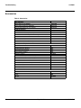
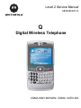
Level 2 Service Manual
6809497A97-O
Q
Digital Wireless Telephone
CDMA 800/1900 MHz, CDMA 1X/EV-DO
MOTOROLA and the Stylized M Logo are registered in the US Patent & Trademark Office.
All other product or service names are the property of their respective owners.
© Motorola, Inc. 2006.
All rights reserved.
Mobile Devices Business,
Sawgrass International Concourse
789 International Parkway
Room S2C
Sunrise, FL 33325-6220
Level 2 Service Manual
2
Contents
Q CDMA
6809497A97-O
Contents
Contents
Introduction . . . . . . . . . . . . . . . . . . . . . . . . . . . . . . . . . . . . . . . . . . . . . . . . . . . . . . . . . . . . . . . . . . . . . . . . . . . . . . 4
Product Identification . . . . . . . . . . . . . . . . . . . . . . . . . . . . . . . . . . . . . . . . . . . . . . . . . . . . . . . . . . . . . . . . 4
Product Names . . . . . . . . . . . . . . . . . . . . . . . . . . . . . . . . . . . . . . . . . . . . . . . . . . . . . . . . . . . . . . . . . . . . . 4
Regulatory Agency Compliance . . . . . . . . . . . . . . . . . . . . . . . . . . . . . . . . . . . . . . . . . . . . . . . . . . . . . . . . 4
Computer Program Copyrights . . . . . . . . . . . . . . . . . . . . . . . . . . . . . . . . . . . . . . . . . . . . . . . . . . . . . . . . 5
About this Service Manual . . . . . . . . . . . . . . . . . . . . . . . . . . . . . . . . . . . . . . . . . . . . . . . . . . . . . . . . . . . . 5
Warranty Service Policy . . . . . . . . . . . . . . . . . . . . . . . . . . . . . . . . . . . . . . . . . . . . . . . . . . . . . . . . . . . . . . 6
Parts Replacement . . . . . . . . . . . . . . . . . . . . . . . . . . . . . . . . . . . . . . . . . . . . . . . . . . . . . . . . . . . . . . . . . . 7
Specifications . . . . . . . . . . . . . . . . . . . . . . . . . . . . . . . . . . . . . . . . . . . . . . . . . . . . . . . . . . . . . . . . . . . . . . . . . . . 8
Product Overview . . . . . . . . . . . . . . . . . . . . . . . . . . . . . . . . . . . . . . . . . . . . . . . . . . . . . . . . . . . . . . . . . . . . . . . . . 9
Features . . . . . . . . . . . . . . . . . . . . . . . . . . . . . . . . . . . . . . . . . . . . . . . . . . . . . . . . . . . . . . . . . . . . . . . . . . . 9
General Operation . . . . . . . . . . . . . . . . . . . . . . . . . . . . . . . . . . . . . . . . . . . . . . . . . . . . . . . . . . . . . . . . . . . . . . . . 11
Controls, Indicators, and Input/Output (I/O) Connectors . . . . . . . . . . . . . . . . . . . . . . . . . . . . . . . . . . 11
Battery Function . . . . . . . . . . . . . . . . . . . . . . . . . . . . . . . . . . . . . . . . . . . . . . . . . . . . . . . . . . . . . . . . . . . 15
Operation . . . . . . . . . . . . . . . . . . . . . . . . . . . . . . . . . . . . . . . . . . . . . . . . . . . . . . . . . . . . . . . . . . . . . . . . . 16
Tools and Test Equipment . . . . . . . . . . . . . . . . . . . . . . . . . . . . . . . . . . . . . . . . . . . . . . . . . . . . . . . . . . . . . . . . . 17
Disassembly . . . . . . . . . . . . . . . . . . . . . . . . . . . . . . . . . . . . . . . . . . . . . . . . . . . . . . . . . . . . . . . . . . . . . . . . . . . . . 18
Removing the Battery Door . . . . . . . . . . . . . . . . . . . . . . . . . . . . . . . . . . . . . . . . . . . . . . . . . . . . . . . . . . 19
Removing and Replacing the Battery . . . . . . . . . . . . . . . . . . . . . . . . . . . . . . . . . . . . . . . . . . . . . . . . . . 20
Removing and Replacing the Rear Housing . . . . . . . . . . . . . . . . . . . . . . . . . . . . . . . . . . . . . . . . . . . . . 21
Removing the Motor/Vibrator Assembly . . . . . . . . . . . . . . . . . . . . . . . . . . . . . . . . . . . . . . . . . . . . . . . . 23
Removing and Replacing the Antenna . . . . . . . . . . . . . . . . . . . . . . . . . . . . . . . . . . . . . . . . . . . . . . . . . 24
Removing the Daughter Board . . . . . . . . . . . . . . . . . . . . . . . . . . . . . . . . . . . . . . . . . . . . . . . . . . . . . . . . 25
Removing the Camera Assembly . . . . . . . . . . . . . . . . . . . . . . . . . . . . . . . . . . . . . . . . . . . . . . . . . . . . . . 26
Removing and Replacing the Speaker Carrier . . . . . . . . . . . . . . . . . . . . . . . . . . . . . . . . . . . . . . . . . . . 27
Removing and Replacing the Main Board . . . . . . . . . . . . . . . . . . . . . . . . . . . . . . . . . . . . . . . . . . . . . . . 28
Removing and Replacing the Keyboard . . . . . . . . . . . . . . . . . . . . . . . . . . . . . . . . . . . . . . . . . . . . . . . . . 30
Removing the Display Assembly . . . . . . . . . . . . . . . . . . . . . . . . . . . . . . . . . . . . . . . . . . . . . . . . . . . . . . 36
Removing and Replacing the Keypad . . . . . . . . . . . . . . . . . . . . . . . . . . . . . . . . . . . . . . . . . . . . . . . . . . 38
Phone Identification . . . . . . . . . . . . . . . . . . . . . . . . . . . . . . . . . . . . . . . . . . . . . . . . . . . . . . . . . . . . . . . . . . . . . . 39
Personality Transfer . . . . . . . . . . . . . . . . . . . . . . . . . . . . . . . . . . . . . . . . . . . . . . . . . . . . . . . . . . . . . . . . 39
Identification . . . . . . . . . . . . . . . . . . . . . . . . . . . . . . . . . . . . . . . . . . . . . . . . . . . . . . . . . . . . . . . . . . . . . . 39
Troubleshooting . . . . . . . . . . . . . . . . . . . . . . . . . . . . . . . . . . . . . . . . . . . . . . . . . . . . . . . . . . . . . . . . . . . . . . . . . 40
Programming: Software Upgrade and Flexing . . . . . . . . . . . . . . . . . . . . . . . . . . . . . . . . . . . . . . . . . . . 41
Exploded View Diagram . . . . . . . . . . . . . . . . . . . . . . . . . . . . . . . . . . . . . . . . . . . . . . . . . . . . . . . . . . . . . 42
Exploded View Parts List . . . . . . . . . . . . . . . . . . . . . . . . . . . . . . . . . . . . . . . . . . . . . . . . . . . . . . . . . . . . 43
Accessories . . . . . . . . . . . . . . . . . . . . . . . . . . . . . . . . . . . . . . . . . . . . . . . . . . . . . . . . . . . . . . . . . . . . . . . . 44
6809497A97-O
May 15, 2006
3
2
Q CDMA
6809501A03-O
Introduction
Q CDMA
Introduction
Motorola® Inc. maintains a worldwide organization that is dedicated to provide
responsive, full-service customer support. Motorola products are serviced by an
international network of company-operated product-care centers as well as
authorized independent service firms.
Available on a contract basis, Motorola Inc. offers comprehensive maintenance and
installation programs that enable customers to meet requirements for reliable,
continuous communications.
To learn more about the wide range of Motorola service programs, contact your local
Motorola products representative or the nearest Customer Service Manager.
Product Identification
Motorola products are identified by the model number on the housing. Use the entire
model number when inquiring about the product. Numbers are also assigned to
chassis and kits. Use these numbers when requesting information or ordering
replacement parts.
Product Names
Product names are listed on the front cover. Product names are subject to change
without notice. Some product names, as well as some frequency bands, are available
only in certain markets.
Regulatory Agency Compliance
This device complies with Part 15 of the FCC Rules. Operation is subject to the
following conditions:
• This device may not cause any harmful interference
• This device must accept interference received, including interference that may
cause undesired operation
This class B device also complies with all requirements of the Canadian
Interference-Causing Equipment Regulations (ICES-003).
Cet appareil numérique de la classe B respecte toutes les exigences du Règlement
sur le matériel brouilleur du Canada.
4
May 15, 2006
6809501A03-O
Level 2 Service Manual
Introduction
Computer Program Copyrights
The Motorola products described in this manual may include Motorola computer
programs stored in semiconductor memories or other media that are copyrighted
with all rights reserved worldwide to Motorola. Laws in the United States and other
countries preserve for Motorola, Inc. certain exclusive rights to the copyrighted
computer programs, including the exclusive right to copy, reproduce, modify,
decompile, disassemble, and reverse-engineer the Motorola computer programs in
any manner or form without Motorola's prior written consent. Furthermore, the
purchase of Motorola products shall not be deemed to grant either directly or by
implication, estoppel, or otherwise, any license or rights under the copyrights,
patents, or patent applications of Motorola, except for a nonexclusive license to use
the Motorola product and the Motorola computer programs with the Motorola
product.
About this Service Manual
Using this service manual and the suggestions contained in it assures proper
installation, operation, and maintenance. Refer questions about this manual to the
nearest Customer Service Manager.
Audience
This service manual aids service personnel in testing and repairing Q telephones.
Service personnel should be familiar with electronic assembly, testing, and
troubleshooting methods, and with the operation and use of associated test
equipment.
Use of this manual assures proper installation, operation, and maintenance of
Motorola products and equipment. It contains all service information required for
the equipment described and is current as of the printing date.
Scope
This manual provides basic information relating to Q telephones, and provides
procedures and processes for repairing the units at Level 1 and 2 service centers
including:
• Unit swap out
• Repairing of mechanical faults
• Basic modular troubleshooting
• Testing and verification of unit functionality
• Initiate warranty claims and send faulty modules to Level 3 or 4 repair
centers
6809501A03-O
May 15, 2006
5
Introduction
Q CDMA
Conventions
The following special characters and typefaces are used in this manual to emphasize
certain types of information.
➧
G
E
H
Note: Emphasizes additional information pertinent to the subject
matter.
Caution: Emphasizes information about actions that may result in
equipment damage.
Warning: Emphasizes information about actions that may result in
personal injury.
Keys to be pressed are represented graphically. For example, instead of “Press
the Menu Key”, you will see “Press H”.
Information from a screen is shown in text as similar as possible to what
displays on the screen. For example, ALERTS.
Information that you need to type is printed in boldface type.
Warranty Service Policy
The product is sold with the standard 12-month warranty terms and conditions.
Accidental damage, misuse, and extended warranties offered by retailers are not
supported under warranty. Non warranty repairs are available at agreed fixed
repair prices.
Out-of-Box Failure Policy
The standard out of box failure criteria applies. Customer units that fail very early
on after the date of sale, are to be returned to Manufacturing for root cause analysis,
to guard against epidemic criteria. Manufacturing will bear the costs of early life
failure.
Product Support
Customer’s original units will be repaired but not refurbished as standard.
Appointed Motorola Service Hubs will perform warranty and non-warranty field
service for level 2 (assemblies) and level 3 (limited PCB component). The Motorola
High Technology Centers will perform level 4 (full component) repairs.
Customer Support
Customer support is available through dedicated Call Centers and in-country help
desks. Product Service training is available through the local Motorola Support
Center.
6
May 15, 2006
6809501A03-O
Level 2 Service Manual
Introduction
Parts Replacement
When ordering replacement parts or equipment, include the Motorola part number
and description used in the service manual or supplement.
When the Motorola part number of a component is not known, use the product model
number or other related major assembly along with a description of the related
major assembly and of the component in question.
In the U.S.A., to contact Motorola, Inc. on your TTY, call: 800-793-7834
Accessories and Aftermarket Division (AAD)
Order replacement parts, test equipment, and manuals from AAD.
U.S.A.
Outside U.S.A.
Phone: 800-422-4210
Phone: 847-538-8023
FAX: 800-622-6210
FAX: 847-576-3023
Website: http://businessonline.motorola.com
EMEA
Phone: +49 461 803 1404
Website: http://emeaonline.motorola.com
Asia
Phone: +65 648 62995
Website: http://asiaonline.motorola.com
6809501A03-O
May 15, 2006
7
Specifications
Q CDMA
Specifications
General Function
Frequency Range 1900 MHz PCS
Frequency Range 800 MHz CDMA
Channel Spacing
Channels
Modulation
Duplex Spacing
Frequency Stability
Power Supply
Average Transmit Current
Average Stand-by Current
Dimensions (WHD)
(with 1130 mAh Li Ion battery)
Size (Volume)
Weight
Temperature Range
Humidity
Battery Life, 1130 mAh Li Ion Battery
Transmitter Function
RF Power Output
Input/Output Impedance
Transmit Audio Response
Modulation
CDMA Transmit Waveform Quality
(Rho)
Receiver Function
Receive Sensitivity
Audio Distortion
Adjacent and Alternate Channel
Desensitization
8
Specification
1931.250 -1988.750 MHz Rx
1851.250 -1908.750 MHz Tx
869.70 - 893.31 Rx
824.70 - 848.31 Tx
50 kHz PCS
30 kHz CDMA
1150 PCS
788 CDMA 800
1M25D1W (1.25 MHz bandwidth) CDMA
3G1XRTT (1.25 MHz bandwidth) CDMA-1X
80 MHz PCS
45 MHz CDMA 800
± 150 Hz (CDMA)
3.6V Li Ion 1130 mAh battery
310 mA at +13 dBm)
3.40 mA
64mm x 116mm x 11.5mm
2.5 in. x 4.5 in. x 0.4 in.
80 cc (4.8 in.3) without antenna
<115g (4.65 oz) with battery
-30° C to +60° C (-22° F to +140° F)
80% Relative Humidity at 50° C (122° F)
Up to 180 minutes digital talk time (IS 95 A/B)
Up to 250 hours (IS 95 A/B) standby time
Up to 350 hours (IS 2000) standby time
All talk and standby times are approximate and
depend on network configuration, signal strength,
and features selected.
Specification
0.20 watts -23 dBm into 50 ohms (CDMA
nominal)
50 ohms (nominal)
6 dBm/octave pre-emphasis
1M25DIW (1.25 MHz bandwidth) CDMA
0.94
Specification
-104 dBm (CDMA, 0.5% Static FER) 0.5% or less
Less than 5% at 1004 Hz, +/- 8 kHz peak
frequency deviation (transmit and receive)
3% BER max at 107 dBm signal; -94 dBm/30 kHz,
-65 dBm/60 kHz
May 15, 2006
6809501A03-O
Level 2 Service Manual
Product Overview
Product Overview
Motorola Q mobile telephones feature Code Division Multiple Access (CDMA)
technology. Q also supports EVDO a wireless radio broadband data standard
adopted by many CDMA mobile phone service providers. Compared to 1xRTT
(CDMA2000 1x) networks currently being used by operators, 1xEV-DO is
significantly faster, providing mobile devices with air interface speeds of up to
2.4576 Mb/s with Rev. 0 and up to 3.1 Mb/s with Rev. A. Only terminals with 1xEVDO chipsets can take advantage of the higher speeds.
The Q uses the Microsoft Windows Mobile operating system. Windows Mobile is a
compact operating system for mobile devices based on the Microsoft Win32 API.
The Q mobile device provides Short Message Service (SMS) text messaging, and
includes clock, alarm, datebook, calculator, and caller profiling personal
management tools. The Q also has a built in 1.3 Megapixel camera with 6X digital
zoom, Bluetooth wireless connectivity. The phone provides 32 Embedded ring tones
including VibraCall vibrating alert and 32 Downloadable/Customizable iMelody
ring tones. The phone also contains a Secure Data (SD) removable memory
expansion slot. The Q is a dual band phone that allows roaming within the CDMA
800 and 1900 MHz bands.
The Q CDMA phone consists of a main housing assembly that contains the battery,
battery cover, accessory connector, main circuit board, chassis, keypad, and internal
antenna. The main display, speaker, control keys, and a QWERTY keyboard are
located on the front of the device. The camera, battery compartment, and rf
connectors are located at the rear of the device.
The main circuit board contains the Receiver, Transmitter, Synthesizer and Control
Logic Circuitry which together comprise the dual band phone electronics.
The main display is a 2.4" 320 x 240 65k TFT LCD. The camera is a 1.3 mega pixel,
with 6X digital zoom.
The telephones are made of polycarbonate plastic. The 1130 mAh Lithium Ion (Li
Ion) battery provides up to 178 minutes of talk time in CDMA mode with up to 141
hours of standby time1.
Features
Q telephones use advanced, self-contained, sealed, custom integrated circuits to
perform the complex functions required for CDMA communication. Aside from the
space and weight advantage, microcircuits enhance basic reliability, simplify
maintenance, and provide a wide variety of operational functions.
Features available in this product include:
•
•
•
•
•
•
•
Thinnest Converged Device on the market – 11.5mm
Windows Mobile™ 5.0 software with email, calendar, contacts and tasks
Enabled for leading corporate email solutions
Receive and view documents, spreadsheets, presentations and more
Optimized QWERTY keyboard
Video capture and playback
Connectivity via ActiveSync®, AirSync®, Bluetooth™ wireless technology and
IrDA
1. All talk and standby times are approximate and depend on network configuration, signal strength, and features selected. Standby
times are quoted as a range from DRX=2 to DRX=9. Talk times are quoted as a range from DTX off to DTX on.
6809501A03-O
May 15, 2006
9
Product Overview
Q CDMA
•
•
•
•
•
•
•
•
•
1.3 mega pixel camera
Multi-Media Messaging (MMS)
Dual stereo quality speakers
Audio formats supported: iMelody, MIDI, MP3, AAC, WAV, WMA, WAX,
QCELP
Image formats supported: GIF87a, GIF89a, JPEG, WBMP, BMP, PNG
Video formats supported: H.263, MPEG-4, GSM-AMR, AAC, WMV
Mini-SD removable memory
Large, high-resolution display (320 x 240 pixels, 65K TFT)
Display: 2.4” 320x240 65K TFT
Personal Information Management
The Q leverages Microsoft’s Windows Mobile software and is among the first devices
to run on the new Windows Mobile 5.0 platform which delivers scalable and costeffective mobile messaging support with Exchange 2003 out of the box.
Enabled for leading corporate email solutions, the Moto Q can meet the diverse
needs of the enterprise.
The user can receive and view documents, spreadsheets, presentations and more.
10
May 15, 2006
6809501A03-O
Level 2 Service Manual
General Operation
General Operation
Controls, Indicators, and Input/Output (I/O) Connectors
The Q telephones’ controls are on the front and sides of the device, and on the
keyboard as shown in Figures 1 and 2.
Navigate menus.
Center Key
Selects menu
items.
Left Soft Key
Right Soft Key
Make & answer
calls.
Turn on & off,
hang up, exit
menus.
Back Key
Enter Key
Home Key
Voice Key
ALT Key
Camera Key
Microphone
Space Key
050250o
Figure 1. Controls and Indicators Locations, Front
6809501A03-O
May 15, 2006
11
General Operation
Q CDMA
Infrared Port
Thumb Wheel
Mini SD
Port
Undo/Back
Key
Charge up and
connect phone
accessories
060151o
Figure 2. Controls and Indicator Locations, Left and Right Side
Headset Jack
Camera Lens
Camera
Flash
Battery Door
Release
Speakers
060xxxo
Figure 3. Controls and Indicator Locations, Back Side
Menu Navigation
Q telephones have a simple icon and GUI. The phone also features a
customizeable Start menu accessed by pressing the Start key.
12
May 15, 2006
6809501A03-O
Level 2 Service Manual
General Operation
A 5-way navigation key allows you to move easily through menus. Figure 4 provides
a view of the Home screen display.
060170o
Figure 4. Home Screen Display
Status Icons
The main display provides constant graphical representations of battery capacity
and signal strength, as well as the real-time clock. The Q user guide provides more
information about icons shown on the main display.
➧
6809501A03-O
Whether a phone displays all indicators depends on the programming and services
to which the user subscribes.
May 15, 2006
13
General Operation
Q CDMA
3. Roam
2. Message
Indicator
4. Active
Line
5. Signal
Strength
Q
C E GH
6. Battery
Level
7. Profile
8. Location
1. Data
o
Figure 5. Home Screen Status Icons
1 Data Indicator Shows connection status. Other indicators can include:
E = Bluetooth® wireless connection
a = secure data transfer
2 Message Indicator Shows when you receive a new message. Indicators can
include:
C
= new e-mail or text message
B = voicemail message
3 Roam Indicator The roam indicator shows when your phone is seeking or using
a network outside your home network. Other indicators can include:
)
= 2G home
+
= roaming unavailable
4 Active Line Indicator Shows T to indicate an active call, or D to indicate when
call forwarding is on. Indicators can include:
H = line 1 active
I = line 2 active
8 = line 1 active, call forward on
9 = line 2 active, call forward on
5 Signal Strength Indicator Vertical bars show the strength of the network
connection. You can’t make or receive calls when 0 or *displays.
14
May 15, 2006
6809501A03-O
Level 2 Service Manual
General Operation
6 Battery Charge Indicator Vertical bars show the battery charge level.
Recharge the battery when your phone shows Low Battery.
7 Profile Indicator Shows the call alert (ring) setting. When the profile is normal,
outdoor, or automatic, no indicator is displayed.
< = meeting
% = speakerphone
& = car
(no icon) = normal
Q = silent
(no icon) = outdoor
& = headset
(no icon) = automatic
8 Location Indicator Shows when your phone can send location information # or
not $.
Battery Function
Battery Charge Indicator
The telephone displays a battery charge indicator icon in the idle screen to indicate
the battery charge level. The gauge shows four levels: 100%, 66%, 33%, and Low
Battery.
Battery Removal
Removing the battery causes the device to shut down immediately and lose any
pending work (partially entered phone book entries or outgoing messages, for
example). If battery is removed before the unit is fully powered down, the display
will not display properly until the unit is powered down correctly and then
repowered up. (Snowy screen).
E
All batteries can cause property damage and/or bodily injury such as burns if a
conductive material, such as jewelry, keys, or beaded chains touch exposed terminals. The conductive material may complete an electrical circuit (short circuit) and
become quite hot. Exercise care in handling any charged battery, particularly when
placing it inside a pocket, purse, or other container with metal objects.
G
If the battery is removed while receiving a message, the message is lost.
➧
6809501A03-O
To ensure proper memory retention, turn the phone OFF before removing the
battery. Immediately replace the old battery with a fresh battery.
May 15, 2006
15
General Operation
Q CDMA
Operation
For detailed operating instructions, refer to the appropriate User Guide listed in
the Related Publications section toward the end of this manual.
16
May 15, 2006
6809501A03-O
Level 2 Service Manual
2
Q CDMA
6809495A97-O
Tools and Test Equipment
Tools and Test Equipment
The following table lists tools and test equipment recommended for disassembly
and reassembly of Q telephones. Use either the listed items or equivalents.
Table 1. General Test Equipment and Tools
Motorola Part Number1
RSX4043-A
Description
Application
Torque Driver
Used to remove and replace screws
Torque Driver Bit T-6, Apex 440-6 Torx or
equivalent. Torque setting is 1.25 in-lbs
or 14 Ncm
Used with torque driver
See Table 7
Rapid Charger
Used to charge battery and power
phone
0180386A82
Antistatic Mat Kit (includes 66-80387A95
antistatic mat, 66-80334B36 ground
cord, and 42-80385A59 wrist band)
Provides protection from damage to
device caused by electrostatic discharge
(ESD)
—
19501980 (AMS)2
Generic Press Tool
0-00-00-40849 (AMS)2
keyboard adapter
Used to install keyboard
0-00-00-30005 (AMS)2
Disassembly tool, plastic with flat and
pointed ends (manual opening tool)
Used during assembly/disassembly of
phone
1. To order in North America, contact Motorola Aftermarket and Accessories Division (AAD) at (800) 422-4210 or
FAX (800) 622-6210; Internationally, AAD can be reached by calling (847) 538-8023 or by fax (847) 576-3023.
2. Not available from Motorola. To order, contact: AMS Software & Elektronik GmbH, c/o Holger Grube, Lise-MeitnerStraße 9 D-24941 Flensburg Tel.: +49-461-90398-0 Fax: +49-461-90398-50
6809495A97-O
May 15, 2006
17
Disassembly
Q CDMA
Disassembly
The procedures in this section provide instructions for the disassembly of a Q
telephone. Tools and equipment used for the phone are listed in Table 1, preceding.
18
G
Many of the integrated devices used in this phone are vulnerable to damage from
electrostatic discharge (ESD). Ensure adequate static protection is in place when
handling, shipping, and servicing the internal components of this equipment.
G
Avoid stressing the plastic in any way to avoid damage to either the plastic or
internal components.
May 15, 2006
6809495A97-O
Level 2 Service Manual
Disassembly
Removing the Battery Door
1.
2.
3.
4.
Ensure the phone is turned off.
Slide the battery cover latch as shown in Figure 6.
Gently lift the top end of the battery cover away from the phone.
Lift the battery cover away from the phone.
Battery door latch
060167o
Figure 6. Removing the Battery Door
5.
6.
7.
6809495A97-O
To replace, align the battery cover to the phone.
Insert the bottom end of the battery cover into the phone.
Lower the top end of the battery cover onto the phone until battery cover latch
snaps into place.
May 15, 2006
19
Disassembly
Q CDMA
Removing and Replacing the Battery
E
All batteries can cause property damage and/or bodily injury, such as burns if a
conductive material, such as jewelry, keys, or beaded chains touch exposed terminals. The conductive material may complete an electrical circuit (short circuit) and
become quite hot. Exercise care in handling any charged battery, particularly when
placing it inside a pocket, purse, or other container with metal objects.
1.
2.
3.
4.
Ensure the phone is turned off.
Remove the battery cover as described in the procedures.
Lift up the edge of the battery near the side of the phone, as shown in Figure 7.
Lift the battery out of the phone.
Battery
060173o
Figure 7. Removing the Battery
5.
6.
7.
8.
20
To replace, align the battery with the battery compartment so the contacts on
the battery match the battery contacts in the phone.
Insert the left edge of the battery into the battery compartment.
Lower the right edge of the battery into the battery compartment until the
battery is completely seated.
Replace the battery door as described in the procedures.
May 15, 2006
6809495A97-O
Level 2 Service Manual
Disassembly
Removing and Replacing the Rear Housing
1.
2.
Remove the battery door, and the battery as described in the procedures.
Use a T-6 driver to remove the four rear housing screws on the back of the
phone (see Figure 8).
Housing screw locations
Housing screw locations
060190o
Figure 8. Removing the Rear Housing Screws
6809495A97-O
May 15, 2006
21
Disassembly
Q CDMA
3.
Insert the disassembly tool between the front and rear housings and rotate it
at the places indicated (as shown in Figure 9) to release the housing snaps.
Press on the front housing and then pull the front and rear housings apart.
3
Rear housing
2
4
1
4
4
Disassembly tool
060195o
Figure 9. Removing the Rear Housing Latches
4.
5.
6.
7.
8.
22
Lift the top end of the rear housing, and then the bottom end away from the
phone.
To replace, align the rear housing to the phone.
Carefully press the rear housing onto the phone until all the housing snaps are
fully engaged.
Insert 6 T6 screws into the rear housing assembly and tighten to 14 Ncm
(1.25 inch-pounds).
Replace the battery and battery door as described in the procedures.
May 15, 2006
6809495A97-O
Level 2 Service Manual
Disassembly
Removing the Motor/Vibrator Assembly
1.
2.
Remove the battery door, battery, and rear housing, as described in the
procedures.
Use the plastic tweezers to lift the motor/vibrator assembly out of the rear
housing (see Figure 10).
Plastic tweezers
Rear housing assembly
Motor/vibrator assembly
060346o
Figure 10. Removing the Motor/Vibrator Assembly
3.
4.
5.
6809495A97-O
To replace, align the motor/vibrator assembly to its place in the rear housing
assembly.
Carefully press the motor/vibrator assembly into position in the rear housing.
Ensure the motor/vibrator shaft turns freely.
Replace the rear housing, battery, and battery door as described in the
procedures.
May 15, 2006
23
Disassembly
Q CDMA
Removing and Replacing the Antenna
1.
2.
3.
Remove the battery cover, battery and rear housing as described in the
procedures.
Insert one prong of the metal tweezers into the access slot to release the snap
securing the antenna carrier to the main PC board.
Once the snap is released, lift the antenna carrier straight up and away from
the phone. Avoid damage to the pogo pins (see Figure 11).
Antenna carrier
Access slot
Snap
060200o
Figure 11. Removing the Antenna Carrier
4.
5.
6.
24
To replace, align the antenna carrier to the phone.
Press the antenna carrier onto the main board until the snaps engage.
Replace the rear housing, battery, and battery cover as described in the
procedures.
May 15, 2006
6809495A97-O
Level 2 Service Manual
Disassembly
Removing the Daughter Board
1.
2.
Remove the battery door, battery, rear housing, and antenna as described in
the procedures.
Insert the disassembly tool under the daughter board and rotate the
disassembly tool to unseat the daughterboard from its connector on the main
PC board (see Figure 9).
Disassembly tool
Daughter board
060213o
Figure 12. Removing the Daughter Board
3.
4.
5.
6809495A97-O
Lift the daughter board away from the phone.
To replace, align the daughter board to the main PC board and then gently
press the daughter board connector to fully seat the connector into the main
board socket.
Replace the antenna, rear housing, battery and battery door as described in
the procedures.
May 15, 2006
25
Disassembly
Q CDMA
Removing the Camera Assembly
1.
G
Remove the battery door, battery, rear housing, antenna, and daughter board
as described in the procedures.
The flexible printed cable (FPC) (flex) is easily damaged. Exercise extreme care when
handling.
2.
Insert the flat end of the disassembly tool under the edge of the camera
connector and rotate the tool to unseat the camera connector from the socket
(see Figure 13),
Camera
connector
060215a
Figure 13. Removing the Camera Assembly Connector
26
May 15, 2006
6809495A97-O
Level 2 Service Manual
Disassembly
Removing and Replacing the Speaker Carrier
1.
2.
3.
Remove the battery door, battery, and rear housing, as described in the
procedures.
Use the disassembly tool to release the latches that secure the speaker.
Lift the speaker carrier up and out of the rear housing (see Figure 14).
Rear housing
Speaker carrier
Latch
Latch
Disassembly tool
060217o
Figure 14. Removing the Speaker Carrier
4.
5.
6809495A97-O
To replace, align the speaker carrier to the rear housing and press into position
so that latches secure the speaker carrier.
Replace the rear housing, battery and battery door as described in the
procedures.
May 15, 2006
27
Disassembly
Q CDMA
Removing and Replacing the Main Board
1.
G
Remove the battery door, battery, rear housing, antenna, and daughter board
as described in the procedures.
The flexible printed cable (FPC) (flex) is easily damaged. Exercise extreme care when
handling.
2.
Use the disassembly tool to unseat the display flex connector (See Figure 15).
Disassembly tool
Flex connector
060250o
Figure 15. Removing the Display FLEX Connector
28
May 15, 2006
6809495A97-O
Level 2 Service Manual
Disassembly
3.
Carefully remove the main board and keyboard out of the front housing.
Main board
Keyboard
Disassembly tool
060252o
Figure 16. Removing the Main Board and Keyboard
G
This product contains static-sensitive devices. Use anti-static handling procedures
to prevent electrostatic discharge (ESD) and component damage.
4.
5.
6.
7.
6809495A97-O
To replace, align the main board and keyboard to the rear housing assembly
and lower it into place on the rear housing.
Press display flex onto transceiver board adhesive.
Press display flex connector onto its socket.
Replace the keyboard stiffener, speaker cover, keypad bezel, antenna, battery,
and battery cover as described in the procedures.
May 15, 2006
29
Disassembly
Q CDMA
Removing and Replacing the Keyboard
1.
2.
Remove the battery door, battery, rear housing, antenna, daughter board, and
main board, and as described in the procedures.
Use the metal tweezers to remove the grounding gasket from the main board
and keyboard (see Figure 17).
Main board
Grounding gasket
Keyboard
060403o
Figure 17. Removing the Grounding Gasket
30
May 15, 2006
6809495A97-O
Level 2 Service Manual
Disassembly
3.
Insert the disassembly tool under the top of keyboard and slowly slide it under
the keyboard. Once it reaches the center of the board, twist until adhesive
detaches. (see Figure 18).
Main board
Keyboard
Disassembly tool
060791o
Figure 18. Removing the Keyboard
G
This product contains static-sensitive devices. Use anti-static handling procedures
to prevent electrostatic discharge (ESD) and component damage.
Keyboard
Disassembly tool
Main board
060792o
Figure 19. Removing the Keyboard
6809495A97-O
May 15, 2006
31
Disassembly
Q CDMA
4.
5.
6.
Remove adhesive from keyboard and main board and clean with isopropyl
alcohol, if any residue remains. Add new adhesives to the keyboard before
reattaching. Alignment and press fixtures must be used for reassembly.
To replace, attach keyboard and bootstrap to main board.
Remove liners from doubled sided adhesive on keyboard and place keyboard
into alignment fixture.
060793o
Figure 20. Keyboard Connector and Main board Connector Socket
32
May 15, 2006
6809495A97-O
Level 2 Service Manual
Disassembly
7.
Attach Bootstrap as shown. Apply “L” shaped adhesive to Main board and align
with the edges of the shield (see Figure 21). Remove the adhesive liner before
attaching to keyboard.
Figure 21. Aligning the Keyboard Adhesive Tape
6809495A97-O
May 15, 2006
33
Disassembly
Q CDMA
8.
Attach the main board to the keyboard using the keyboard assembly fixture
(see Figure 22). Avoid contact with nearby board components.
060794o
Figure 22. Keyboard Assembly Fixture
9.
Press fixture should be set to exert 19 lbf (8,620 gf) at the ram head for 5
seconds. The input pressure can be calculated using the required force & the
area of the pistons; P=F/A.
10. Carefully place PCB assembly into the press fixture. Use the alignment pins
to hold assembly in place.
11. Once PCB assembly is in place, press the 2 buttons on the side of the fixture.
34
May 15, 2006
6809495A97-O
Level 2 Service Manual
Disassembly
12. Apply Main Board to Key Board conductive gasket as shown.
060794o
Figure 23. Keyboard Assembly Fixture
13. Replace the main board, daughter board, antenna, rear housing, battery and
battery door as described in the procedures.
6809495A97-O
May 15, 2006
35
Disassembly
Q CDMA
Removing the Display Assembly
1.
2.
Remove the battery door, battery, rear housing, antenna, daughter board,
camera assembly, speaker carrier, main board, and keyboard as described in
the procedures.
Use the metal tweezers to release the display module catches in the order
shown in Figure 24.
Display catch
2
3
1
Display catch
Display catch
060427o
Figure 24. Removing the Display Assembly Catches
36
May 15, 2006
6809495A97-O
Level 2 Service Manual
Disassembly
3.
Apply a small amount of force to the lower right side of the display assembly
and lift the left side of the display out of the front housing (see Figure 25).
Display Flex
Display assembly
Front housing
060421o
Figure 25. Removing the Display Assembly
G
The flexible printed cable (FPC) (flex) is easily damaged. Exercise extreme care when
handling.
4.
5.
6.
7.
8.
9.
6809495A97-O
Carefully lift the right side of the display assembly out of the front housing.
To replace, align the display assembly to the front housing.
Carefully insert the right side of the display assembly into the front housing.
Carefully lower the left side of the display assembly into the front housing.
Apply slight pressure to all four corners of the display assembly to ensure that
all four display assembly catches are properly engaged.
Replace the keyboard, main board, daughter board, antenna, rear housing,
battery and battery door as described in the procedures.
May 15, 2006
37
Disassembly
Q CDMA
Removing and Replacing the Keypad
1.
2.
Remove the antenna, battery cover, battery, rear housing assembly, flex
connector, transceiver board assembly, and keyboard as described in the
procedures.
Use the metal tweezers to lift the keypad from the front housing as shown in
Figure 26.
Keypad latches
Keypad
Alignment
Hole
060318o
Figure 26. Removing the Keypad
3.
4.
5.
6.
38
To replace, insert the keypad into the front housing. Align the slots at the sides
of the keypad metal supports to the keypad latches in the front housing.
Top tab of keypad should fit underneath the main lens.
Ensure the alignment holes align properly with the alignment pins in the front
housing.
Replace the keyboard, main board, camera assembly, daughter board, antenna,
rear housing assembly, battery, and battery door as described in the
procedures.
May 15, 2006
6809495A97-O
Level 2 Service Manual
Phone Identification
Phone Identification
Personality Transfer
A personality transfer is required when a phone is express exchanged or when the
main board is replaced. Personality transfers reproduce the customer's original
personalized details such as menu and stored memory, such as phone books, or even
just program a unit with basic user information such as language selection.
Identification
Each Motorola CDMA phone is labeled with a variety of identifying numbers.
Figure 27 describes the current identifying labels.
Type approval
information
Mfg by
MOTOROLA INC. FCC ID: IHDT5UV1 EE 3
Transceiver
model
Radio serial no. :
ESN, yr, month of
mfg, warr. code
(Code 39)
D414AF0E8AA
CANADA: 109 182 230A; TYPE:UVKA
832/2412 CHANNEL OPERATION
SWF3001A
H7 25821A2
SN: D414AF0EYAA A56
VY
NAMPS
info. (analog)
Transceiver model
(code 39)
G6 #
Radio SN: ESN+
year, month of
mfg, warranty
code
Factory
designation
APC Code
Board
tracking ID
G6VYY
Week, year, day
& shift, line, cell,
side of
manufacture
020463o
Figure 27. CDMA Telephone Identification Label
6809495A97-O
May 15, 2006
39
Troubleshooting
Q CDMA
Troubleshooting
Table 2. Level 1 and 2 Troubleshooting Chart
Symptom
1. Telephone will not turn on or stay on.
2. Telephone exhibits poor reception or
erratic operation such as calls frequently
dropping or weak or distorted audio.
3. Display is erratic, or provides partial or
no display.
Probable Cause
Verification and Remedy
a) Battery either discharged or
defective.
Measure battery voltage across a 50 ohm (>1
Watt) load. If the battery voltage is <3.25 Vdc,
recharge the battery using the appropriate battery
charger. If the battery will not recharge, replace the
battery. If battery is not at fault, proceed to b.
b) Battery connectors open or
misaligned.
Visually inspect the battery connectors on both the
battery and the telephone. Realign and, if
necessary, either replace the battery or refer to a
Level 3 Service Center for the battery connector
replacement. If battery connectors are not at fault,
proceed to c.
c) Transceiver board defective.
Remove the transceiver board. Substitute a known
good transceiver board and temporarily
reassemble the unit. Press the PWR button; if unit
turns on and stays on, disconnect the dc power
source and reassemble the telephone with the
new transceiver board. Verify that the fault has
been cleared. If the fault has not been cleared then
proceed to d.
d) keyboard assembly failure.
Replace the keyboard assembly. Temporarily
connect a +3.6 Vdc supply to the battery
connectors. Depress the PWR button. If unit turns
on and stays on, disconnect the dc power source
and reassemble with the new keyboard assembly.
a) Antenna assembly defective.
Check to make sure that the antenna pin is
properly connected to the transceiver board
assembly. If connected properly, substitute a
known good antenna. If the fault is still present,
proceed to b.
b) Transceiver board defective.
Replace the transceiver board (refer to 1c). Verify
that the fault has been cleared and reassemble the
unit with the new transceiver board.
a) Connections to or from
transceiver board defective.
Check general condition of flex and flex connector.
If the flex and connector are good, check that the
flex connector is fully connected. If not, check
connector to transceiver board connections. If
faulty connector, replace the transceiver board. If
connector is not at fault, proceed to b.
b) Transceiver board assembly
defective.
Replace the transceiver board (refer to 1c). Verify
that the fault has been cleared and reassemble the
unit with the new transceiver board.
4. Incoming call alert transducer audio
distorted or volume is too low.
Replace the transceiver board (refer to 1c). Verify
Faulty transceiver board assembly. that the fault has been cleared and reassemble the
unit with the new transceiver board.
5. Telephone transmit audio is weak.
(usually indicated by called parties
complaining of difficulty in hearing voice).
a) microphone obstructed by user
while holding the phone
Verify transmit audio quality. If transmit audio
quality is still weak and microphone is not
obstructed, proceed to b.
b) keyboard assembly defective
Replace the keyboard assembly with a know good
keyboard assembly. Verify that the fault is cleared
and reassemble the unit with the new keyboard
assembly. If this does not clear the fault, reinstall
the original keyboard assembly and proceed to c
40
May 15, 2006
6809495A97-O
Level 2 Service Manual
Troubleshooting
Table 2. Level 1 and 2 Troubleshooting Chart (Continued)
Symptom
Probable Cause
Verification and Remedy
c) Transceiver board assembly
defective.
Replace the transceiver board assembly (refer to
1c). Verify that the fault has been cleared and
reassemble the unit with the new transceiver board
assembly.
6. Receive audio from earpiece speaker is a) Earpiece speaker defective.
weak or distorted.
Check speaker connections. If connections are at
fault, replace speaker. If connection is not at fault,
proceed to b.
7. Vibrator feature not functioning.
8. Internal Charger not working.
b) Antenna assembly defective.
Check to make sure the antenna is installed
correctly. If the antenna is installed correctly,
substitute a known good antenna assembly. If this
does not clear the fault, reinstall the original
antenna assembly and proceed to c.
c) Transceiver board assembly
defective.
Replace the transceiver board assembly (refer to
1c). Verify that the fault has been cleared and
reassemble with the new transceiver board
assembly.
Replace the Motor/Vibrator assembly. Verify that
Motor/Vibrator assembly defective. the fault has been cleared and reassemble the unit
with the new Motor/Vibrator assembly.
Faulty charger circuit on
transceiver board assembly.
Test a selection of batteries in the rear pocket of
the desktop charger. Check LED display for the
charging indications. If these are charging
properly, then the internal charger is at fault.
Replace the transceiver board assembly (refer to
1c). Verify that the fault has been cleared and
reassemble the unit with the new transceiver board
assembly.
9. No or weak audio when using headset. a) Headset not fully pushed home. Ensure the headset plug is fully seated in the jack
socket. If fault not cleared, proceed to b.
Replace the transceiver board assembly (refer to
b) Faulty jack socket on transceiver 1c). Verify that the fault has been cleared and
board assembly.
reassemble the unit with the new transceiver board
assembly.
Programming: Software Upgrade and Flexing
Contact your local technical support engineer for information about equipment and
procedures for flashing and flexing.
6809495A97-O
May 15, 2006
41
Troubleshooting
Q CDMA
Exploded View Diagram
25
21
19
36
20
38
16
35
12
2
4
5
7
43
11
23
9
8
37
39
17
18
22
33
32
47
42
14
34
6
45
31
3
15
37
24
46
44
40
40
26
27
29
1
10
13
28
060165o
Figure 28. Exploded View
42
May 15, 2006
6809495A97-O
Level 2 Service Manual
Troubleshooting
Exploded View Parts List
Table 3. Exploded View Parts List
Item
Number
Part Number
Description
Item
Number
Part Number
Description
1
1571191C01
Front Housing painted, Satellite
silver
26
8571830B01
PIFA antenna Bottom
2
3289157Y01
Gasket, Main 2.4 Display
27
1571014D01
CDMA Speaker carrier
3
6171110B01
Main Lens
28
5088317Y01
Loud Speaker -14 X 20
4
3571822B01
Screen, earpiece primary
29
3571269B01
Screen, Loudspeaker
5
3571823B01
Screen, earpiece tertiary
30
6
3871041B01
Side Button, Silver
31
1571337C01
Battery door standard, satellite silver
7
0571010D01
HSJ Grommet, Dark Silver
32
4171793B01
Battery latch spring
8
6171030D01
IRDA Lens
33
5571196C01
Battery door latch, plated
9
1371115B01
Batwing Front
34
4271169D01
Board to board support block
Camera Module -1.3
CDMA receiver camera Grommet
Ear speaker assembly
10
3571294C01
Screen, MIC
35
8471427B01
0571013D01
8490009N03
11
6471043B01
Decorative Bezel
36
0771495C01
8571174B01
8571434C01
CDMA antenna carrier
PIFA antenna Top A
PIFA antenna Top B
12
6471081C01
SAR Shield
37
0387587Y01
Screws (4X)
13
3871040B01
Keypad Assembly, CDMA
38
3871405C01
Screw hole plug, top satellite silver
(2X)
14
1171571C01
Front Liner
39
0571339C01
RF grommet, satellite silver
15
3271378D01
Display side gasket (conductive)
40
3871200C01
Screw hole plug, bottom l, satellite
silver
16
1571012D02
Rear housing painted, Satellite
silver
41
3871199C01
Screw hole plug, bottom r, satellite
silver
17
1371107B01
Batwing Rear
42
7289804Y01
Display -inner module 2.4" TM QVGA
18
8571175B01
Bluetooth Antenna
43
3271826B01
Conductive fabric SAR shield
19
6171112B01
Flash lens
44
3271720C01
Grounding gasket for main board-key
board
20
6187835N02
Lens, Camera, w/Adhesive
45
0171520C01
Main board assembly
21
1371125B01
Camera Bezel CDMA
46
0171518C04
Keyboard assembly
0571153C01
Mini SD Grommet, Satellite
Silver
47
0171521C04
Daughter board assembly
23
8571176B01
GPS antenna
24
3571419B01
Screen, Rear Port
25
0171267C02
Vibrator Motor Assembly
22
6809495A97-O
May 15, 2006
43
Troubleshooting
Q CDMA
Accessories
Table 4. Accessories
Description
Power Solutions
Battery Slim Li Ion (1130mAh)
Battery High Performance (1640mAh)
Travel Charger Rapid U.S. (non-leakage)
In-Vehicle Solutions
Bluetooth Car Kit
Self Install HF Retractable (Razorbill)
Professional Install Car Kit (Junction Box Only)
HUC for PCC
Low Tier VPA Mid rate
VPA Verizon Exclusive Rapid
Vehicle Power Adapter, New ID Rapid
Audio & Connectivity
Paladin Bluetooth Headset
Caller ID Bluetooth Headset
Quadrant Bluetooth Speaker
Qwerty Bluetooth Keyboard
Platform Stereo Headset
FM Stereo Headset
Retractable Headset (new customizable)
One Touch Headset (new customizable)
Mono Headset Black
Mono Headset Silver
Mono Headset (new customizable)
Over the Ear Headset
Neck Loop headset
USB 2.0 Card Reader
Consumer Personalization
Carry Cases
Lanyard
Holster
Belt Clip
44
May 15, 2006
Part Number
SNN5783B
SNN5765A
PSM5202A
S9642
SYN0613
S9950
TBD
SYN9901
SYN0707
SYN9826A
TBD
TBD
TBD
TBD
SYN8609
SYN9050
SYN9351
SYN8390B
AAYN4264A
SYN9350
SYN8908
SYN7875
SYN1045A
TBD
SYN9490A
TBD
SYN8763
6809495A97-O
Level 2 Service Manual
2
Index
Q CDMA
6809497A97-O
Index
A
O
antenna, removing and replacing 24
operation 11
battery 15
controls, indicators, and I/O connectors 11
menu navigation 12
menu structure 15
overview, product 9
B
battery
charge indicator 15
function 15
removing 20
battery cover, removing and replacing 19
P
C
Canadian Interference-Causing Equipment regulations 4
copyrights
computer software 5
D
disassembly 18
display assembly, removing and replacing 36
E
exploded view diagram 42
exploded view parts list 43
F
FCC rules 4
I
identification 39
product 4
Introduction 4
K
Keyboard, removing and replacing 30
keypad
removing 38
keypad, removing and replacing 38
M
Main Board, removing and replacing 28
menu structure 15
motor/vibrator Assembly, removing and replacing 23
N
names
product 4
6809497A97-O
parts
exploded view diagram 42
exploded view parts list 43
product
identification 4
names 4
product overview 9
features 9
R
regulatory agency compliance 4
removing
antenna 24
battery 15, 20
battery cover 19
display assembly 36
Keyboard 30
keypad 38
Main Board 28
motor/vibrator 23
speaker carrier 27
replacement parts
ordering 7
replacing
antenna 24
battery 20
battery cover 19
display assembly 36
Keyboard 30
keypad 38
Main Board 28
motor/vibrator assembly 23
speaker carrier 27
S
service manual
about 5
audience 5
conventions 6
scope 5
May 15, 2006
Index-1
Index
Q CDMA
service policy 6
customer support 6
out of box failure 6
product support 6
shut down
upon battery removal 15
SIM card
personality transfer 39
speaker carrier, removing and replacing 27
specifications 8
support
customer 6
product 6
T
tools and test equipment 17
W
warranty service 6
Index-2
May 15, 2006
6809497A97-O