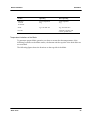
1
ATCA−S100
Reference Guide
P/N 228597 Revision AA
April 2006
Copyright
ECopyright 2006 Motorola GmbH
All rights reserved.
Motorola and the stylized M logo are trademarks of Motorola,Inc., registered in the U.S. Patent and
Trademark Office.
All other product or service names mentioned in this document are the property of their respective
owners.
Notice
While reasonable efforts have been made to assure the accuracy of this document, Motorola GmbH
assumes no liability resulting from any ommissions in this document, or from the use of the information
obtained herein. Motorola reserves the right to revise this document and to make changes from time to
time in the content hereof without obligation of Motorola to notify any person of such revision or changes.
Electronic versions of this material may be read online, downloaded for personal use, or referenced in
another document as a URL to the Motorola Embedded Communications Computing Web site. The text
itself may not be published commercially in print or electronic form, edited, translated, or otherwise
altered without the permission of Motorola GmbH.
It is possible that this publication may contain reference to or information about Motorola products
(machines and programs), programming, or services that are not available in your country. Such
references or information must not be construed to mean that Motorola intends to announce such
Motorola products, programming, or services in your country.
2
ATCA−S100
Contents
Using This Guide
Other Sources of Information
Safety Notes
Sicherheitshinweise
1
Introduction
Features . . . . . . . . . . . . . . . . . . . . . . . . . . . . . . . . . . . . . . . . . . . . . . . . . . . . . . . . . . . . . . . . 21
Standard Compliances . . . . . . . . . . . . . . . . . . . . . . . . . . . . . . . . . . . . . . . . . . . . . . . . . . . 22
Ordering Information . . . . . . . . . . . . . . . . . . . . . . . . . . . . . . . . . . . . . . . . . . . . . . . . . . . . 23
Product Nomenclature . . . . . . . . . . . . . . . . . . . . . . . . . . . . . . . . . . . . . . . . . . . . . . . . . . . . . . . . . . . . . . . . . . . . 23
Order Numbers . . . . . . . . . . . . . . . . . . . . . . . . . . . . . . . . . . . . . . . . . . . . . . . . . . . . . . . . . . . . . . . . . . . . . . . . . . . 23
Feedback . . . . . . . . . . . . . . . . . . . . . . . . . . . . . . . . . . . . . . . . . . . . . . . . . . . . . . . . . . . . . . . 25
2
Installation
Introduction . . . . . . . . . . . . . . . . . . . . . . . . . . . . . . . . . . . . . . . . . . . . . . . . . . . . . . . . . . . . . 27
Before Installation . . . . . . . . . . . . . . . . . . . . . . . . . . . . . . . . . . . . . . . . . . . . . . . . . . . . . . . 28
Requirements . . . . . . . . . . . . . . . . . . . . . . . . . . . . . . . . . . . . . . . . . . . . . . . . . . . . . . . . . . . . . . . . . . . . . . . . . . . .
Environmental Requirements . . . . . . . . . . . . . . . . . . . . . . . . . . . . . . . . . . . . . . . . . . . . . . . . . . . . . . . . . . . .
Power Requirements . . . . . . . . . . . . . . . . . . . . . . . . . . . . . . . . . . . . . . . . . . . . . . . . . . . . . . . . . . . . . . . . . . .
Required Equipment . . . . . . . . . . . . . . . . . . . . . . . . . . . . . . . . . . . . . . . . . . . . . . . . . . . . . . . . . . . . . . . . . . .
Unpacking and Inspecting the Blade . . . . . . . . . . . . . . . . . . . . . . . . . . . . . . . . . . . . . . . . . . . . . . . . . . . . . . . .
28
28
32
33
33
Blade Installation and Power−Up . . . . . . . . . . . . . . . . . . . . . . . . . . . . . . . . . . . . . . . . . 34
Installation in a Powered Shelf . . . . . . . . . . . . . . . . . . . . . . . . . . . . . . . . . . . . . . . . . . . . . . . . . . . . . . . . . . . . . 34
Installation in a Non−Powered Shelf . . . . . . . . . . . . . . . . . . . . . . . . . . . . . . . . . . . . . . . . . . . . . . . . . . . . . . . . . 36
Operation . . . . . . . . . . . . . . . . . . . . . . . . . . . . . . . . . . . . . . . . . . . . . . . . . . . . . . . . . . . . . . . 37
Enabling/Disabling SFPs . . . . . . . . . . . . . . . . . . . . . . . . . . . . . . . . . . . . . . . . . . . . . . . . . . . . . . . . . . . . . . . . . . 37
ATCA−S100
3
Fiber Channel Speed . . . . . . . . . . . . . . . . . . . . . . . . . . . . . . . . . . . . . . . . . . . . . . . . . . . . . . . . . . . . . . . . . . . . . 38
3
Functional Description
Introduction . . . . . . . . . . . . . . . . . . . . . . . . . . . . . . . . . . . . . . . . . . . . . . . . . . . . . . . . . . . . . 40
Function Blocks . . . . . . . . . . . . . . . . . . . . . . . . . . . . . . . . . . . . . . . . . . . . . . . . . . . . . . . . . 41
Hard Disks . . . . . . . . . . . . . . . . . . . . . . . . . . . . . . . . . . . . . . . . . . . . . . . . . . . . . . . . . . . . . . . . . . . . . . . . . . . . . . .
IPMC Storage Blade Management . . . . . . . . . . . . . . . . . . . . . . . . . . . . . . . . . . . . . . . . . . . . . . . . . . . . . . . . . .
Power Supply . . . . . . . . . . . . . . . . . . . . . . . . . . . . . . . . . . . . . . . . . . . . . . . . . . . . . . . . . . . . . . . . . . . . . . . . . . . .
Fiber Channel Connections . . . . . . . . . . . . . . . . . . . . . . . . . . . . . . . . . . . . . . . . . . . . . . . . . . . . . . . . . . . . . . . .
Temperature Sensors . . . . . . . . . . . . . . . . . . . . . . . . . . . . . . . . . . . . . . . . . . . . . . . . . . . . . . . . . . . . . . . . . . . . .
4
42
42
42
42
43
Controls, Indicators, and Connectors
Face Plate . . . . . . . . . . . . . . . . . . . . . . . . . . . . . . . . . . . . . . . . . . . . . . . . . . . . . . . . . . . . . . 45
LEDs . . . . . . . . . . . . . . . . . . . . . . . . . . . . . . . . . . . . . . . . . . . . . . . . . . . . . . . . . . . . . . . . . . . . . . . . . . . . . . . . . . . . 46
FC Connectors . . . . . . . . . . . . . . . . . . . . . . . . . . . . . . . . . . . . . . . . . . . . . . . . . . . . . . . . . . . . . . . . . . . . . . . . . . . 46
Backplane Connectors . . . . . . . . . . . . . . . . . . . . . . . . . . . . . . . . . . . . . . . . . . . . . . . . . . . 47
Zone 2 Connectors . . . . . . . . . . . . . . . . . . . . . . . . . . . . . . . . . . . . . . . . . . . . . . . . . . . . . . . . . . . . . . . . . . . . . . . 47
Power Connector . . . . . . . . . . . . . . . . . . . . . . . . . . . . . . . . . . . . . . . . . . . . . . . . . . . . . . . . . . . . . . . . . . . . . . . . . 48
Sensors . . . . . . . . . . . . . . . . . . . . . . . . . . . . . . . . . . . . . . . . . . . . . . . . . . . . . . . . . . . . . . . . 49
Index
4
ATCA−S100
Tables
Introduction
Tablei1aaaaaaaStandard Compliances . . . . . . . . . . . . . . . . . . . . . . . . . . . . . . . . . . . . . . . . . . . . . . . . . . . . . . . . . . . .
Tablei2aaaaaaaProduct Nomenclature ATCA−S100/xxx−y . . . . . . . . . . . . . . . . . . . . . . . . . . . . . . . . . . . . . . . . . . .
Tablei3aaaaaaaOrdering Information Excerpt . . . . . . . . . . . . . . . . . . . . . . . . . . . . . . . . . . . . . . . . . . . . . . . . . . . . . .
Tablei4aaaaaaaAdditional Ordering Information . . . . . . . . . . . . . . . . . . . . . . . . . . . . . . . . . . . . . . . . . . . . . . . . . . . .
22
23
23
24
Installation
Tablei5aaaaaaaEnvironmental Requirements . . . . . . . . . . . . . . . . . . . . . . . . . . . . . . . . . . . . . . . . . . . . . . . . . . . . . .
Tablei6aaaaaaaDC System Power Requirements . . . . . . . . . . . . . . . . . . . . . . . . . . . . . . . . . . . . . . . . . . . . . . . . . .
Tablei7aaaaaaaMotorola OEM IPMI Commands − Parameters . . . . . . . . . . . . . . . . . . . . . . . . . . . . . . . . . . . . . . .
Tablei8aaaaaaaMotorola OEM IPMI Commands − Request and Response Data Format . . . . . . . . . . . . . . . . .
28
32
37
37
Controls, Indicators, and Connectors
Tablei9aaaaaaaDescription of Face Plate LEDs . . . . . . . . . . . . . . . . . . . . . . . . . . . . . . . . . . . . . . . . . . . . . . . . . . . . 46
Tablei10aaaaaaP23 Connector Pinouts . . . . . . . . . . . . . . . . . . . . . . . . . . . . . . . . . . . . . . . . . . . . . . . . . . . . . . . . . . . 47
Tablei11aaaaaaATCA−S100 Specific Sensors . . . . . . . . . . . . . . . . . . . . . . . . . . . . . . . . . . . . . . . . . . . . . . . . . . . . . . 49
ATCA−S100
5
Figures
Installation
Figurei1aaaaaaaTop Side of the Blade . . . . . . . . . . . . . . . . . . . . . . . . . . . . . . . . . . . . . . . . . . . . . . . . . . . . . . . . . . . . 30
Figurei2aaaaaaaBottom Side of the Hard Disk . . . . . . . . . . . . . . . . . . . . . . . . . . . . . . . . . . . . . . . . . . . . . . . . . . . . . 31
Figurei3aaaaaaaTop Side of the Hard Disk . . . . . . . . . . . . . . . . . . . . . . . . . . . . . . . . . . . . . . . . . . . . . . . . . . . . . . . . 31
Functional Description
Figurei4aaaaaaaFunction Blocks of ATCA−S100 . . . . . . . . . . . . . . . . . . . . . . . . . . . . . . . . . . . . . . . . . . . . . . . . . . . 41
Figurei5aaaaaaaFiber Channel Connections . . . . . . . . . . . . . . . . . . . . . . . . . . . . . . . . . . . . . . . . . . . . . . . . . . . . . . . 43
Controls, Indicators, and Connectors
Figurei6aaaaaaaFace Plate . . . . . . . . . . . . . . . . . . . . . . . . . . . . . . . . . . . . . . . . . . . . . . . . . . . . . . . . . . . . . . . . . . . . . 45
6
ATCA−S100
Using This Guide
This manual is intended for users qualified in electronics or electrical engineering. Users
must have a working understanding of AdvancedTCA and telecommunications.
Conventions
Notation
Description
57
All numbers are decimal numbers except when used with
the notations described below.
Bold
Used to emphasize a word
No danger encountered. Pay attention to important
information
Possibly dangerous situation: slight injuries to people or
damage to objects possible
Abbreviations
Abbreviation
Description
A
A
AdvancedTCA
ATCA
Advanced Telecommunications Computing Architecture
Advanced Telecommunications Computing Architecture
B
B
BIB
Board Information Block
C
C
CGL
CMD
CO
Carrier Grade Linux
Command Code
Central Office
D
D
DC
Direct Current
E
E
EEPROM
Electrically Erasable Programmable Read−Only Memory
ATCA−S100
7
8
Abbreviation
EMC
Description
Electromagnetic Compatibility
EMV
Elektromagnetische Vertraeglichkeit
EN
European Norm
ESD
Electrostatic Sensitive Device
F
F
FC
FCC
Fibre Channel
Federal Communications Commission
FRU
Field Replacable Unit
G
G
GmbH
Gesellschaft mit beschraenkter Haftung
H
H
H/S
HA
Hot−Swap
High Availability
HAF
High Availability Framework
HBA
Host Bus Adapter
HCA
Host Channel Adapter
HDD
Hard Disk Drive
I
I
ID
IEC
Identifier
International Electric Code
IMC
IPM Master Controller
IPM
Intelligent Platform Management
IPMB
Intelligent Platform Management Bus
IPMC
Intelligent Platform Management Controller
IPMI
Intelligent Platform Management Interface
ISC
IPM Slave Controller
L
L
LED
LUN
Light Emitting Diode
Logical Unit Number
M
M
MD
Multiple Device
N
N
NEBS
NetFn
Network Equipment Building System
Network Function Code
NFS
Network File System
O
O
OEM
Original Equipment Manufacturer
ATCA−S100
Abbreviation
OOS
Description
Out−Of−Service
P
P
PBC
PEM
PICMG
PMC
PMC
Port Bypass Circuit
Power Entry Module
PCI Industrial Computer Manufacturers Group
PCI Mezzanine Card
Periperal Management Controller
R
R
RAID
Redundant Array of Inexpensive Disks
S
S
S.M.A.R.T.
SCSI
SDR
SELV
SFP
ShM
ShMC
STB
Software Maintenance and Reference Tool
Small Computer System Interface
Sensor Data Record
Safety Extra Low Voltages
Small Form−Factor Pluggable
Shelf Manager
Shelf Management Controller
Storage Blade
T
T
TNV
TNV−2
Telecommunication Network Voltage
Telecom Network Voltages without overvoltage
U
U
UL
Underwriters Laboratory Inc.
V
V
VCCI
Voluntary Control Council for Interference
ATCA−S100
9
Revision History
Order No.
Rev.
Date
Description
221746
AA
October 2003
Preliminary Installation Guide
Initial Version
AB
December
2003
Changed product name from ATCA FC Storage Blade to
ATCA−S100; Changed Function Blocks figure; Added standard
compliances; Added ordering information; Added environmental
requirements; Changed power requirements; Due to PBC routing
instead of multiplexer routing and changed routing destinations:
Changed figures in Storage Systems Chapter, Changes in Board
Installation, Changes in Zone 2 Connectors. Due to IPMC
changes: Changed switch settings and deleted first step in
installation procedure in Blade Installation; Due to changed face
plate: Note deleted in LEDs; Editorial changes
February 2004
Changed Ordering Information, Changed figure of Fibre Channel
Connections, Changed power requirements.
AC
May 2004
Added storage blade management. Changed backplane
connectors.
AD
August 2004
Added functional description. Completion of the installation
chapter.
AE
September
2004
Updated safety Information and sensor information
AF
December
2004
Updated safety information, figures (overview and face plate)
and requirements.
AG
December
2004
Updated safety information, requirements and inserted
temperature dependencies.
AH
January 2005
Updated temperature dependencies.
AI
February 2005
Updated safety notes and temperature dependencies.
AA
April 2005
Changed logo, copyright, ... from Force Computers to Motorola
AB
May 2005
Added operating voltage for US and Canada. Changed section
"Feedback".
AA
April 2006
Deleted all information on support of fibre channel via backplane
Updated ordering information
226058
228597
10
ATCA−S100
Other Sources of Information
Check the former Force Computers S.M.A.R.T server (http://splus.forcecomputers.com/)
or the Motorola literature catalog for errata sheets that may be applicable to the blade For
further information refer to:
Company
Internet Address
Document
Motorola
www.splus.forcecomputers.co
m
or
www.motorola.com/compute
r/literature
Centellis CO 31kX System Installation Guide
Centellis CO 31kX System Description
ATCA−M100 Installation Guide
AdvancedTCA Shelf Management Interface
Reference Guide
ATCA−S100: Control via IPMI Reference Guide
ACC/ATCA−S100 Installation Guide
PICMG
picmg.org
PICMG 3.0 R 1.0, December 30, 2002
aa
aa
PICMG 3.1 R 1.0, January 22, 2003a
ATCA−S100
11
Safety Notes
This section provides safety precautions to follow when installing, operating, and
maintaining the product.
We intend to provide all necessary information to install and handle the product in this
manual. However, as the product is complex and its usage manifold, we do not guarantee
that the given information is complete. If you need additional information, ask your
Motorola representative.
The product has been designed to meet the standard industrial safety requirements. It
must not be used except in its specific area of office telecommunication industry and
industrial control.
Only personnel trained by Motorola or persons qualified in electronics or electrical
engineering are authorized to install, remove or maintain the product. The information
given in this manual is meant to complete the knowledge of a specialist and must not
be taken as replacement for qualified personnel.
EMC
The blade has been tested in a Standard Motorola system and found to comply with
the limits for a Class A digital device in this system, pursuant to part 15 of the FCC
Rules respectively EN 55022 Class A. These limits are designed to provide reasonable
protection against harmful interference when the system is operated in a commercial
environment.
The blade generates and uses radio frequency energy and, if not installed properly and
used in accordance with this Reference Guide, may cause harmful interference to radio
communications. Operating the system in a residential area is likely to cause harmful
interference, in which case the user will be required to correct the interference at his
own expense.
To ensure proper EMC shielding, always operate the blade with the PMC card
installed. If blades are integrated into open systems, always cover empty slots.
To ensure proper EMC shielding, always operate the blade with the filler blades or
with PMC module installed. If blades are integrated into open systems, always cover
empty slots.
Blade Installation
Observe the following general safety note when installing the blade into your system:
S
12
Restricted access area − The system is only to be installed in a restricted access area.
ATCA−S100
Electrostatic discharge and incorrect blade installation and removal can damage
circuits or shorten their life. Therefore:
S
Touching the blade or electronic components in a non−ESD protected environment
causes component and blade damage. Before touching blade or electronic
components, make sure that you are working in an ESD−safe environment.
S
When plugging the blade in or removing it, do not press or pull on the face plate
but use the handles.
S
Before installing or removing an additional device or module, read the respective
documentation.
S
If the blade is delivered as part of a system, do not change the cabling of the blade
unless it is explicitly stated in the system’s documentation.
Installation
Data loss
Removing the blade with the blue LED still blinking causes data loss.
Wait until the blue LED is permanently illuminated, before removing the blade.
Damage of Circuits
Electrostatic discharge and incorrect blade installation and removal can damage circuits
or shorten their life.
Before touching the blade or electronic components, make sure that you are working in
an ESD−safe environment.
Blade Malfunctioning
Incorrect blade installation and removal can result in blade malfunctioning.
Make sure that the blade is connected to the system backplane via all assembled
connectors and that power is available on all zone 1 power pins.
Blade Malfunctioning
Incorrect blade installation and removal can result in blade malfunctioning.
When plugging the blade in or removing it, do not press on the face plate but use the
handles.
Operation
Blade damage
Blade surface
High humidity and condensation on the blade surface causes short circuits.
Do not operate the blade outside the specified environmental limits. Make sure the
blade is completely dry and there is no moisture on any surface before applying power.
Do not operate the blade below 0°C.
ATCA−S100
13
Blade Overheating and Blade Damage
Operating the blade without forced air cooling may lead to blade overheating and thus
blade damage.
When operating the blade, make sure that forced air cooling is available in the shelf.
Injuries or short circuits
Blade or power supply
In case the ORing diodes of the blade fail, the blade may trigger a short circuit between
input line A and input line B so that line A remains powered even if it is disconnected
from the power supply circuit (and vice versa).
To avoid damage or injuries, always check that there is no more voltage on the line that
has been disconnected before continuing your work.
Hot Swap
Installing the blade into or removing it from a powered system not supporting hot
swap or high availability causes blade damage and data loss. Therefore, only install it
in or remove it from a powered system if the system itself supports hot swap or high
availability and if the system documentation explicitly includes guidelines.
Removing the blade from the backplane while the hot−swap LED is still off causes
data loss. Therefore, wait until the blue hot−swap LED is on before removing the
blade.
Replacement/Expansion
Only replace or expand components or system parts with those recommended by
Motorola. Otherwise, you are fully responsible for the impact on EMC or any possible
malfunction of the product.
Check the total power consumption of all components installed (see the technical
specification of the respective components). Ensure that any individual output current
of any source stays within its acceptable limits (see the technical specification of the
respective source).
Replacement/Expansion
Only replace or expand components or system parts with those recommended by
Motorola. Otherwise, you are fully responsible for the impact on EMC or any possible
malfunction of the product.
As the blade is current protected, an overcurrent results in a power−down of the blade
if an overcurrent occurs. Make sure that the max. power consumption per PMC slot at
+/−12V, 5V and 3.3V level does not exceed 7.5W (total overall used voltages).
14
ATCA−S100
Check the total power consumption of all components installed (see the technical
specification of the respective components). Ensure that any individual output current
of any source stays within its acceptable limits (see the technical specification of the
respective source).
Laser
Some variants of the blade are a Class I laser product. The use of controls or
adjustments or performance of procedures other than those specified herein may result
in hazardous radiation exposure.
Environment
Always dispose of used batteries and/or old blades according to your country’s
legislation, if possible in an environmentally acceptable way.
ATCA−S100
15
Sicherheitshinweise
Dieser Abschnitt enthält Sicherheitshinweise, die bei Einbau, Betrieb und Wartung des
Blades zu beachten sind.
Wir sind darauf bedacht, alle notwendigen Informationen, die für die Installation und den
Betrieb erforderlich sind, in diesem Handbuch bereit zu stellen. Da es sich jedoch bei dem
Board um ein komplexes Produkt mit vielfältigen Einsatzmöglichkeiten handelt, können
wir die Vollständigkeit der im Handbuch enthaltenen Informationen nicht garantieren.
Falls Sie weitere Informationen benötigen sollten, wenden Sie sich bitte an die für Sie
zuständige Geschäftsstelle von Motorola.
Das Blade erfüllt die für die Industrie geforderten Sicherheitsvorschriften und darf
ausschliesslich für Anwendungen in der Telekommunikationsindustrie und im
Zusammenhang mit Industriesteuerungen verwendet werden.
Einbau, Wartung und Betrieb dürfen nur von durch Motorola ausgebildetem oder im
Bereich Elektronik oder Elektrotechnik qualifiziertem Personal durchgeführt werden.
Die in diesem Handbuch enthaltenen Informationen dienen ausschliesslich dazu, das
Wissen von Fachpersonal zu ergänzen, können es aber in keinem Fall ersetzen.
EMV
Das Blade wurde in einem Motorola Standardsystem getestet. Es erfüllt die für digitale
Geräte der Klasse A gültigen Grenzwerte in einem solchen System gemäß den
FCC−Richtlinien Abschnitt 15 bzw. EN 55022 Klasse A. Diese Grenzwerte sollen einen
angemessenen Schutz vor Störstrahlung beim Betrieb des Blades in Gewerbe− sowie
Industriegebieten gewährleisten.
Das Blade arbeitet im Hochfrequenzbereich und erzeugt Störstrahlung. Bei
unsachgemäßem Einbau und anderem als in diesem Handbuch beschriebenen Betrieb
können Störungen im Hochfrequenzbereich auftreten.
Warnung! Dies ist eine Einrichtung der Klasse A. Diese Einrichtung kann im
Wohnbereich Funkstörungen verursachen. In diesem Fall kann vom Betreiber verlangt
werden, angemessene Maßnahmen durchzuführen.
Wenn Sie das Blade in Systeme einbauen, schirmen Sie freie Steckplätze mit einer
Blende ab.
Blade Installation
Bevor Sie die Blade in einem System installieren, überprüfen Sie, ob die im Kapitel
"Installation" aufgeführten Anforderungen erfüllt werden.
16
ATCA−S100
Beachten Sie folgenden allgemeinen Sicherheitshinweis bei der Installation der Blade:
S
Bereich mit eingeschränktem Zugang − Installieren Sie die Blade in ein System nur
in Bereichen mit eingeschränktem Zugang.
Installation
Elektrostatische Entladung und unsachgemäßer Ein− und Ausbau des Blades kann
Schaltkreise beschädigen oder ihre Lebensdauer verkürzen. Beachten Sie deshalb die
folgenden Punkte:
S
Berühren Sie das Blade oder elektrische Komponenten in einem nicht
ESD−geschützten Bereich, kann dies zu einer Beschädigung des Blades führen.
Bevor Sie Boards oder elektronische Komponenten berühren, vergewissern Sie
sich, dass Sie in einem ESD−geschützten Bereich arbeiten.
S
Drücken Sie beim Ein− oder Ausbau des Blades nicht auf die Frontplatte, sondern
benutzen Sie die Griffe.
S
Lesen Sie vor dem Ein− oder Ausbau von zusätzlichen Geräten oder Modulen das
dazugehörige Benutzerhandbuch.
S
Falls das Blade als Teil eines Systems ausgeliefert wird, tauschen Sie keine
Verkabelungen des Blades aus, es sei denn, es ist in der Systemdokumentation
ausdrücklich erwähnt.
Betrieb
Beschädigung des Blades
Hohe Luftfeuchtigkeit und Kondensat auf der Oberfläche des Blades können zu
Kurzschlüssen führen.
Betreiben Sie das Blade nur innerhalb der angegebenen Grenzwerte für die relative
Luftfeuchtigkeit und Temperatur. Stellen Sie vor dem Einschalten des Stroms sicher,
dass sich auf dem Blade kein Kondensat befindet und betreiben Sie das Blade nicht
unter 0°C.
Überhitzung und Beschädigung des Blades
Betreiben Sie das Blade ohne Zwangsbelüftung, kann das Blade überhitzt und
schließlich beschädigt werden.
Bevor Sie das Blade betreiben, müssen Sie sicher stellen, dass das Shelf über eine
Zwangskühlung verfügt.
ATCA−S100
17
Verletzungen oder Kurzschlüsse
Blade oder Stromversorgung
Falls die ORing Dioden des Blades durchbrennen, kann das Blade einen Kurzschluss
zwischen den Eingangsleitungen A und B verursachen. In diesem Fall ist Leitung A
immer noch unter Spannung, auch wenn sie vom Versorgungskreislauf getrennt ist
(und umgekehrt).
Prüfen Sie deshalb immer, ob die Leitung spannungsfrei ist, bevor Sie Ihre Arbeit
fortsetzen, um Schäden oder Verletzungen zu vermeiden.
Hot Swap
Wenn Sie das Blade im laufenden Betrieb in ein System, das weder Hot Swap noch
High Availability unterstützt, installieren bzw. herausziehen, wird das Blade
beschädigt und es gehen Daten verloren. Installieren/entfernen Sie das Blade nur im
laufenden Betrieb, wenn das System Hot Swap oder High−Availability unterstützt und
wenn die Systembeschreibung dies ausdrücklich erlaubt.
Ziehen Sie das Blade im laufenden Betrieb heraus, obwohl die Hot−Swap LED noch
nicht leuchtet, führt das zu Datenverlust. Warten Sie deshalb bis die Hot−Swap LED
blau leuchtet, bevor Sie das Blade herausziehen.
Austausch/Erweiterung
Verwenden Sie bei Austausch oder Erweiterung nur von Motorola empfohlene
Komponenten und Systemteile. Andernfalls sind Sie für mögliche Auswirkungen auf
EMV oder Fehlfunktionen des Produktes voll verantwortlich.
Überprüfen Sie die gesamte aufgenomme Leistung aller eingebauten Komponenten
(siehe die technischen Daten der entsprechenden Komponente). Stellen Sie sicher, dass
die Stromaufnahme jedes Verbrauchers innerhalb der zulässigen Grenzwerte liegt
(siehe die technischen Daten des entsprechenden Verbrauchers).
Austausch/Erweiterung
Verwenden Sie bei Austausch oder Erweiterung nur von Motorola empfohlene
Komponenten und Systemteile. Andernfalls sind Sie für mögliche Auswirkungen auf
EMV oder Fehlfunktionen des Produktes voll verantwortlich.
Das Blade ist gegen Überstrom gesichert und schaltet bei einem Überstrom ab. Stellen
Sie sicher, dass der Gesamtstromverbrauch pro PMC Modul bei +/− 12V, 5V und 3,3V
7,5W nicht übersteigt (Summe aller Spannungen).
Überprüfen Sie die gesamte aufgenomme Leistung aller eingebauten Komponenten
(siehe die technischen Daten der entsprechenden Komponente). Stellen Sie sicher, dass
18
ATCA−S100
die Stromaufnahme jedes Verbrauchers innerhalb der zulässigen Grenzwerte liegt
(siehe die technischen Daten des entsprechenden Verbrauchers).
Laser
Einige Varianten des Produktes sind Laserprodukte der Klasse I. Um nicht schädlicher
Laserstrahlung ausgesetzt zu werden, beachten Sie die folgenden Hinweise:
Anpassungen am Produkt, die Bedienung von Steuerelementen sowie die
Durchführung von Prozeduren dürfen nur gemäß den Anweisungen in diesem
Dokumnent erfolgen.a
Umweltschutz
Entsorgen Sie alte Batterien und/oder Blades stets gemäß der in Ihrem Land gültigen
Gesetzgebung, wenn möglich immer umweltfreundlich.
ATCA−S100
19
1
Introduction
Features . . . . . . . . . . . . . . . . . . . . . . . . . . . . . . . . . . . . . . . . . . . . . . . . . . . . . . . . . . . . . . . . 21
Standard Compliances . . . . . . . . . . . . . . . . . . . . . . . . . . . . . . . . . . . . . . . . . . . . . . . . . . . 22
Ordering Information . . . . . . . . . . . . . . . . . . . . . . . . . . . . . . . . . . . . . . . . . . . . . . . . . . . . 23
Product Nomenclature . . . . . . . . . . . . . . . . . . . . . . . . . . . . . . . . . . . . . . . . . . . . . . . . . . . . . . . . . . . . . . . . . . . . 23
Order Numbers . . . . . . . . . . . . . . . . . . . . . . . . . . . . . . . . . . . . . . . . . . . . . . . . . . . . . . . . . . . . . . . . . . . . . . . . . . . 23
Feedback . . . . . . . . . . . . . . . . . . . . . . . . . . . . . . . . . . . . . . . . . . . . . . . . . . . . . . . . . . . . . . . 25
20
ATCA−S100
Features
Introduction
Features
ATCA−S100 is an Advanced Telecom Computing Architecture (AdvancedTCA) PICMG
3.0 and PICMG 3.1 compliant single−slot mass storage module with up to 300 GByte Hard
Disk Drive (HDD) storage capacity. It is designed for use in systems which meet the
AdvancedTCA specification.a
Important features are:
S
Two 3.5−inch Fibre Channel (FC) HDDs for on−board storage
S
Face plate connection via Small Form Pluggable (SFP) connectors enables mass storage
expansion
S
Redundant FC connectivity available on face plate provides scalable blade
architectures
S
1 or 2 Gbit/s FC interfaces
S
Supports FC switch architectures as well as direct Host Bus Adapter (HBA)
S
Hardware Management by AdvancedTCA compliant Intelligent Platform
Management Interface Controller (IPM Controller/IPMC)
S
Hot−swappable ATCA−S100 blade ensures serviceability and system availability
The ATCA−S100 storage blade is built for face plate connection and has a wide field of
application. A sophisticated application is a High Availability (HA) storage solution
which includes the necessary software components to use the blades in a redundant
configuration so that if one blade is removed no data will be lost to the system.a
ATCA−S100
21
Introduction
Standard Compliances
Standard Compliances
ATCA−S100 meets the following standards:a
Table 1: Standard Compliances
Standarda
Description
UL 60950−1, EN 60950−1, IEC 60950−1 CAN/CSA
C22.2 No 60950−1
Legal safety requirements
EN 55022
EN 55024
EN 300386
FCC Part 15a
EMC requirements on system level (predefined
Motorola system)
ANSI/IPC−A610 Rev.C Class 2
ANSI/IPC−7711
ANSI/IPC−7721
ANSI−J−001...003
Manufacturing requirements
NEBS Standard GR*63*CORE
NEBS Standard GR*1089 CORE
NEBS level three
The product is designed to support NEBS level three.
The compliance tests must be done with the
customer target system.
PICMG 3.0 R1.0
Defines mechanics, blade dimensions, powr
distribution, power and data connectors, and system
management
Note:a
22
S
Shock and vibration resilience will rely on the damping built into the HDDs.
S
Thermal performance of the HDDs is carefully examined. Thermal range
specifications of standard HDDs suggest that the 55°C / 96 hour requirement may
not be satisfied even by future products.
ATCA−S100
Ordering Information
Introduction
Ordering Information
When ordering blade variants, upgrades, and accessories, use the order numbers given
below.
Product Nomenclature
In the following you find the key for the product name extensions.
Table 2: Product Nomenclature ATCA−S100/xxx−y
Nomenclature Abbreviations
Description
xxx
HDD storage capacity in GByte
y
Number of HDDs
Order Numbers
The table below is an excerpt from the blade’s ordering information. Ask your local
Motorola representative for the current ordering information. The two accessory kits are
provided seperately. They have to be installed by the operator.
Table 3: Ordering Information Excerpt
Order No.
Name
Description
122270
ATCA−S100/150−1/R2/31KX
PICMG 3.x fully compliant single−slot mass storage
blade equipped with 1 HDD, 150GB each
Total raw capacity: 150GB
122271
ATCA−S100/150−2/R2/31KX
PICMG 3.x fully compliant single−slot mass storage
blade equipped with 2 HDDs, 150GB storage capacity
Total raw capacity: 300 GB
123067
ATCA−S100/150−1/R2
PICMG 3.x fully compliant single−slot mass storage
blade equipped with 1 HDD, 150GB storage capacity
Total raw capacity: 150 GB
123068
ATCA−S100/150−2/R2
PICMG 3.x fully compliant single−slot mass storage
blade equipped with 2 HDDs, 150GB storage capacity
Total raw capacity: 300 GB
121272
ACC/ATCA−S100−F
Two SFP transceivers together with fibre cables and
connectors
121582
ACC/ATCA−S100−C
Two SFP transceivers together with copper cables and
connectors
ATCA−S100
23
Introduction
Ordering Information
In the following table you find information about recommended cables and transceivers.
Table 4: Additional Ordering Information
24
Web Adress
Description
www.tyco.coma
Copper transceiver Tyco 1367251−1
www.tyco.coma
Copper cable Tyco 1434120−6
ATCA−S100
Feedback
Introduction
Feedback
We welcome and appreciate your comments on our documentation. We want to know
what you think about our manuals and how we can make them better.a
Mail comments to:
S
Motorola GmbH
Embedded Communications Computing
Lilienthalstraße 15
85579 Neubiberg
Germany
Email: reader−[email protected]
In all your correspondence, please list your name, position, and company. Be sure to
include the title, part number, and revision of the manual and tell how you used it.
ATCA−S100
25
2
Installation
Introduction . . . . . . . . . . . . . . . . . . . . . . . . . . . . . . . . . . . . . . . . . . . . . . . . . . . . . . . . . . . . . 27
Before Installation . . . . . . . . . . . . . . . . . . . . . . . . . . . . . . . . . . . . . . . . . . . . . . . . . . . . . . . 28
Requirements . . . . . . . . . . . . . . . . . . . . . . . . . . . . . . . . . . . . . . . . . . . . . . . . . . . . . . . . . . . . . . . . . . . . . . . . . . . .
Environmental Requirements . . . . . . . . . . . . . . . . . . . . . . . . . . . . . . . . . . . . . . . . . . . . . . . . . . . . . . . . . . . .
Power Requirements . . . . . . . . . . . . . . . . . . . . . . . . . . . . . . . . . . . . . . . . . . . . . . . . . . . . . . . . . . . . . . . . . . .
Required Equipment . . . . . . . . . . . . . . . . . . . . . . . . . . . . . . . . . . . . . . . . . . . . . . . . . . . . . . . . . . . . . . . . . . .
Unpacking and Inspecting the Blade . . . . . . . . . . . . . . . . . . . . . . . . . . . . . . . . . . . . . . . . . . . . . . . . . . . . . . . .
28
28
32
33
33
Blade Installation and Power−Up . . . . . . . . . . . . . . . . . . . . . . . . . . . . . . . . . . . . . . . . . 34
Installation in a Powered Shelf . . . . . . . . . . . . . . . . . . . . . . . . . . . . . . . . . . . . . . . . . . . . . . . . . . . . . . . . . . . . . 34
Installation in a Non−Powered Shelf . . . . . . . . . . . . . . . . . . . . . . . . . . . . . . . . . . . . . . . . . . . . . . . . . . . . . . . . . 36
Operation . . . . . . . . . . . . . . . . . . . . . . . . . . . . . . . . . . . . . . . . . . . . . . . . . . . . . . . . . . . . . . . 37
Enabling/Disabling SFPs . . . . . . . . . . . . . . . . . . . . . . . . . . . . . . . . . . . . . . . . . . . . . . . . . . . . . . . . . . . . . . . . . . 37
Fiber Channel Speed . . . . . . . . . . . . . . . . . . . . . . . . . . . . . . . . . . . . . . . . . . . . . . . . . . . . . . . . . . . . . . . . . . . . . 38
26
ATCA−S100
Introduction
Installation
Introduction
This chapter describes how to install the ATCA−S100 storage blade and includes the
following information:
S
Before installation
S
Installation of the blade in a shelf
S
Starting up the blade
S
Removing the blade
S
Operation
ATCA−S100
27
Installation
Before Installation
Before Installation
This section provides the following information:
S
Requirements
S
Unpacking and inspecting the blade
Requirements
Standard operating system FC drivers to access the HBA are sufficient for running the
storage blade.a
Before you power up the blade, calculate the power needed according to your system
configuration.
Environmental Requirements
The environmental values must be tested and proven in the used system configuration.a
Note:aOperating temperatures refer to the temperature of the air circulating around the
blade and not to the component temperature.
Blade damage
Blade surface
High humidity and condensation on the blade surface causes short circuits.
Do not operate the blade outside the specified environmental limits. Make sure the
blade is completely dry and there is no moisture on any surface before applying power.
Do not operate the blade below 0°C.
Note:aPlease bear in mind that the requirements listed below may be further limited
by the type of hard disk.
Table 5: Environmental Requirements
28
Feature
Operating
Non−Operating
Temperature
0°C to +55°C may be further
limited by type of hard disk
−40°C to +70°C may be further
limited by type of hard disk
Temp. change
+/− 0.25°C/min
+/− 0.25°C/min
Rel. humidity
5 to 95% (non−condensing)
5 to 95% (non−condensing)
Altitude
up to 3,000 ma
up to 12,000 m
ATCA−S100
Before Installation
Installation
Feature
Operating
Non−Operating
Vibration
5−20 Hz
20−250 Hz
0.5 mm amplitude
0.5 g
1 mm amplitude
1.0 g
Shock
5g/11 ms half sine
15g/11 ms half sine
Free fall
1,200 mm/all edges and
corners (packed state)
Temperature Limitations of the Blade
To guarantee proper blade operation you have to ensure that the temperatures of the
following locations on the blade surface, the bottom and the top side of the hard disks are
not exceeded:
The following figure shows the locations on the top side of the blade.
ATCA−S100
29
Installation
Before Installation
1
2
3
4
5
7
6
Figure 1: Top Side of the Blade
30
Location
Temperature
1
max. 95°C
2
max. 95°C
3
max. 100°C
4
max. 100°C
5
max. 100°C
6
max. 100°C
7
max. 90°C
ATCA−S100
Before Installation
Installation
The following figures show the locations on the top and the bottom side of the hard disk.
Hard disk: Fujitsu MAP 3147 FC
1
2
4
3
Figure 2: Bottom Side of the Hard Disk
5
Figure 3: Top Side of the Hard Disk
ATCA−S100
31
Installation
Before Installation
Location
Temperature
1
max. 88°C
2
max. 91°C
3
max. 90°C
4
max. 92°C
5
max. 60°C
Power Requirements
Make sure that the blade is used in an AdvancedTCA shelf connected to −48VDC up to
−60VDC, according to Telecommunication Network Voltage (TNV−2).
The blade must be connected to a TNV−2 circuit. A TNV−2 circuit is a circuit whose
normal operating voltages exceed the limits for a safety−extra−low−voltage (SELV) under
normal operating conditions, and which is not subject to overvoltages from
telecommunication networks.
On blade voltages are 12VDC, 5VDC, 3.3VDC, 2.5VDC and 3.3VDC IPM power:
S
12V voltage is generated from the –48V AdvancedTCA power by a quarter−brick
150W DC−DC converter with galvanic isolation suitable for TNV−2 circuits.. Power
control is accomplished by the IPMC.a
S
5V, 3.3V and 2.5V voltages are derived from the 12V power. It is available after
powering the 12V by the IPMC.a
S
The IPM controller is supplied by the 3.3V Management Power. The IPM controller
enables the 12V DC−DC converter via an isolated signal. The IPM power will only
supply the IPMC, it is not connected to the 3.3 voltage of the blade.
Table 6: DC System Power Requirements
Feature
Value
Rated Voltage
−48VDC to −60VDC
US and Canada: *48VDC
Operating Voltage
−40.5VDC to −72VDC
US and Canada: *40.5 to *60VDC
Input current
1,25 A at 48V
Storage Blade Power Dissipation
60W up to 75W (max)
The blade provides two independent power inputs according to the AdvancedTCA
specification. Each input has to be equipped with an additional fuse of max. 90A located
either in the shelf where the blade is installed or the power entry module (PEM).
32
ATCA−S100
Before Installation
Installation
Required Equipment
Gather the following equipment before starting:
S
Screwdriver
S
ESD wrist strap
Unpacking and Inspecting the Blade
Before touching blades or electronic components, make sure that you are working in an
ESD−safe environment.
To inspect the shipment, perform the following steps.
Shipment Inspection
1. Verify that you have received all items of your shipment:
Printed Safety Notes and Documentation CD−ROM or printed user manual
ATCA−S100 blade
Any optional items ordered
2. Check for damage and report any damage or differences to the customer
service.
Note:aThe blade is thoroughly inspected before shipment. If any damage occurred
during transportation or any items are missing, please contact our customer’s service
immediately.
ATCA−S100
33
Installation
Blade Installation and Power−Up
Blade Installation and Power−Up
This section describes how to install the blade in a powered and a non−powered shelf.
S
Damage of Circuits
Electrostatic discharge and incorrect board installation and removal can damage
circuits or shorten their life.
Before touching boards or electronic components, make sure that you are working
in an ESD−safe environment.
S
Blade Malfunctioning
Incorrect blade installation and removal can result in blade malfunctioning.
When plugging the blade in or removing it, do not press on the face plate but use
the handles.
The storage blade will be installed in an AdvancedTCA node slot.a
Installation in a Powered Shelf
Installation
1. Ensure that the top and bottom ejector handles are in the outward position.
2. Insert blade into the shelf by placing the top and bottom edges of the blade in
the card guides of the shelf. Ensure that the guiding module of shelf and blade
are aligned properly.
3. Slide the blade into the shelf until you feel resistance.
4. Hook the lower and the upper handle into the shelf rail recesses.
Blade Damage
The blade handles are mechanically sensitive components and can easily be destroyed
when not used properly.
When taking the following step, it is absolutely necessary to press the upper (grey) and
lower (black) part of the handles together. (see the figure below)
5. Fully insert the blade.
6. Connect the optical or copper cable to the face plate of the blade.
7. Lock it to the shelf by pressing the grey and black components of the lower and
the upper handles together and turning the handles towards the face plate.
34
ATCA−S100
Blade Installation and Power−Up
Installation
As soon as the blade is connected to the backplane power pins, the blue LED is
illuminated.
When the blade is completely installed, the blue LED starts to blink. This indicates that
the blade announces its presence to the shelf management controller.
8. Wait until the blue LED is switched OFF.
The switched off blue LED indicates that the blade is active.
9. Tighten the face plate screws which secure the blade to the shelf.
Removal
1. Unfasten the screws of face plate until the blade is detached from shelf.
2. Open the lower and the upper handle by pressing the grey and black handle
components together and turning the handles outward.a
The blue LED blinks indicating that the blade power−down process is on−going.
3. Wait until the blue LED is illuminated permanently.
4. Remove the optical or copper cables from the face plate of the blade.
Note:aIf the LED continues to blink, a possible reason may be that upper layer
software rejects the blade extraction request.
Data Loss
Removing the blade with the blue LED still blinking causes data loss.
Wait until the blue LED is permanently illuminated, before removing the blade.
5. Remove the blade from the shelf.
ATCA−S100
35
Installation
Blade Installation and Power−Up
Installation in a Non−Powered Shelf
Installation
1. Ensure that the top and bottom ejector handles are in the outward position.
2. Insert blade into the shelf by placing the top and bottom edges of the blade in
the card guides of the shelf. Ensure that the guiding module of shelf and blade
are aligned properly.
3. Slide the blade into the shelf until you feel resistance.
4. Hook the lower and upper handle into the shelf rail recessed.
Blade Damage
The blade handles are mechanically sensitive components and can easily be destroyed
when not used properly.
When taking the following step, it is absolutely necessary to press the upper (grey) and
lower (black) part of the handles together. (see the figure below)
5. Fully insert the blade and lock it to the shelf by pressing the grey and black
components of the lower and upper handles together and turning the handles
towards the face plate (see figure above).
6. Tighten the face plate screws which secure the blade to the shelf.
7. Connect cables to the face plate, if applicable.
Removal
1. Remove face plate cables, if applicable.
2. Unfasten the screws of the face plate until the blade is detached from the shelf.
3. Open the lower and the upper handle by pressing the grey and black handle
components together and turning the handles outward.
4. Remove the blade from the shelf.
36
ATCA−S100
Operation
Installation
Operation
The following standard settings can be changed via Motorola−specific IPMI commands:
S
Enabling/Disabling SFPs
S
Fiber channel speed (HDD speed)
The Motorola−specific IPMI commands that you have to use to change these settings are
called "Set Discrete Sensor Value" and are characterized by the standard IPMI parameters
given in the following table.a
Table 7: Motorola OEM IPMI Commands − Parameters
Parameter
Value
NetFn
0x30 (OEM)
CMD
0x01
The IPMI request and response data of these IPMI commands need to have the following
format.a
Table 8: Motorola OEM IPMI Commands − Request and Response Data Format
Data Type
Byte
Data Field
Request Data
1
Sensor number (0xFF = reserved)
2:3
Set mask (LSByte first)
This field specifies which of the 15 possible bit states
are to be set
Bit 0: 1 = state 0 is to be set
...
Bit 14: 1 = state 14 is to be set
4:5
Value (LSByte first)
This field specifies the new state (ON/OFF) for each
of the selected bit states
Bit 0: 1= state 0 is set to ON
Bit 0: 0 = state 0 is set to OFF
1
Completion Code (IPMI)
Response Data
Enabling/Disabling SFPs
The ATCA−S100 provides two discrete sensors that allow to disable/enable the two SFPs
of the blade. Each sensor is assigned to one SFP. For details about sensor number, sensor
name and the assigned SFP refer to theaATCA−S100: Control via IPMI Preliminary Reference
Guide.
ATCA−S100
37
Installation
Operation
Fiber Channel Speed
The ATCA−S100 provides one discrete sensor that allow to set the speeds of the two
on−board fiber channels. The sensor is assigned to both fiber channels. The sensor
determines the same speed both fiber channels. Two different speeds are possible: low (1
GBit/s) and high (2 GBit/s).a
Since the two ports of each on−board hard disk always run at the same speed, both fiber
channels must be set to the same speed. The hard disk fiber channel interface speed
automatically adapts to the selected fiber channel speed.a
For details about sensor number, sensor name and the assigned SFP refer to
theaATCA−S100: Control via IPMI, Preliminary Reference Guide.aa
38
ATCA−S100
3
Functional Description
Introduction . . . . . . . . . . . . . . . . . . . . . . . . . . . . . . . . . . . . . . . . . . . . . . . . . . . . . . . . . . . . . 40
Function Blocks . . . . . . . . . . . . . . . . . . . . . . . . . . . . . . . . . . . . . . . . . . . . . . . . . . . . . . . . . 41
Hard Disks . . . . . . . . . . . . . . . . . . . . . . . . . . . . . . . . . . . . . . . . . . . . . . . . . . . . . . . . . . . . . . . . . . . . . . . . . . . . . . .
IPMC Storage Blade Management . . . . . . . . . . . . . . . . . . . . . . . . . . . . . . . . . . . . . . . . . . . . . . . . . . . . . . . . . .
Power Supply . . . . . . . . . . . . . . . . . . . . . . . . . . . . . . . . . . . . . . . . . . . . . . . . . . . . . . . . . . . . . . . . . . . . . . . . . . . .
Fiber Channel Connections . . . . . . . . . . . . . . . . . . . . . . . . . . . . . . . . . . . . . . . . . . . . . . . . . . . . . . . . . . . . . . . .
Temperature Sensors . . . . . . . . . . . . . . . . . . . . . . . . . . . . . . . . . . . . . . . . . . . . . . . . . . . . . . . . . . . . . . . . . . . . .
ATCA−S100
42
42
42
42
43
39
Functional Description
Introduction
Introduction
The storage blade is used as the mass storage module in an AdvancedTCA storage
system. The storage blade can be plugged into an AdvancedTCA dual star or dual−dual
star backplane.a
Generally, an AdvancedTCA storage system consists of two major components:
S
Storage controller with Fiber Channel Host Bus Adapters (FC HBA).a
S
One or more storage blades
To achieve a fully redundant configuration a second storage controller with two fiber
channel host bus adapters and redundant storage blade can be used.
Storage controller (HBA) and storage blade can be connected via the face plate using
optical or copper SFP transceivers and cables.a
Native fibre channel protocol is used between all building blocks.aaaaaaa
40
ATCA−S100
Function Blocks
Functional Description
Function Blocks
The figure shows the major function blocks of ATCA−S100:
Temperature
Sensors
Serial Number
Figure 4: Function Blocks of ATCA−S100
The major function blocks are described in the following sections.
ATCA−S100
41
Functional Description
Function Blocks
Hard Disks
Two standard low profile 3.5−inch FC hard disks are used on the storage blade. Both FC
ports of each disk are connected. For each port of each disk a Port Bypass Circuit (PBC) is
provided. If an FC−port is defective, or if no disk is installed, the inoperative FC ports are
bypassed. This closes the FC loop, keeping other devices within the loop accessible.aaa
IPMC Storage Blade Management
The storage blade management is based on the Motorola building block Dual Atmega
IPMC, consisting of a master controller and a slave controller. The master controller
handles all IPMC functions in compliance with PICMG 3.0, using the functions
implemented in the slave controller. The IPMC monitors on blade status signals and can
power up the blade when authorized by the Shelf Management Controller (ShMC) via the
Intelligent Platform Management Interface (IPMI).
The IPMC is powered by a dedicated 3.3V source converted from the −48V input.aaaaaaa
The IPMI storage management provides:
S
Power up control
S
Displaying status by LEDs
S
Monitoring hot swapa
S
Temperature sensors
S
E−keying
The storage blade will only power up when all local conditions such as correctly inserted,
handles closed, power within specification etc. are fulfilled, and the ShM has issued an
IPMI command via the IPMB0 bus for the blade to power up.
Power Supply
Power supply is fully compliant with PICMG 3.0. The bus voltage 12V is directly used to
power the hard disks. Secondary voltages 5V, 3.3V, 2.5V are derived from the bus voltage.
The IPMC is supplied by the IPM power (3.3V). A converter (−48V to 3.3V) supplies the
IPM power.aaa
Fiber Channel Connections
The following figure shows the storage blade ATCA−S100 fiber channel connections.
42
ATCA−S100
Function Blocks
Functional Description
Fiber channels A and B are routed in a ring structure.aa
Figure 5: Fiber Channel Connections
Differential impedance of PBC−PBC connections is 100Ω and that of PBC−HDD
connections is 150Ω.
To support electronic keying the backplane interfaces may be disabled by the IPMC.
Temperature Sensors
The ATCA−S100 provides two temperature sensors whose purpose is to measure the
temperature of the two on−board hard disks. The sensor with the sensor ID 0x00 at LUN 1
measures the temperature of the hard disk HDD2 and the sensor with the sensor ID 0x01
at LUN 1 measures the temperature of HDD1. For further details about these sensors refer
to theaATCA−S100: Control via IPMI Refernce Guide.a
ATCA−S100
43
4
Controls, Indicators, and Connectors
Face Plate . . . . . . . . . . . . . . . . . . . . . . . . . . . . . . . . . . . . . . . . . . . . . . . . . . . . . . . . . . . . . . 45
LEDs . . . . . . . . . . . . . . . . . . . . . . . . . . . . . . . . . . . . . . . . . . . . . . . . . . . . . . . . . . . . . . . . . . . . . . . . . . . . . . . . . . . . 46
FC Connectors . . . . . . . . . . . . . . . . . . . . . . . . . . . . . . . . . . . . . . . . . . . . . . . . . . . . . . . . . . . . . . . . . . . . . . . . . . . 46
Backplane Connectors . . . . . . . . . . . . . . . . . . . . . . . . . . . . . . . . . . . . . . . . . . . . . . . . . . . 47
Zone 2 Connectors . . . . . . . . . . . . . . . . . . . . . . . . . . . . . . . . . . . . . . . . . . . . . . . . . . . . . . . . . . . . . . . . . . . . . . . 47
Power Connector . . . . . . . . . . . . . . . . . . . . . . . . . . . . . . . . . . . . . . . . . . . . . . . . . . . . . . . . . . . . . . . . . . . . . . . . . 48
Sensors . . . . . . . . . . . . . . . . . . . . . . . . . . . . . . . . . . . . . . . . . . . . . . . . . . . . . . . . . . . . . . . . 49
44
ATCA−S100
Face Plate
Controls, Indicators, and Connectors
Face Plate
The following figure highlights the position of connectors, and LEDs on the face plate of
the ATCA−S100 storage blade.a
OOS
OK
ACT
HDD1
HDD2
FC−B
FC−A
H/S
Figure 6: Face Plate
ATCA−S100
45
Controls, Indicators, and Connectors
Face Plate
LEDs
The following LEDs can be found on the face plate of the blade.
Table 9: Description of Face Plate LEDs
LED
Description
LED0 (H/S)
Blue LED
Hot−swap (H/S) indicator which supports the functionality of the
PICMG 3.0 blue LED specification
LED1 (OOS)
Out−Of−Service (OOS) indicator
Red: Power failure, HDD failure or FC unlocked
OFF: Otherwisea
LED2 (OK)
Green: The blade is powered and managed by the IPMCa
OFF: Otherwise
LED3 (ACT)
Amber: In a redundant configuration, one of the storage blades is
active while the other one is standby
OFF: Otherwise
HDD Activity (HDD1 and
HDD2)
These two LEDs (one for each HDD) show the HDD activitya
Green: HDD is activea
FC Connectors
Two SFP compatible host board connectors for transceiver modules are mounted on the
blade to implement direct access to the HDDs.
For a detailed description please refer to theaACC/ATCA−S100 Reference Guide.
46
ATCA−S100
Backplane Connectors
Controls, Indicators, and Connectors
Backplane Connectors
ATCA−S100 is built for connection face plate. This section describes the backplane
connectors.a
Zone 2 Connectors
Zone 2 of the backplane provides the two connectors P22 and P23. Except for some pins,
the connector pinouts are as specified in the AdvancedTCA P23 and P22 specification.
The following table shows which pins are reserved.aaaaa
Table 10: P23 Connector Pinouts
HBA FC Port
Channel
Port
Pinout
Signal Name
FC−A
1
3
P23.3e
Reserved
P23.3f
Reserveda
P23.3g
Reserved
P23.3h
Reserved
P23.1e
Reserved
P23.1f
Reserved
P23.1g
Reserved
P23.1h
Reserved
P.22.5e
Reserved
P.22.5f
Reserved
P22.5g
Reserved
P22.5h
Reserved
P.22.3e
Reserved
P.22.3f
Reserved
P22.3g
Reserved
P22.3h
Reserved
FC−B
FC−A
FC−B
2
5
6
3
3
3
Note:aIf the blade is to be adapted to specific needs, further connector pinouts may be
useful to give information on which signal is assigned to which pin. Refer to
AdvancedTCA specification.
ATCA−S100
47
Controls, Indicators, and Connectors
Backplane Connectors
Power Connector
This connector supports the functionality of the AdvancedTCA specification.
For details please refer to the PICMG 3.0 R1.0 specification.
48
ATCA−S100
Sensors
Controls, Indicators, and Connectors
Sensors
The IPMC functionality is based on the Intelligent Platform Management Standard V1.5a
The sensors on the ATCA*S100 are shown in the table below.
For further information refer to theaATCA*S100: Control via IPMI Reference Guide.
Table 11: ATCA−S100 Specific Sensors
What Does It
Measure?
Event/ Reading
Type Code
Availability
Temperature HDD1 Temperature
Temperature 1
analog
Always
Temperature HDD2 Temperature
Temperature 2
analog
Always
Voltage +2.5V
Voltage
Voltage 2.5V
analog
When payload
powered
Voltage +3.3V
Voltage
Voltage 3.3 V
analog
When payload
powered
Voltage +5V
Voltage
Voltage 5 V
analog
When payload
powered
Voltage +12V
Voltage
Voltage 12 Va
analog
When payload
powered
S100 HotSwap
Hot swap status
ATCA hot swap
statusa
Sensor specific
discrete
Always
IPMB0 Status
IPMB status
ATCA IPMB0
Sensor specific
discrete
Always
S100 IPMC
IPMC status
Reading the status
information
Sensor specific
discrete
Always
Not Present
HDD1a
Presence
Absent HDD1
Sensor specific
discrete
When payload
powered
Not Present HDD2
Presence
Absent HDD2
Sensor specific
discrete
When payload
powered
Failure HDD1A
Failure
ErrorFailure on
Sensor specific
HDD1 Fibre Channel discrete
A
When payload
powered ANDWhen
HDD1 equipped
(Ref: Not Present
HDD1)
Failure HDD1B
Failure
Failure on HDD1
Fibre Channel B
When payload
powered ANDWhen
HDD1 equipped
(Ref: Not Present
HDD1)
Sensor Name
ATCA−S100
Type of
Measurement
Sensor specific
discrete
49
Controls, Indicators, and Connectors
50
Sensors
Sensor Name
Type of
Measurement
What Does It
Measure?
Event/ Reading
Type Code
Availability
Failure HDD2A
Failure
Failure on HDD2
Fibre Channel A
Sensor specific
discrete
When payload
powered ANDWhen
HDD2 equipped
(Ref: Not Present
HDD2)
Failure HDD2B
Failure
Failure on HDD2
Fibre Channel B
Sensor specific
discrete
When payload
powered ANDWhen
HDD2 equipped
(Ref: Not Present
HDD2)
Disabled SFP−A
Status
Enabled/Disabled
SFP−A state
Sensor specific
discrete
When payload
powered
Disabled SFP−B
Status
Enabled/Disabled
SFP−B state
Sensor specific
discrete
When payload
powered
S100 FC Speed*
Fiber channel
signal speed
Speed of Fiber
Channel
Sensor specific
discrete
When payload
powered
No Signal SFP−A
Fiber channel
signal
No valid fiber
channel signal on
SFP−A
Sensor specific
discrete
When payload
powered ANDWhen
SFP−A enabled (Ref:
Disabled SFP−A)
No Signal SFP−B
Fiber channel
signal
No valid fiber
channel signal on
SFP−B
Sensor specific
discrete
When payload
powered ANDWhen
SFP−B enabled (Ref:
Disabled SFP−B)
No Signal Ch.x
Fiber channel
signal
No valid fiber
channel signal on
backplane fabric
channel x
x = 1−6
Sensor specific
discrete
When payload
powered ANDWhen
channel x enabled by
Ekeying
Speed SFP−A
Fiber channel
signal speed
SFP−A fiber channel
speed
Sensor specific
discrete
When payload
powered ANDWhen
signal detected (Ref:
No Signal SFP−A)
Speed SFP−B
Fiber channel
signal speed
SFP−B fiber channel
speed
Sensor specific
discrete
When payload
powered ANDWhen
signal detected (Ref:
No Signal SFP−B)
Speed Ch.x
Fiber channel
signal speed
Fiber channel speed
on backplane fabric
channel x
x = 1−6
Sensor specific
discrete
When payload
powered ANDWhen
signal detected (Ref:
No Signal Ch.x)
ATCA−S100
Sensors
Controls, Indicators, and Connectors
Sensor Name
Type of
Measurement
What Does It
Measure?
Event/ Reading
Type Code
Availability
FC L.O.S. SFP−A
Loss of signal
SFP−A Loss of Signal
Sensor specific
discrete
When payload
powered
FC L.O.S. SFP−B
Loss of signal
SFP−B Loss of Signal
Sensor specific
discrete
When payload
powered
FW Revision ISC
Revision
Revision of ISC
Firmware
Sensor specific
discrete
Always
ATCA−S100
51
Index
C
Compliances . . . . . . . . . . . . . . . . . . . . . . . . . . . . . . . . 22
Connection, face plate . . . . . . . . . . . . . . . . . . . . . . . . 40
Connection fiber channel . . . . . . . . . . . . . . . . . . . . . . 43
E
Expansion via face plate . . . . . . . . . . . . . . . . . . . . . . 40
F
Face plate . . . . . . . . . . . . . . . . . . . . . . . . . . . . . . . . . . .
Face plate connection . . . . . . . . . . . . . . . . . . . . . . . .
Face plate expansion . . . . . . . . . . . . . . . . . . . . . . . . .
Features . . . . . . . . . . . . . . . . . . . . . . . . . . . . . . . . . . . .
Fiber channel connection . . . . . . . . . . . . . . . . . . . . . .
45
40
41
21
43
H
Hard disks . . . . . . . . . . . . . . . . . . . . . . . . . . . . . . . . . . . 42
HDD . . . . . . . . . . . . . . . . . . . . . . . . . . . . . . . . . . . . . . . . 42
I
Installation . . . . . . . . . . . . . . . . . . . . . . . . . . . . . . . . . .
Intelligent platform management controller IPMC .
IPMI . . . . . . . . . . . . . . . . . . . . . . . . . . . . . . . . . . . . . . . .
IPM power . . . . . . . . . . . . . . . . . . . . . . . . . . . . . . . . . .
34
42
42
42
M
Management, storage blade . . . . . . . . . . . . . . . . . . . 42
N
Nomenclature of the product . . . . . . . . . . . . . . . . . . . 23
52
ATCA−S100
O
Order number . . . . . . . . . . . . . . . . . . . . . . . . . . . . . . . . 23
P
P22 connector . . . . . . . . . . . . . . . . . . . . . . . . . . . . . . .
P23 connector . . . . . . . . . . . . . . . . . . . . . . . . . . . . . . .
Power connector . . . . . . . . . . . . . . . . . . . . . . . . . . . . .
Power requirements . . . . . . . . . . . . . . . . . . . . . . . . . .
Power supply . . . . . . . . . . . . . . . . . . . . . . . . . . . . . . . .
47
47
49
32
42
R
Requirements . . . . . . . . . . . . . . . . . . . . . . . . . . . . . . . . 28
S
SFP connector . . . . . . . . . . . . . . . . . . . . . . . . . . . . . . . 46
Storage blade management . . . . . . . . . . . . . . . . . . . 42
Z
Zone 2 connector . . . . . . . . . . . . . . . . . . . . . . . . . . . . 47
ATCA−S100
53