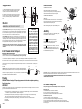
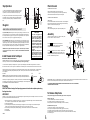
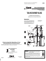
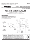
1
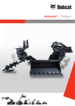
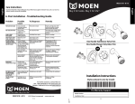
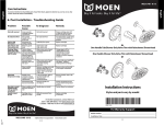
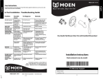
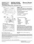
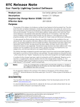
MODELS 2600, 2700, 5401, 62600, 62700, 72615, 72700 and MODEL SERIES T471,
T473, T555, T666, T777, T888, TL470, TL471, TL473, L2600, L2700
MT662C
®
INSTALLATION INSTRUCTIONS
THESE INSTRUCTIONS MUST BE
LEFT WITH HOMEOWNER
TUB AND SHOWER VALVES
Available with three or four port castings, with and without stops.
Connections are either 1/2 inch I.P.S. pipe or 1/2 inch copper sweat connections.
If the Moen Slip Fit spout is used, a 1/2 inch copper drop and lookout may be used.
Measurements
IMPORTANT: SEE FLUSHING
INSTRUCTIONS PAGE 2
These are shown in the drawings. The depth measurement is critical.
Use the front face of the plaster ground as a reference point for the finished wall position, including tile (2-1/16" [52mm]). The center line of
the supply and discharge piping should be a maximum of 2-3/16" (56mm)
and a minimum of 1-7/16" (37mm) behind the finished wall surface.
TUB/SHOWER
COMBINATION
FLANGE
FINISHED WALL
LINE
TUB FILLER
OR SHOWER
SHOWERHEAD
SHOWER
ARM
A
HANDLE
COVER
HANDLE
KNOB
WASHER
ESCUTCHEON
HANDLE
LEVER
HANDLE
SCREW
PLASTER
GROUND
2-1/16"
(52mm)
2-1/16"
(52mm)
6' 6"
1-1/4" (1981mm)
(32mm)
SUPPLY
SUPPLY
B
15/16"
(24mm)
STOP TUBE
HANDLE LEVER
To Eliminate Cross-Piping On Back-To-Back Installations or To Correct
Reversed Rough-In Where Hot and Cold Positions Are Reversed:
Remove handle knob or handle lever and handle parts (see "Disassembly"). Turn valve stem around so that the notched flat is turned one half turn or
180 degrees. Re-install handle parts and handle knob or lever. Tighten handle screw securely; replace handle parts.
HANDLE SCREW
C
32"
(813mm)
HEXAGONAL
WRENCH
WASHER
SET SCREW
STOP TUBE
HANDLE ADAPTER &
BRAKE ASSEMBLY
FLOOR
45"
(1143mm)
48"
(1219mm)
CAUTION
USE 1/2"
IRON PIPE
SIZE
MINIMUM
OR 1/2"
TUBING.
HELPLINE: Call our toll free Helpline number,
(800) BUY-MOEN
(289 - 6636)
for answers to any product, installation, replacement
parts, or warranty questions.
®
MT662C MAR01
25300 Al Moen Dr., North Olmsted, OH 44070-8022 U..S.A.
Always turn water off before installing or disassembling the valve. Open
valve handle to relieve water pressure and to insure that complete water
shut-off has been accomplished.
Before turning water on during either rough-in or trim-out, make sure that cartridge retainer clip is in place. The
cartridge and retainer clip were properly installed and tested before leaving the factory. Although it is unlikely, it
is nevertheless possible that through the handling of the valve by any number of persons the retainer clip may
not be properly installed. This should be carefully checked at time of rough-in and trim-out. If the retainer clip
is not properly installed, water pressure could force the cartridge out of the casting. Personal injury or water
damage to the premises could result.
CAUTION:
© Moen Incorporated 1996
Printed in U.S.A.
CLIP
CLIP
EAR
EAR
Stop Operation
WITHOUT STOPS
7" DIA
(178mm)
‰
CC - This type is integral with casting, actuated by screwdriver, and require a
90° turn to open or close. When the screwdriver slot is vertical, the rubber
stop is closed, and when the slot is horizontal, the rubber stop is open.
SHOWER
‰
SHOWER
‰
‰
SUPPLY
‰
‰
TUB
2" CC
(51mm)
‰
‰
2-3/16" IPS
(56mm)
Install Shower Arm & Tub Spout
STOP
TUBE
COVER
SNAP ON STYLE
Insert a flat bladed screwdriver into the screw hole access. Push the retaining arm
towards the outside of the plaster ground until it disengages from the valve body.
Repeat for other side and remove plaster ground.
SCREW STYLE
Remove screw holding plaster ground in place. Discard plaster ground.
‰
6" FOR I.P.S.
(152mm)
MAKE SURE ALL WATER SUPPLIES ARE OFF.
WARNING: Secure all pipes and the shower and tub drop ells. Use thread seal tape on all threads.
Use a plain ell on the tub drop. A twin ell is not needed. CHECK SYSTEM FOR LEAKS BEFORE
CLOSING WALL.
SCREW
HOLE
ACCESS
TO REMOVE THE PLASTER GROUND:
4-5/8" FOR C.C.
(117mm)
‰
3-port (2600 SERIES): These models may be used as either a shower or a tub filler. Since they are factory set in the shower position, with the outlet up, you must reverse the position of the cartridge retainer
clip when using the valve as a tub filler. Accomplish this change during the assembly process. Remove
the stop tube, pull the clip out from the bottom of the casting, rotate cartridge stem 180° and replace clip in
the top, then proceed with assembly, using 1/2" iron pipe size or 1/2" copper water tube.
4-1/2"
(114mm)
PLASTER GROUND
SIZE AND WALL
OPENING
2-1/8" CC
(54MM)
‰
‰
3-3/4" IPS
(95MM)
Place a flat bladed screwdriver into the slot at the base of the
stop tube cover near a support tab as you did when removing protective cap.
Twist the screwdriver until tab breaks. Repeat for remaining tabs.
‰
‰
RUBBER STOP VALVE
(WITH SCREW DRIVER SLOT)
4- port: (2700 SERIES): Install casting with "UP" at the top (arrow pointing up). If the valve is to be used
for both a shower and a tub, connect the top outlet to the shower (36" minimum riser) and the bottom outlet to the tub (6" minimum drop), using 1/2" iron pipe size or 1/2" copper water tube, 5/8" O.D. (If the valve
is to be used for a shower only or a tub only, plug the outlet not being used.)
SUPPLY
‰
TUB
SUPPLY
‰
‰
PROTECTIVE
CAP
TO REMOVE STOP TUBE COVER:
‰
SUPPLY
‰
Rough-In
7" DIA
(178mm)
‰
‰
IPS - This type has been added to the basic shower casting and is actuated
by screwdriver. The stop is opened by rotating in a counterclockwise direction until it stops and closed by rotating in a clockwise direction until it bottoms.
Plaster Ground
WITH STOPS
‰
CAUTION
These valves are equipped with
Moen's long-life 1225 cartridge,
designed for smooth, trouble free
operation. When soldering, do not
heat valve any higher than necessary to flow the solder. Overheating
may damage the cartridge or rubber
stop valves. Following this direction will allow you to solder without
removing the cartridge or rubber
stop valves.
WARNING: The cartridge and rubber stop valves MUST be removed
before either brazing or resistance
(electric) soldering. For stop valve
removal instructions, see last page.
Assembly
Use pliers to operate the cartridge. Turn on water and check system
for leaks. If there are no leaks, turn OFF water.
ALWAYS KEEP POINTER UP
WASHER
A
For style A & B : Install escutcheon plate and stop tube.
The notched flat on the cartridge stem must point UP. Install
handle parts as shown in the exploded parts view.
NOTCHED FLAT
ON STEM
RETAINER
CLIP
STOP
TUBE
HANDLE
KNOB
HANDLE
LEVER
EAR
CARTRIDGE
C
SHOWER: Install flange on long end of arm. Wrap threads on both ends of shower arm with thread seal tape.
Screw long end of shower arm into wall. Do not install showerhead prior to flushing (see Flushing).
STOP TUBE
C.C. SPOUT: The Moen Slip Fit spout is designed with an O-ring seal. It is specifically designed for installation with copper water tube. Lookout must
be free from burrs inside and out. The edge must not be rolled inward from a dull tubing cutter. The outside surface must be free from nicks and scratches.
HANDLE ADAPTER &
HANDLE
BRAKE ASSEMBLY
LEVER
SCREW
C
H
Press and twist the spout onto the lookout upside down. Tighten the clamp screw with a 5/32" hex wrench until it just starts to bind. Turn spout upright into
position against the wall and finish tightening the clamp screw by hand. The use of pliers or another wrench on the hex wrench is not necessary.
Do not overtighten.
C.C.
SET
SCREW
I.P.S.
CLAMP SCREW
Screw tub spout onto pipe and tighten by hand. If final turn by wrench is needed, use small wrench with smooth
jaws; otherwise, pad wrench teeth with rag. Pull outward on spout while tightening to avoid scratching the wall.
DO NOT INSERT TOOL INTO SPOUT END TO TURN SPOUT.
Flushing
IMPORTANT: Before closing all wall openings, pressure test valve and complete system using
flushing instructions
IMPORTANT:
Pipe chips, sand, stones, and other solids found in new or renovated plumbing can damage the sealing surface of the cartridge and cause a leak. To avoid damage, DO NOT TURN ON SUPPLY VALVES until instructed below:
1. Break off the protective cap on the plaster ground at the top end of the stop tube cover (see illustration page 3). Place a flat bladed screwdriver into
one of the slots near a support tab and twist to break. Repeat at remaining tabs.
2. Use pliers to operate cartridge.
3. Open the cartridge in the full cold position (notched flat pointing to the right) and turn on the cold supply for 15 seconds. Without closing the
cartridge, turn to the full hot position (notched flat pointing to the left) and turn on the hot supply for 15 seconds.
4. Turn the cartridge to the mixed position (notched flat pointing up), divert water to the shower and run for an additional 15 seconds.
5. Close cartridge.
6. Install showerhead.
MT662C
HANDLE
COVER
B
For style C : Attach stop tube to the valve body. Next, attach the
escutcheon using provided hardware. Place the washer on the
cartridge stem and attach the adapter and brake assembly using
the screw. Attach handle using set screw.
MAKE SURE ALL WATER SUPPLIES ARE OFF.
IPS SPOUT:
CAUTION: This spout is A.B.S. plastic and will crack when in contact with some pipe thread compounds.
Please read the pipe compound label to be certain. We recommend using thread seal tape thread sealant.
HANDLE
SCREW
IMPORTANT FINAL CHECK - ALL INSTALLATIONS: If above instructions have been followed correctly there will be clearance between the handle and the
escutcheon when the handle is pushed into the closed position, otherwise the valve will not shut off.
TO UTILIZE THE MAXIMUM TEMPERATURE LIMIT FEATURE AVAILABLE WITH THE STYLE C LEVER MODELS,
SEE INSTRUCTIONS ON BACK PAGE.
To Remove Stop Valve
Always turn water supply OFF before disassembly. Open faucet to relieve pressure.
Removal of stop valve:
1. Remove handle assembly as shown above and escutcheon.
2. Using snap ring pliers, remove retaining ring from valve body.
3. Grip stop valve stem with pliers and rotate slightly to remove from valve body.
Re-Installation of new stop valve:
1. Check to be sure that stop valve stem is fully seated in plug.
2. Insert stop valve until fully seated beyond retaining ring groove in valve body.
3. Using snap ring pliers, place retaining ring in valve body, making sure that ring is fully seated.
4. Check orientation of stop valve for water flow. (Stop is in the off position when screwdriver slot is vertical).
5. Turn water supply on.
MODELS 2600, 2700, 5401, 62600, 62700, 72615, 72700 and MODEL SERIES T471,
T473, T555, T666, T777, T888, TL470, TL471, TL473, L2600, L2700
MT662C
®
INSTALLATION INSTRUCTIONS
THESE INSTRUCTIONS MUST BE
LEFT WITH HOMEOWNER
TUB AND SHOWER VALVES
Available with three or four port castings, with and without stops.
Connections are either 1/2 inch I.P.S. pipe or 1/2 inch copper sweat connections.
If the Moen Slip Fit spout is used, a 1/2 inch copper drop and lookout may be used.
Measurements
IMPORTANT: SEE FLUSHING
INSTRUCTIONS PAGE 2
These are shown in the drawings. The depth measurement is critical.
Use the front face of the plaster ground as a reference point for the finished wall position, including tile (2-1/16" [52mm]). The center line of
the supply and discharge piping should be a maximum of 2-3/16" (56mm)
and a minimum of 1-7/16" (37mm) behind the finished wall surface.
TUB/SHOWER
COMBINATION
FLANGE
FINISHED WALL
LINE
TUB FILLER
OR SHOWER
SHOWERHEAD
SHOWER
ARM
A
HANDLE
COVER
HANDLE
KNOB
WASHER
ESCUTCHEON
HANDLE
LEVER
HANDLE
SCREW
PLASTER
GROUND
2-1/16"
(52mm)
2-1/16"
(52mm)
6' 6"
1-1/4" (1981mm)
(32mm)
SUPPLY
SUPPLY
B
15/16"
(24mm)
STOP TUBE
HANDLE LEVER
To Eliminate Cross-Piping On Back-To-Back Installations or To Correct
Reversed Rough-In Where Hot and Cold Positions Are Reversed:
Remove handle knob or handle lever and handle parts (see "Disassembly"). Turn valve stem around so that the notched flat is turned one half turn or
180 degrees. Re-install handle parts and handle knob or lever. Tighten handle screw securely; replace handle parts.
HANDLE SCREW
C
32"
(813mm)
HEXAGONAL
WRENCH
WASHER
SET SCREW
STOP TUBE
HANDLE ADAPTER &
BRAKE ASSEMBLY
FLOOR
45"
(1143mm)
48"
(1219mm)
CAUTION
USE 1/2"
IRON PIPE
SIZE
MINIMUM
OR 1/2"
TUBING.
HELPLINE: Call our toll free Helpline number,
(800) BUY-MOEN
(289 - 6636)
for answers to any product, installation, replacement
parts, or warranty questions.
®
MT662C MAR01
25300 Al Moen Dr., North Olmsted, OH 44070-8022 U..S.A.
Always turn water off before installing or disassembling the valve. Open
valve handle to relieve water pressure and to insure that complete water
shut-off has been accomplished.
Before turning water on during either rough-in or trim-out, make sure that cartridge retainer clip is in place. The
cartridge and retainer clip were properly installed and tested before leaving the factory. Although it is unlikely, it
is nevertheless possible that through the handling of the valve by any number of persons the retainer clip may
not be properly installed. This should be carefully checked at time of rough-in and trim-out. If the retainer clip
is not properly installed, water pressure could force the cartridge out of the casting. Personal injury or water
damage to the premises could result.
CAUTION:
© Moen Incorporated 1996
Printed in U.S.A.
CLIP
CLIP
EAR
EAR