1
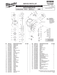
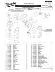
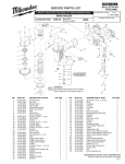
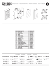
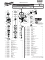
PAGE 1 OF 2 BULLETIN NO. SERVICE PARTS LIST 54-43-0020 REVISED BULLETIN SPECIFY CATALOG NO. AND SERIAL NO. WHEN ORDERING PARTS CLIPPED HEAD FRAMING NAILER WIRING INSTRUCTION STARTING SERIAL NUMBER CATALOG NO. 7110-20 A86A 57 1 54 30 20 2 21 99 50 86 6 59 31 41 32 22 8 58 60 53 4 5 55 56 52 51 3 47 36 33 43 35 42 34 37 38 46 23 45 7 44 39 40 9 31 32 33 34 35 36 102 37 38 39 40 41 50 00 0 48 24 25 13 64 FIG. 65 12 26 14 27 15 66 67 68 16 28 17 18 29 19 FIG. PART NO. 1 2 3 4 5 6 7 8 9 10 11 12 13 14 15 16 17 18 19 20 21 22 23 24 25 26 05-84-0945 45-88-1725 31-05-0410 45-88-1715 43-31-0350 05-84-0865 42-92-1430 05-84-0955 45-06-0900 40-50-3115 34-40-3255 34-40-3230 34-40-3260 44-62-0255 42-76-0805 31-94-0100 45-06-0930 05-83-0520 44-90-0745 44-90-0735 44-90-0810 34-40-3135 43-12-0275 42-98-0360 34-40-3140 44-90-0795 DESCRIPTION OF PART Deflector Bolt Deflector Screw Pad Deflector Deflector Pad Muffler Assembly Bolt Assembly w/Washer Top Cap Set Screw, M5 x 0.8-5 Top Cap Seal Upper Valve Spring O-Ring, 43.5 mm x 2.62 mm O-Ring, 60.2 mm x 3.1 mm O-Ring, 47.8 mm x 2.62 mm Head Valve Piston Valve Collar Valve Seal Hex Bolt, M6 x 1.0-12 Steel Ring Press Ring Piston Ring O-Ring Driver Assembly Cylinder O-Ring Cylinder Spacer EXAMPLE: Component Parts (Small #) Are Included When Ordering The Assembly (Large #). 49 63 10 11 DATE Feb. 2007 69 70 71 72 NO. REQ. 1 1 1 1 1 4 1 1 1 1 1 1 1 1 1 1 1 4 1 1 1 1 1 1 1 1 27 28 29 30 31 32 33 34 35 36 37 38 39 40 41 42 43 44 45 46 47 48 49 50 51 52 53 54 55 56 57 58 59 60 63 64 65 66 67 68 69 70 71 72 PART NO. 34-40-3150 44-90-0720 42-38-0310 42-38-0375 34-40-3295 34-40-3300 42-52-0410 34-40-3280 34-40-3285 44-70-0250 40-50-3195 34-40-3290 44-70-0255 43-64-0150 06-65-1465 06-65-1440 06-65-1435 43-56-0875 44-10-0655 40-50-3095 44-86-0710 40-50-3160 31-92-0200 44-90-0825 28-50-0810 44-90-0755 43-31-0375 42-92-1360 34-40-3225 05-84-0950 40-50-3180 45-08-0460 42-70-0405 05-83-0535 40-50-3070 44-90-0775 42-36-2020 44-94-0550 43-98-0750 40-50-3175 42-36-2000 44-90-0705 42-38-0330 44-90-0715 DESCRIPTION OF PART O-Ring Cylinder Ring Bumper Bumper Band O-Ring O-Ring Plunger Cap O-Ring O-Ring Valve Plunger Spring O-Ring Trigger Valve Plunger Trigger Valve Head Spring Pin Spring Pin Spring Pin Work Contact Element Guide Selector Selector Spring Retainer Trigger Spring Trigger Assembly Ring Tool Body Retaining Ring Inlet Filter End Cap O-Ring Socket Hex Head Screw Spring Positioning Shaft Spring Retainer (Rafter Hook) Round Head Philips Bolt Work Contact Spring E-Ring Work Contact Bracket B Adjust Rod Assembly Adjustment Knob Adjustment Spring Work Contact Bracket A Ring No-mar Pad Fixed Ring NO. REQ. 1 1 1 1 1 1 1 1 2 1 1 2 1 1 2 3 1 1 1 1 1 1 1 1 1 1 1 1 1 1 1 1 1 1 1 1 1 1 1 1 1 1 1 1 MILWAUKEE ELECTRIC TOOL CORPORATION 13135 W. Lisbon Road, Brookfield, WI 53005 Drwg.3 99 86 94 91 90 88 95 92 18 87 74 62 73 91 90 100 89 61 93 101 90 75 83 96 85 79 80 81 82 77 18 97 105 98 84 78 76 104 75 76 77 78 79 80 103 81 82 83 84 85 87 FIG. 61 62 73 74 75 76 77 78 79 80 81 82 83 84 85 86 87 88 89 PART NO. 34-40-3145 30-61-0210 05-84-0870 43-40-0480 43-72-0365 40-50-3135 42-28-0370 05-84-0885 40-50-3145 44-96-0200 06-65-1400 42-92-1525 44-86-0705 44-60-1920 44-86-0700 45-88-1765 05-84-0930 05-59-2030 05-83-0500 DESCRIPTION OF PART O-Ring Nose Piece Bolt Assembly Magazine A Pusher Pusher Button Spring Square Stop Bracket Socket Hex Head Screw Spring Spring Roller Pin Protecting Hood Cover Retainer Ring Trigger Pivot Pin Urethane Retainer Flat Washer Socket Hex Head Screw Lock Nut Half Round Hd. Hex. Bolt NO. REQ. 1 1 4 1 1 1 1 1 1 1 1 1 1 1 1 1 1 2 1 FIG. PART NO. 90 91 92 93 94 95 96 97 98 99 100 101 102 103 104 105 05-59-2020 05-83-0510 44-66-1320 42-92-1460 44-81-0065 42-36-2040 42-92-1530 45-88-1750 42-92-1505 05-84-0935 05-59-2035 45-88-1785 31-94-0110 45-24-0015 12-98-0300 10-20-3320 14-70-0135 14-70-0155 DESCRIPTION OF PART Lock Nut Half Round Hd. Hex. Bolt Nail Stop Plate Magazine End Cover Magazine Channel Magazine Bracket Lever Cover Flat Washer Work Contact Element Cover Socket Hex Head Screw Nut Flat Washer Trigger Valve Assembly Magazine Pusher Assembly Service Nameplate Warning Label Overhaul Kit (Not Shown) Driver Maintenance Kit (Not Shown) NO. REQ. 1 1 1 1 1 1 1 1 1 1 1 1 1 1 1 1 1 1 BULLETIN NO. 54-43-0020 Feb. 2007 PAGE 2 OF 2 Disassembly: 7, 10, 11, 12, 13, 14, 15, Remove valve assembly (10-17) from top cap (7) by removing hex bolt (18) in a counter clockwise direction. 16, 17, 18 Note: Assembly is spring loaded. Hold assembly in place while removing hex bolt (18). 23, 24, 51, 19, 20 Remove driver assembly (23) and cylinder assembly (24) from tool body (51) by turning the tool body (51) upside down and tapping the outside rim of the tool casting against a piece of wood. Note: Remove press ring(s) (19 and 20) prior to removing cylinder assembly. 51, 74, 86, 87, 99, 100, Remove magazine (74) from tool body (51) by removing bolts, washers (87 101, 99, 86), and nut (100) using a 5 mm hex 101 key and 10 mm wrench. 103, 74, 79, 89, 90 Remove magazine pusher assembly (103) and spring ( 79) from magazine (74) by pushing assembly back far enough to clear lock nut (90); secure nut using a 7 mm socket, and remove hex bolt (89) from pusher spring (79) using a 2.5 mm hex key. 42 43 45, 46, 47, 48, 49 Remove trigger valve assembly (102) from tool body (51) by placing a 3/32 in. (2.5mm) punch inside half-moon slot of 50 51,102, retainer (47) and gently tapping shaft of selector (45). Remove spring (46), retainer (47) and ring (50). Remove trigger (49) and spring (48) from tool body. Push pins (42, 43) out of tool body (51) just far enough to remove valve assembly. Note: Use service fixture #61-60-0005 to move spring pins (42, 43) or a 1/8” punch. 51-54 Remove end cap (54) from tool body (51) counterclockwise. Reassembly: Note: Apply a thin coat of grease to all o-rings, exterior of cylinder seals, and trigger valve assembly before replacement or reinstallation. 24, 25 26, 27, 28, 29 Install o-ring (25) onto cylinder (24) and place remaining parts (26, 27, 28, and 29) onto cylinder (24). Note: Install cylinder ring (28) onto cylinder (24) with the ribbed edge up. Set aside 21, 22, 23, 51 Install o-ring (22) and piston ring (21) onto driver assembly (23) and place assembly inside cylinder (24). Install assembly into tool body (51) Note: Be sure driver shaft is inserted in the proper orientation. 19, 20, 24 Cupped side of steel press ring (19) to face cupped side of nylon press ring (20) in assembly. 7, 10, 11, 12, 13, 14, 15, Reinstall valve assembly components (10-17) into internal bore of top cap (7) and secure assembly with hex bolt (18). 16, 17, 18, Tighten screw clockwise. Note: Valve assembly is spring-loaded and must be held in place when reinstalling screw (18). 7, 30, 51 Align four raised bosses on bumper band (30) with slots on top cap (7) prior to assembling cap onto tool body (51). 42 43 51,102 Reinstall trigger valve assembly (102) into tool body (51) by making sure the grooves in the valve assembly match up with the two holes for spring pins (42,and 43). Tap pins into tool body until they are flush with casting. 45, 47, 50 Reinstall retainer assembly (47and 50) onto shaft of selector (45) by aligning half-moon cut-out on retainer with half-moon of selector shaft and snap it onto end of selector shaft (45). 1 When reinstall deflector-retaining screw (1), apply Blue Loctite® 242 to threads of screw. 103, 74, 79, 89, 90 Reinstall pusher assembly (103) into track of magazine (74). Make sure bend of spring (79) slides over top magazine connection point, and push assembly back just far enough to install bolt (89) through top of magazine track and hole in spring (79). Install nut (90) onto threads of bolt (89) and secure using a 2.5 mm hex key and 7 mm socket. 62, 74, 87, 101 Reinstall front of magazine assembly (74) to nosepiece (62) and install screw and washer (87,101) using a 5 mm hex key. 51, 74, 86, 99, 100 Reinstall back of magazine (74) to tool body (51), and install screw (99), washer ( 86) and nut (100) using a 5 mm hex key and 10 mm wrench. Lubrication: Type I Grease 49-08-7100 Clean all parts with a dry clean cloth. 7, 10, 11, 12, 13, 14, 15, Place a thin coating of grease into internal bore of top cap (7), coat parts (10-17) and reassemble in order shown. 16, 17 21, 22, 23 Coat o-ring (22) and piston ring (21) prior to installing into groove of driver assembly (23). 24, 25, 27, 28 Coat cylinder o-rings (25, 27) and cylinder ring (28) prior to installing onto cylinder (24). 31, 32 33, 34, 35, 36, 37, Coat all parts of the trigger valve assembly if being replaced individually. Components cleaned in any type of solvent or 38, 39, 40, 41 water solution will require new lubrication. Note: A new trigger valve assembly will be pre-lubricated and will not require any additional lubrication.