1
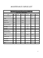
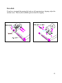
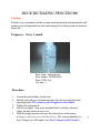
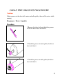
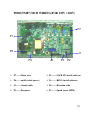
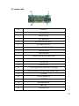
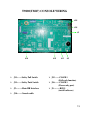
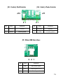
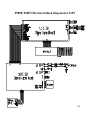
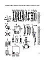
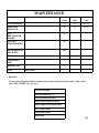
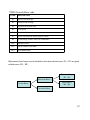
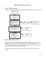
Vision T9800HRT
Service Manual
1
TABLE OF CONTENTS
SECTION 1: MAINTENANCE PROCEDURE …………………3
1.
2.
3.
4.
MAINTENANCE CHECK LIST………………………..............................4
TENSIONING THE BELT PROCEDURE………………………….……..5-6
DECK RE-WAXING PROCEDURE………………………………….……7
CLEAN THE GROOVES PROCEDURE…………….................................8
SECTION 2: WIRING DIAGRAM INSTRUCTION……………….9
1.
2.
3.
4.
5.
6.
7.
8.
T9800(TM87) MCB WIRING(FOR 110V / 220V)………………………..10
T9800(TM87) MCB WIRING DEFINITION OF PIN…………...………..11-12
T9800(TM87) CONSOLE WIRING………………………………………..13
T9800(TM87) CONSOLE WIRING DEFINITION OF PIN……………....14-15
T9800(TM87) ELECTRICAL BLOCK DIAGRAM FOR 110V……….….16
T9800(TM87) WIRING DIAGRAM INSTRUCTION for 110V………..…17
T9800(TM87) ELECTRICAL BLOCK DIAGRAM FOR 220V..………….18
T9800(TM87) WIRING DIAGRAM INSTRUCTION for 220V…………..19
SECTION 3: CONSOLE FUNCTIONAL FLOW DIAGRAM……20
1.
2.
OPERATION T9800 MANUAL…………………………………………….21
OPERATION T9800 MANUAL- Engineer mode……………………..…...22-26
SECTION 4: MCB LED INSTRUCTIONS……….……… …….….27
1.
T9800 MCB LED PLACE AND DEFINITION…………………………….28-29
SECTION 5: TROUBLESHOOTINGS………………………………………30
1.
2.
3.
4.
5.
6.
7.
8.
9.
10.
11.
12.
13.
T9800 Console Error code …………………………………………..……...31
E1 - Reverse Elevation Pot ………………………………………………….32
E2 – Elevation Out Of Range …………………………………………….….33
E3 – Elevation Stall ……………………………………….............…………34
E5 – Over-speed Error ………………………………...………………….….35
E6 – Runaway Belt Error …………………………………………..………..36
E7 – Speed Stall Error…...…………………………………………………...37
E9 – Speed Range Error …...…………………..…………………….……...38-39
Speed Issues .……………………………………………………..…………40
Belt Drive Issues………………………………………………………….…41
Speed Control Issues……………………………………………….……….42
Speed Calibration Issue……………………………………………..………43 2
OPERATION ERRORS…………………………...………………………...44
SECTION 1
MAINTENANCE PROCEDURE
3
MAINTENANCE CHECK LIST
PREVENTIVE MAINTENANCE SCHEDULE
Vision T9800 TREADMILL
Item
Daily
Weekly
Monthly
Quarterly
Console Mounting Bolts
Frame
Biannual
Inspect
Clean
Power Cord
Inspect
Inspect
Display Console
Clean
Handrail & Handlebar
Clean
Inspect
Inspect
Front Roller
Clean
Inspect
Rear Roller
Clean
Inspect
Clean
Inspect
Emergency Button
Running belt Tension
Test
Inspect
V Belt
Deck Re-waxing
Inspect &
Re-waxing
Running Belt
Inspect
Control Board
Clean
(Vacuum)
Motor
Annual
Clean
4
TENSIONING THE BELT PROCEDURE
Caution:
Over-tightening of the roller will severely shorten the life of the belt and may cause
further damage to other components.
Frequency: Every 1 months
Running Belt:
If when you plant your foot on the belt, you can feel a slipping sensation then the belt
has stretched and is slipping across the rollers. This is a normal and common
adjustment on a new treadmill. To eliminate this slipping, tension both the rear
rollers Allen bolts 1/4 TURN as shown above. Try the treadmill again to check for
slipping. Repeat if necessary, but NEVER TURN the roller bolts more than 1/4
turn at a time.
Perfect Tension of Running Belt: 0.9~1.1 lbs
5
Drive Belt:
If you have tensioned the running belt and are still experiencing a slipping, adjust the
tension screw. Then try the treadmill again to check for slipping.
6
DECK RE-WAXING PROCEDURE
Caution:
If deck is not to periodical add the waxing, between the deck and running belt will
produce great friction make the deck and running belt to burn up and cut down the
motor life .
Frequency: Every 1 month
Parts name: Silicon oil set
Parts number: SZTM74SOS
Price (USD): 0.6
Use time : 1
Procedure:
1.
2.
3.
4.
5.
Loosen the tension bolts at both ends.
Pull the belt with your left hand and apply the silicon in the deck with
your right hand. (The volume of silicon applied is about 40ml)
Tighten the tension bolts.
Start the treadmill. Step on the treadmill belt to walk the silicon in.
Adjust the belt tension if necessary.
With the clamp-on meter, measure the current draw of the motor.
(Clamp on either the red or the black wire.) The current should be less
than 15Amps for 110V model. (less than 7.5Amps for 220V model.)
7
CLEAN THE GROOVES PROCEDURE
Caution:
If dirty grooves in the drive belt, motor and roller pulley, there will be noises while
running.
Frequency: Every 3 months
Procedure:
1.Remove the drive belt and check the grooves
in belt for dirt or dust and clean it.
2.Check the grooves in motor pulley for dirt or
dust and clean it
3.Check the grooves in roller pulley for dirt or
dust and clean it.
8
SECTION 2
WIRING DIAGRAM INSTRUCTION
9
T9800(TM87) MCB WIRING(FOR 110V / 220V)
P7
P1
P6
J1
P4
J2
P3
P2
P7-------Motor wire
P2--------SAFE SW (install software)
P6------ on/off switch (power)
J1--------RS232 (install software)
J2-------Console cable
P4--------Elevation cable
P1-------Fan power
P3--------Speed sensor (RPM)
10
T9800(TM87) MCB WIRING DEFINITION OF PIN
JP1:Elevation cable(6pin/AMP-350762-4)
1
4
2
5
3
6
P4
Pin
Name
Definition
1
ELVR_+5V
Incline place signal test power
2
ELVR_POT
Incline place signal
3
ELVR_GND
Incline place signal test ground
4
UP
Incline motor does move to up
5
DOWN
Incline motor does move to down
6
COM
Incline motor does turn on power
11
J2: console cable
20
2
19
1
Pin
Definition
1
Console ground
2
Motor Current
3
ELV REF GND
4
POT Wiper of ELV(0-5V)
5
ELV REF VOL.+5V
6
Speed. signal. (0-5V PULSE)
7
Console ground
8
Console ground
9
Console for MCB of the PWM signal
10
Console power
11
Console power
12
Console power
13
Console provide for incline motor UP signal
14
Console provide for incline motor DOWN signal
15
E_STOP
16
TX OUT(RESERVE)
17
RESERVE
18
RX IN(RESERVE)
19
ERR. SIG.
20
Console ground
12
T9800(TM87) CONSOLE WIRING
J15
J16
J1
J14
J13-------Safety Pull Switch
J11-------Safety Push Switch
J5---------Main HR Interface
J14-------Console cable
J13
J11
J5
J15-------CSAFE 1
(Full csafe function)
J16-------CSAFE 2
(Power only port)
J1---------RS232
(install software)
13
T8900(TM87) CONSOLE WIRING DEFINITION OF PIN
J14:20-pin console cable
19
20
1
2
J14
Pin
Definition
1
Console ground
2
Motor Current
3
ELV REF GND
4
POT Wiper of ELV(0-5V)
5
ELV REF VOL.+5V
6
Speed. signal. (0-5V PULSE)
7
Console ground
8
Console ground
9
Console for MCB of the PWM signal
10
Console power
11
Console power
12
Console power
13
Console provide for incline motor UP signal
14
Console provide for incline motor DOWN signal
15
E_STOP
16
TX OUT(RESERVE)
17
RESERVE
18
RX IN(RESERVE)
19
ERR. SIG.
20
Console ground
14
J13: Safety Pull Switch
J11: Safety Push Switch
J13
J11
21
21
Pin
Name
Definition
Pin
Name
Definition
1
SS OUT
Safe key
1
SS OUT
Safe key
2
SS IN
Console ground
2
SS IN
Console ground
J5: Main HR Interface
3 2 1
Pin
Name
Definition
1
HR2
Pulse Board signal
2
VCC
Console power (+5V)
3
GND
Console ground
15
T9800(TM87) Electrical block diagram for 110V
16
T9800(TM87) WIRING DIAGRAM INSTRUCTION for 110V
17
T9800(TM87) Electrical block diagram for 220V
18
T9800(TM87) WIRING DIAGRAM INSTRUCTION for 220V
19
SECTION 3
CONSOLE FUNCTIONAL FLOW DIAGRAM
20
OPERATING T9800
21
T9800 OPERATION MANUAL- Engineer mode
1. Press & Hold both “ELEVATION
” and “SPEED ” at the same time
for 5 sec. Then, the display will show
“Engineering Mode ”.
2. Press the "ELEVATION UP or
DOWN" to select you want and press the
“SELECT" key enter.
KEY BEHALE FUNCTION
UP
To scroll through the list of setting
DOWN
To scroll through the list of setting
FAST
Add this show parameter of speed
SLOW
Decrease this show parameter of speed
SELECT
To Store up the parameter
Set the data/function Step.
Use the elevation arrow keys to scroll through the available functions press
“SELECT” key enter, press the “SPEED” key to choose the data press
“SELECT” key to save the data/function.
To exit, press “STOP” key
22
Engineering Mode Menu
CONFIGURATION
SYSTEM TESTS
AUTO-CALIBRATION
MANUAL CALIBRATION
MAINTENANCE
SOFTWARE VERSION
EXIT
CONFIGURATION
Address
Description
Default
Value
Minimum
Value
Maximum
Value
P7 MAXIMUM
TIME
99
5
99
P22 DEFAULT
TIME
30
5
99
0:20
0:05
10:00
40
15
99
150
68
80
36
400
181
3
1
5
P6 T9800HRT
English,0.5-12 Mph,15% Incline for USA
P6 T9800HRT INT
Metric,0.8-20 Kph,15%Incline for ID
English,0.5-12 Mph,15% Incline for ID
P6 T9800S
English,0.5-12mph,15% Incline for USA
P24 UNITS
English/Metric
P23 PAUSE TIME
P27 DEFAULT AGE
P8 DEFAULT
WEIGHT
English
Metric
P15 SCROLL
SPEED
P30 Maximum Speed
English
Metric
P14 ELEVATION
ERRS—OFF
12.0 20.0
ON
Reset Novram
EXIT
Exits mode
23
MANUAL CALIBRATION
Address
Description
Default
Value
Minimum
Value
Maximum
Value
P0 PWM MIN
SPD
PWM value at min speed (0.5
mph/0.8kph)
34
1
111
P1 PWM 1/2
MAX
PWM value at 1/2 max speed (6.0
mph/10.0kph)
176
110
251
P2 PWM MAX
SPD
PWM value at max speed (12.0
mph/20.0kph)
341
249
486
P4 ELEVATION
MIN
Value at zero or minimum elevation
40
27
71
P5 ELEVATION
MAX
Value at maximum elevation
218
71
228
1
48
P13 ELV
DIRECTION
YES
P19 MAGNET
COUNT
26
P20 EFF
DIAMETER
67.8
P21 PWM
START SPD
30
1
~
P29 RAMP TIME
30
12
40
EXIT
Exits mode
Remarks:
Do not change the product below parameter , or it may cause malfunction.
Address
Default Value
P13 ELV DIRECTION
YES
P19 MAGNET COUNT
26
P20 EFF DIAMETER
P29 RAMP TIME
67.8
30
24
SYSTEM TESTS
HARDWARE TEST
DISPLAY TEST
KEYBOARD TEST
SAFETY SWITCH TEST
IO TEST
BURN-IN TEST
ELEVATION BURN-IN TEST
EXIT
MANUAL CALIBRATION
Address
Description
Default
Value
Minimum
Value
Maximum
Value
P0 PWM MIN SPD
PWM value at min speed (0.5 mph/0.8kph)
34
1
111
P1 PWM 1/2 MAX
PWM value at 1/2 max speed (6.0 mph/10.0kph)
176
110
251
P2 PWM MAX SPD
PWM value at max speed (12.0 mph/20.0kph)
341
249
486
P4 ELEVATION
MIN
Value at zero or minimum elevation
40
27
71
P5 ELEVATION
MAX
Value at maximum elevation
218
71
228
1
48
P13 ELV
DIRECTION
YES
P19 MAGNET
COUNT
26
P20 EFF
DIAMETER
67.8 341
P21 PWM START
SPD
30
1
~
P29 RAMP TIME
30
12
40
EXIT
Exits mode
25
MAINTENANCE
Address
Description
Default
Value
Minimum
Value
Maximum
Value
P9 Total HOURS
0
0
6533.5
P10 TOTAL
DISTANCE
0
0
65335
P25
BELT/MOTOR
HOURS
0
P26 LIFT
MOTOR HOURS
0
P16 LUBRICATE
DECK MSG
OFF
P17 CLEAN
0
TREADMILL
MSG
0
ERROR LOG
0
EXIT
Exits mode
Remarks:
If you want to the clean below parameter, please enter engineering mode select “below place”
enter, hold “START” key for 3 sec.
P9 Total HOURS
P10 Total DISTANCE
P25 Belt/Motor HOURS
P26 Lift (Elevation) HOURS
P16 LUBRICATE DECK MSG
P17 CLEAN MSG
TREAMILL MSG
Error Log
26
SECTION 4
MCB LED INSTRUCTIONS
27
AC FAN
28
LED
STATUS
Reference
Designator
Description
LED 1
Auxiliary Status LED
LED 2
Auxiliary Status LED
LED 3
Auxiliary Status LED
LED 4
Auxiliary Status LED/Digital to Analog Output.
LED 5
Main Status/Error LED.
AC
LED 6
Indicates if the DC Buss is Energized (Voltage Present).
+VCON
LED 7
Indicates if Console Voltage Supply is present.
VDSP
LED 8
Indicates if the DSP Power Supply is present.
DOWN
LED 9
Indicates if the upper console is commanding Elevation
DOWN.
UP
LED 10
Indicates if the upper console is commanding Elevation UP.
PWM
LED 11
Indicates if Console is commanding speed.
SPEED
LED 12
Indicates the motor is moving via the encoder's feedback by
blinking.
NORMAL OPERATION
1.
LEDs 1, 2 and 3 Sequence back and forth to indicate the processor is on-line and
operational.
2. LED 4 is used as a discrete/analog signal to the upper console.
3.
LED 5 indicates system status/mode. Currently 3 modes are defined safe mode,
stand-by mode and run mode. They are defined as follows:
a) Safe Mode - When the controllers safety relay is not energized and no error
exists, LED 5 remains off.
b) Stand-by Mode - When the safety relay is engaged but the system is not
outputting an active PWM to the motor and no error exists, LED 5 blinks off and
on at a fast rate.
c) Run Mode - When the system outputs an active PWM Control signal to the
29
motor and no error exists, LED 5 remains ON.
SECTION 5
TROUBLESHOOTINGS
30
T9800 Console Error code
CODE
DESCRIPTION
E1
Reverse elevation pot
E2
Elevation out of range
E3
Elevation movement stall
E5
Over-speed
E6
Runaway belt
E7
Speed stall (could be missing speed sensor)
E9
Speed Range (usually caused by calibration)
E16
Stuck key error
E18
Safety Switch Test Failure
E19
NOVRAM failure
Movement related errors can be divided in elevation related errors (E1 – E3) or speed
related errors (E5 – E9).
Elevation Errors
(E1 – E3)
Movement Errors
Speed Errors
(E5 – E9)
System Errors
Operation Errors
31
E1 - Reverse Elevation Pot
Step 1. Calibrate Elevation
Calibrate the elevation as outlined in the System Calibration Procedure in below step.
Error 1
Enter engineer mode of
“MANUAL
CALIBRATION”
screen
Check the “P13 ELV
DIRECTION” screen
whether set to “Yes”
Set to “Yes”
Enter the “P4 ELEVATION
MINIMUM” screen
whether parameter set is
30 2
AUTOCalibration
Enter the “P5
ELEVATION
MAXIMUM ” screen
whether parameter set is
240 5
AUTOCalibration
AUTOCalibration
Step 2. CORRECTIVE ACTION
1.Ensure correct signal is being sent to interface board (MCB) by pressing elevation
up/down keys by observing elevation LED’s correctly corresponding to correct
elevation keys pressed (please refer the 29 page) . If failure occurs for this step check
console cable and then the interface board (MCB).
2.Check failed elevation motor, interface board, console cable with a known good
console.
32
E2 – Elevation Out Of Range
Step 1. Calibrate Elevation
Calibrate the elevation as outlined in the System Calibration Procedure in below step.
Error 2
Enter engineer mode of
“MANUAL
CALIBRATION”
screen
Check the “P13 ELV
DIRECTION” screen
whether set to “Yes”
Set to “Yes”
Enter the “P4 ELEVATION
MINIMUM” screen
whether parameter set is
30 2
AUTOCalibration
Enter the “P5
ELEVATION
MAXIMUM ” screen
whether parameter set is
240 5
AUTOCalibration
AUTOCalibration
Step 2. CORRECTIVE ACTION
1.Check the failed system with a known good console cable. If fixed then
repair/replace the console cable.
2.Check the failed system with a known good elevation motor. If problem fixed then
repair/replace the elevation motor.
3.Check the failed system with a known good interface board. If problem fixed then
repair/replace the interface board (MCB).
4.Check the failed system with a known good console board with current software. If
the problem is fixed then repair/replace the console.
33
E3 – Elevation Stall
Step 1. Please refer the below PROBLEM IDENTIFICATION Step.
E3 Error
Check the “P13 ELV
DIRECTION” screen
whether set to “Yes”
AUTOCalibration
Set to “Yes”
Enter Hardware Test Screen
Run Elevation Up And Down
Treadmill
moves up or
down?
N
Motor
Overheated?
Waiting the Elevation
Motor to cool
N
Y
Feedback
Changes
Elevation
Y
Motor Movement Issue
Y
AUTO-Calibration
N
Position Feedback Problem
Step 2. CORRECTIVE ACTION
1.Allow elevation motor to cool.
2.Check the failed system with a known good console cable. If fixed then
repair/replace the console cables.
3.Check the failed system with a known good elevation motor. If problem fixed then
repair/replace the elevation motor.
4.Check the failed system with a known good interface board (MCB). If problem
fixed then repair/replace the interface board (MCB).
5.Check the failed system with a known good console board with current software. If
34
the problem is fixed then repair/replace the console.
E5 – Over-speed Error
OVERVIEW
If the actual speed from the speed sensor exceeds the system maximum speed by a limit
(currently 2 MPH) an over-speed error occurs (E5).
Step 1. AUTO CALIBRATION
AUTO-Calibration the as outlined in the System Calibration Procedure in below step.
Error 5
Enter engineer mode of
“AUTO
CALIBRATION”
Please will start Key
held for 3 seconds to
auto calibration
Measured speed <
14 MPH &
displayed speed >
14 MPH
Speed feedback
issue
Speed control issue
Speed Feedback Issues – See speed feedback issue trouble shooting guide in the
CORRECTIVE ACTION PROCEDURES – Speed Issues section of this document.
Speed Control Issues – See speed control issue trouble shooting guide in the
CORRECTIVE ACTION PROCEDURES – Speed Issues section of this document.
Step 2 :
1.Record when parameter information with error (please refer the 25 page of P1 / P2 /
P3 place) .
2.Remove Power!!! Carefully check all connections.
3.Check interface board (MCB) with the speed sensor ensure contact are correct and fix.
4. If AUTO CALIBRATION can't finish, please take speed sensor to be close to
magnet and AUTO CALIBRATION again.
5.If repeat over speed errors occur remove the treadmill from service.
35
E6 – Runaway Belt Error
OVERVIEW
If the actual belt speed is greater than the target speed by a limit and increasing then an
E6 error is called. E6 errors flag errors that will result in the belt “running away” or not
responding to input.
Step 1 :
Error 6
Before cycling power inspect the
motor controller for error
conditions
Motor Controller Error
Record error code information
from motor controller
Record console error code
parameters recorded with current
error code
Inspect all electrical connections,
ensure that all connections are properly
made and there are no shorts to
adjacent conductors
Speed feedback
issue
Speed control issue
Speed Feedback Issues – See speed feedback issue trouble shooting guide in the CORRECTIVE
ACTION PROCEDURES – Speed Issues section of this document.
Speed Control Issues – See speed control issue trouble shooting guide in the CORRECTIVE ACTION
PROCEDURES – Speed Issues section of this document.
Step 2 :
1.Remove Power!!! Carefully check all connections, interface board and the Reliance Motor
controller setting to ensure all settings are correct.
2. Enter the engineer mode to SERVICE 5, press "START" key to clean "ERROR LOG" and
refer the T5x Engineer mod parameter set SOP to confirm the machine parameter whether is
correct.
3. AUTO CALIBRATION again.
4. If AUTO CALIBRATION can't finish, please take the speed sensor to be close to magnet and
AUTO CALIBRATION again.
36
E7 – Speed Stall Error
OVERVIEW
If no belt movement is detected several seconds after commanding belt movement a speed
stall error (E7) is called.
Step 1 :
E7 Error
Enter firmware setup screen
Start PWM 1/2MAX test
N
Belt Moving
Belt drive issue
Y
Allow belt speed to stabilize and measure belt speed
Y
Measured speed different than
displayed speed
Speed Feedback Issue
N
Measured speed = 6.4
MPH
N
AUTO CALIBRATION
Y
Displayed speed = 0
N
AUTO CALIBRATION
Y
Speed feedback missing
Step 2 :
Belt Drive Issues – See belt drive issue trouble shooting section in the CORRECTIVE
ACTION PROCEDURES – Speed Issues section of this document.
Speed Feedback Issues – See speed feedback issue trouble shooting section in the
CORRECTIVE ACTION PROCEDURES – Speed issues section of this document.
Speed Feedback Missing Issues – See speed feedback issue trouble shooting section in the
CORRECTIVE ACTION PROCEDURES – Speed Issues section of this document.
37
Calibration Issues – See speed calibration issue trouble shooting section in the
CORRECTIVE ACTION PROCEDURES – Speed Issues section of this document
E9 – Speed Range Error
OVERVIEW
During normal run time operation the value stored during auto calibration is used to initially
set the speed (e.g. target speed = 12 MPH, PWM ticks = Maximum PWM = 363). Once the
speed stabilized the actual speed is monitored and if different than the target speed the PWM
value is adjusted until the actual speed matches the target speed. If the PWM value is
changed by more than the amount of ticks required to change 0.8 MPH and the actual speed
does not match the target speed then an E9 error is flagged. This error indicates the motor
controller system is unable to maintain the target speed.
E9 Error
Before cycling power inspect the
motor controller for error
Y
Motor
controller error
Record the error
code from the
motor controller
Check for free
movement of
belt roller
movement
Cycle
Power
Run auto
calibration
Done
N
Start PWM ½ MAX test
Measure speed and compare
to value displayed in time
window
N
OK
Perform steps outlined in speed
feedback issue
Y
Run Auto Calibration
N
Error
Gone
Perform steps outlined in
speed control issue
Y
Done
38
Speed Feedback Issues – See speed feedback issue trouble shooting section in the
CORRECTIVE ACTION PROCEDURES – Speed Issues section of this document.
Speed Control Issues – See speed control issue trouble shooting guide in the CORRECTIVE
ACTION PROCEDURES – Speed Issues section of this document.
Calibration Issues – See speed calibration issue trouble shooting section in the CORRECTIVE
ACTION PROCEDURES – Speed Issues section of this document.
39
CORRECTIVE ACTION PROCEDURES – Speed Issues
Speed Feedback Issue
Perform steps in order listed until
problem resolved.
1.
.Check connections
2.
.Check magnet
orientation (correct
poles)
3.
.Check sensor
mounting
4.
.Replace sensor w/
known good sensor
5.
.Replace interface PCB
with known good PCB
Enter Magnet Count
screen
N
Magnet count
= treadmill #
of magnets
Adjust magnet count
to match number of
magnets
Re-run test
Y
Manually rotate belt and check
for only 1 speed pulse on
interface board per magnet
(check all magnets)
N
N
OK?
Enter effective
diameter screen
of firmware
setup
Pulse
only one
magnet
Y
Y
Perform steps in order listed
until problem
resolved.
1.
Check connections
2.
Check magnet
orientation (correct
poles)
3.
Check sensor
mounting
4.
Replace sensor w/
known good sensor
5.
Replace interface
PCB with known
good PCB
Setup effective
diameter as
described in
system
calibration
section of this
document
N
N
No pules
for either
magnet
Perform steps in
order listed
until problem
resolved.
1.
Check magnet
orientation
(correct poles)
2.
Check sensor
mounting
3.
Replace sensor
w/ known
good sensor
Multiple
pulse per
magnet
Y
Perform steps in order listed until
problem resolved.
1.
If reed type sensor replace
with Hall type sensor or
correctly orient sensor.
2.
Check connections
3.
Check sensor mounting
4.
Replace sensor w/ known
good sensor
Y
Problem
Fixed
N
Perform steps in order listed until
problem resolved.
1.
Check connections
2.
Check magnet orientation
(correct poles)
3.
Check sensor mounting
4.
Replace sensor w/ known good
sensor
5.
Replace interface PCB with
known good PCB
6.
Replace console PCB with
know good PCB
Re-calibrate
system
Done
40
CORRECTIVE ACTION PROCEDURES – Belt Drive Issues
Belt Drive Issue
Start PWM max test (firmware setup
screens), wait 20 seconds
Check PWM LED on interface PCB
N
PWM LED
illuminated
Perform steps in order listed until problem
resolved.
1.
.Replace ribbon cable with
known good ribbon cable.
2.
.Replace interface PCB with
known good interface PCB.
3.
.Replace console PCB with a
known good console PCB.
Y
Perform steps in order listed until problem resolved.
1.
.Ensure belt and drive is able to turn
freely and are properly mechanically
connected.
2.
.Check all electrical connections
3.
.Verify reliance drive settings
4.
.Replace ribbon cable with a known
good cable
5.
.Replace interface PCB with a known
good PCB
6.
.Replace console PCB with a known
good PCB
41
CORRECTIVE ACTION PROCEDURES – Speed Control Issues
Speed Control Issue
Start PWM max test (firmware setup screens), wait
20 seconds or until speed stabilizes
N
See belt drive issue
Belt moving
Y
Measure speed and compare to value displayed in
time window
N
OK
Speed feedback issue
Y
Run Auto Calibration (firmware setup)
Problem Fixed
Y
Done
N
Perform steps in order listed until problem resolved.
1.
.Ensure belt and drive is able to turn freely and are
properly mechanically connected.
2.
.Check all electrical connections
3.
.Verify reliance drive settings
4.
.Replace ribbon cable with a known good cable
5.
.Replace interface PCB with a known good PCB
6.
.Replace console PCB with a known good PCB
42
CORRECTIVE ACTION PROCEDURES – Speed Calibration Issue
Speed Calibration Issue
Run auto calibration (firmware setup screen)
Y
Auto calibration
passed
Done
N
Start PWM max test (firmware setup screen),
wait minimum 20 seconds or until sped
stabilizes
Measure speed and compare to value
displayed in time window
N
OK
Check speed feedback
issue
Y
Check speed control issue
43
OPERATION ERRORS
E16 – Stuck key error
OVERVIEW
If a key press is detected for more than 45 seconds a stuck key error is flagged. This error is
primarily caused by a faulty keypad but could be caused by other issues (object on the
keypad).
CORRECTIVE ACTION
Reset system power. If error re-occurs replace the keypad with a known good keypad. If
error still occurs replace console PCB with known good console PCB.
E18 – Safety switch test failure
OVERVIEW
If the actual speed exceeds limit set for safety switch test a safety switch test failure error
occurs..
CORRECTIVE ACTION
Re-calibrate system as listed in system calibration section of this document and re-run safety
switch test. If system still fails safety switch test run speed feedback issue and speed control
issue tests in the corrective action procedures section of this document.
E19 – NOVRAM Failure
OVERVIEW
If the values stored in non-volatile memory are out of limits or do not match the safety check
value stored in non-volatile memory a NOVRAM failure occurs. The system attempts to reinitialize the non-volatile memory three times and if the NOVRAM check fails all three
attempts a NOVRAM failure error (E19) is called.
CORRECTIVE ACTION
An E-19 error indicates the NOVRAM has critically failed and needs to be replaced. If an E19
error occurs the console should be reprogrammed with the current software version and the
power should be toggled. If this does not clear the E-19 error the console PCB will need to be
returned to DCI for repair.
44