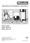
1
Operating and Installation
Instructions
Wine Storage Unit
KWT 1601 Vi
KWT 1611 Vi
To prevent accidents
and appliance damage
read these instructions
before
installation or use.
en - US, CA
M.-Nr. 07 682 490
Contents
IMPORTANT SAFETY INSTRUCTIONS. . . . . . . . . . . . . . . . . . . . . . . . . . . . . . . . . 4
Guide to the wine storage unit . . . . . . . . . . . . . . . . . . . . . . . . . . . . . . . . . . . . . . . 7
Before use . . . . . . . . . . . . . . . . . . . . . . . . . . . . . . . . . . . . . . . . . . . . . . . . . . . . . . . 9
Before using for the first time . . . . . . . . . . . . . . . . . . . . . . . . . . . . . . . . . . . . . . . . . . 9
Turning the appliance On/Off . . . . . . . . . . . . . . . . . . . . . . . . . . . . . . . . . . . . . . . . . 9
Settings . . . . . . . . . . . . . . . . . . . . . . . . . . . . . . . . . . . . . . . . . . . . . . . . . . . . . . . . . 10
Using the settings . . . . . . . . . . . . . . . . . . . . . . . . . . . . . . . . . . . . . . . . . . . . . . . . . 10
Custom settings . . . . . . . . . . . . . . . . . . . . . . . . . . . . . . . . . . . . . . . . . . . . . . . . . . . 11
Turning the button sound On/Off . . . . . . . . . . . . . . . . . . . . . . . . . . . . . . . . . . . . . . 12
Turning off for longer periods of time . . . . . . . . . . . . . . . . . . . . . . . . . . . . . . . . . . 13
Alarm . . . . . . . . . . . . . . . . . . . . . . . . . . . . . . . . . . . . . . . . . . . . . . . . . . . . . . . . . . . 14
Temperature alarm . . . . . . . . . . . . . . . . . . . . . . . . . . . . . . . . . . . . . . . . . . . . . . . . 14
Door alarm . . . . . . . . . . . . . . . . . . . . . . . . . . . . . . . . . . . . . . . . . . . . . . . . . . . . . . . 14
Optimum temperature and air quality . . . . . . . . . . . . . . . . . . . . . . . . . . . . . . . . 15
Setting the temperature . . . . . . . . . . . . . . . . . . . . . . . . . . . . . . . . . . . . . . . . . . . . . 15
Humidity . . . . . . . . . . . . . . . . . . . . . . . . . . . . . . . . . . . . . . . . . . . . . . . . . . . . . . . . . 19
Storing wine . . . . . . . . . . . . . . . . . . . . . . . . . . . . . . . . . . . . . . . . . . . . . . . . . . . . . 21
Wooden racks . . . . . . . . . . . . . . . . . . . . . . . . . . . . . . . . . . . . . . . . . . . . . . . . . . . . 21
Bottle display rack . . . . . . . . . . . . . . . . . . . . . . . . . . . . . . . . . . . . . . . . . . . . . . . . . 22
Maximum capacity. . . . . . . . . . . . . . . . . . . . . . . . . . . . . . . . . . . . . . . . . . . . . . . . . 22
Display lighting . . . . . . . . . . . . . . . . . . . . . . . . . . . . . . . . . . . . . . . . . . . . . . . . . . . 23
Defrosting . . . . . . . . . . . . . . . . . . . . . . . . . . . . . . . . . . . . . . . . . . . . . . . . . . . . . . . 24
Cleaning and care . . . . . . . . . . . . . . . . . . . . . . . . . . . . . . . . . . . . . . . . . . . . . . . . 25
Cleaning the interior. . . . . . . . . . . . . . . . . . . . . . . . . . . . . . . . . . . . . . . . . . . . . . . . 25
Ventilation slits . . . . . . . . . . . . . . . . . . . . . . . . . . . . . . . . . . . . . . . . . . . . . . . . . . . . 26
Door seals . . . . . . . . . . . . . . . . . . . . . . . . . . . . . . . . . . . . . . . . . . . . . . . . . . . . . . . 26
Active charcoal filters . . . . . . . . . . . . . . . . . . . . . . . . . . . . . . . . . . . . . . . . . . . . . . 26
Changing the light bulbs . . . . . . . . . . . . . . . . . . . . . . . . . . . . . . . . . . . . . . . . . . . . 27
Frequently asked questions . . . . . . . . . . . . . . . . . . . . . . . . . . . . . . . . . . . . . . . . 28
After sales service . . . . . . . . . . . . . . . . . . . . . . . . . . . . . . . . . . . . . . . . . . . . . . . . 31
Caring for the environment . . . . . . . . . . . . . . . . . . . . . . . . . . . . . . . . . . . . . . . . . 34
2
Contents
Installation . . . . . . . . . . . . . . . . . . . . . . . . . . . . . . . . . . . . . . . . . . . . . . . . . . . . . . 35
Installation site . . . . . . . . . . . . . . . . . . . . . . . . . . . . . . . . . . . . . . . . . . . . . . . . . . . . 35
Base. . . . . . . . . . . . . . . . . . . . . . . . . . . . . . . . . . . . . . . . . . . . . . . . . . . . . . . . . . . . 36
Furniture/fixtures . . . . . . . . . . . . . . . . . . . . . . . . . . . . . . . . . . . . . . . . . . . . . . . . . . 36
Custom door panels . . . . . . . . . . . . . . . . . . . . . . . . . . . . . . . . . . . . . . . . . . . . . . . 36
Installation options . . . . . . . . . . . . . . . . . . . . . . . . . . . . . . . . . . . . . . . . . . . . . . . . . 37
Adjusting the door opening angle (optional accessory) . . . . . . . . . . . . . . . . . . . . 38
Dimensions. . . . . . . . . . . . . . . . . . . . . . . . . . . . . . . . . . . . . . . . . . . . . . . . . . . . . . 39
Door dimensions (open min. 90°) . . . . . . . . . . . . . . . . . . . . . . . . . . . . . . . . . . . . . 39
Installation . . . . . . . . . . . . . . . . . . . . . . . . . . . . . . . . . . . . . . . . . . . . . . . . . . . . . . 42
Before you begin . . . . . . . . . . . . . . . . . . . . . . . . . . . . . . . . . . . . . . . . . . . . . . . . . . 42
RemoteVision module installation . . . . . . . . . . . . . . . . . . . . . . . . . . . . . . . . . . . . . 44
Home Security System (HSS) . . . . . . . . . . . . . . . . . . . . . . . . . . . . . . . . . . . . . . . . 45
Preparing the installation niche . . . . . . . . . . . . . . . . . . . . . . . . . . . . . . . . . . . . . . . 46
Sliding the appliance into the installation niche . . . . . . . . . . . . . . . . . . . . . . . . . . 49
Aligning the appliance . . . . . . . . . . . . . . . . . . . . . . . . . . . . . . . . . . . . . . . . . . . . . . 50
Attaching the appliance to the installation niche . . . . . . . . . . . . . . . . . . . . . . . . . . 51
Preparing the custom door . . . . . . . . . . . . . . . . . . . . . . . . . . . . . . . . . . . . . . . . . . 53
Attaching and aligning the custom door front . . . . . . . . . . . . . . . . . . . . . . . . . . . . 54
Electrical connection . . . . . . . . . . . . . . . . . . . . . . . . . . . . . . . . . . . . . . . . . . . . . . 59
RemoteVision (optional accessory) . . . . . . . . . . . . . . . . . . . . . . . . . . . . . . . . . . 60
Accessing the RemoteVision control panel . . . . . . . . . . . . . . . . . . . . . . . . . . . . . . 61
3
IMPORTANT SAFETY INSTRUCTIONS
When using the appliance, follow
basic safety precautions, including
the following:
Read all instructions before
installation and use to prevent
accidents and machine damage.
This appliance is intended for
residential use only. Use only as
described in this Operating manual.
Only use the appliance for its
intended purpose.
This appliance complies with current
safety requirements. Improper use
of the appliance can lead to
personal injury and material
damage.
Keep these operating instructions in
a safe place and pass them on to
any future user.
Warning: At an altitude of more than
8200 ft (2500 m) the glass door can
break. Danger of injuries.
Electrical safety
~ Before installation, make sure that
the voltage and frequency listed on the
data plate correspond with the
household electrical supply. This data
must correspond to prevent injury and
machine damage. Consult a qualified
electrician if in doubt.
~ Before installation or service,
disconnect the power supply to the
work area by unplugging the unit,
"tripping" the circuit breaker or
removing the fuse.
~ Do not use an extension cord to
connect this appliance to electricity.
Extension cords do not guarantee the
required safety of the appliance
(e.g., danger of overheating).
~ Be certain your appliance is
properly installed and grounded by a
qualified technician. To guarantee the
electrical safety of this appliance
continuity must exist between the
appliance and an effective grounding
system. It is imperative that this basic
safety requirement be met. If there is
any doubt, have the electrical system of
the house checked by a qualified
electrician.
~ Only connect power to the
appliance when all installation work is
complete.
4
IMPORTANT SAFETY INSTRUCTIONS
Installation
This appliance is top-heavy and
must be secured to prevent the
possibility of tipping forward.
Keep the door closed until the
appliance is completely installed
and secured per installation
instructions.
Use
~ Persons who lack physical, sensory
or mental abilities, or experience with
the machine should not use it without
supervision or instruction by a
responsible person.
~ To reduce the risk of injury, do not
allow children to play in, on or near the
appliance, especially in the door hinge
area.
~ This appliance must be installed
and connected in compliance with the
installation instructions.
~ Do not store or use gasoline or other
~ Installation and repair work should
be performed by a Miele authorized
service technician. Work by unqualified
persons could be dangerous and may
void the warranty.
~ Do not use any oils or grease on the
~ Do not operate any appliance with a
damaged cord or plug, or if the
appliance has been damaged in any
manner. Contact Miele’s Technical Service Department.
~ This equipment is not designed for
maritime use or for use in mobile
installations such as recreational
vehicles or aircraft.
~ Do not install the appliance in a
room with too low an ambient
temperature, e.g., a garage, as this
may lead to the appliance switching off
for longer periods so that it cannot
maintain the required temperature.
flammable vapors and liquids in the
vicinity of this or any other appliance.
door seal, as these will cause the seal
to deteriorate and become porous with
time.
~ Do not block the ventilation gaps in
the plinth or the top of the appliance
housing unit as this would impair the
efficiency of the appliance, increase the
electricity consumption and could
cause damage to the appliance.
~ Never use a steam cleaner to clean
the appliance. Pressurized steam could
damage electrical components and
cause a short circuit.
~ Do not use any electrical equipment
inside the appliance. Danger of injury.
5
IMPORTANT SAFETY INSTRUCTIONS
Disposal of your old appliance
~ Before disposing of an old
appliance, first make the door latch or
lock unusable.
~ Take off the door.
~ Leave the shelves in place so that
children may not easily climb inside.
~ Consult with your municipal policy
on recycling.
~ Be careful not to damage any part of
the pipework while awaiting disposal
by:
puncturing the refrigerant
channels in the evaporator.
bending any pipework.
scratching the surface coating.
Splashes of refrigerant can damage the
eyes.
~ Your old refrigerator may have a
cooling system that used CFCs
(chlorofluorocarbons). CFCs are believed
to harm stratospheric ozone.
If you intentionally release this CFC
refrigerant, you can be subject to fines
and imprisonment under provisions of
environmental legislation. Make sure the
CFC refrigerant is removed and disposed
of by a qualified technician.
SAVE THESE
INSTRUCTIONS
6
Guide to the wine storage unit
a Circulation fans / Active charcoal filter
b Wooden racks
c Insulation panel to separate the upper and middle temperature zones
d Bottle display rack
e Control panel / Insulation panel to separate the middle and lower temperature
zones
f Main switch to turn the appliance On/Off
g Glass door with UV filter
h Connection (behind the ventilation gap) for the Home Security System (HSS)
7
Guide to the wine storage unit
Control panel
a Access button
f Long-term wine storage
b Upper temperature zone
g Short-term storage of white wine at a
moderate temperature
c Middle temperature zone
d Lower temperature zone
e Temperature display:
Allows you to set the temperature
(X colder; Y warmer)
and
set the duration of the display
lighting
(X shorter; Y longer)
h Short-term storage of red wine at a
moderate temperature
i On/Off sensor button for the display
lighting
j Off sensor button for the temperature
and/or door alarm*
* only visibly when the relevant function
is activated
8
Before use
Before using for the first time
Turning the appliance On/Off
^ Clean the inside of the appliance and
the accessories with a mild solution
of warm water and liquid dish soap.
Dry with a soft cloth.
^ Open the appliance door.
After installing the unit, wait at least
30 minutes before switching it on.
During transport, the fluids in the
refrigeration system may have
shifted, and will need some time to
settle.
^ Turn the appliance On/Off with the
main switch.
The main switch is located on the
right-side underneath the control panel.
All three zones are switched on or
off together.
Once on, the appliance begins cooling.
When the door is open, the interior
lights come on.
The access button will light in the
control panel.
The preset temperatures (factory
settings) are reached after a few hours.
,Turning off the appliance with
the main switch does not safely
isolate it from the power supply.
9
Settings
Using the settings
When a sensor button has been
selected with a finger touch, it will
appear yellow.
A de-selected button will appear white.
^ Touch the access button so it turns
yellow.
On the control panel you will now see
the sensor buttons of the three
temperature zones.
The factory (default) settings for the
temperature zones are as follows:
^ To turn the display lighting on or off
when the door is closed, touch the
"display light" sensor button.
^ To change the settings, touch the
sensor button for the temperature
zone you wish to set.
The selected sensor button appears
yellow.
You can now select from the following
settings for the selected zone(s) or
change the pre-set temperature(s) as
desired.
– upper temperature zone:
red temper.
– middle temperature zone:
white temper.
– lower temperature zone:
wine storage.
10
For more information on setting the
temperature see "Optimum temperature
and air quality".
Settings
Custom settings
^ To de-select a temperature zone
touch the sensor button for that
particular zone so that it turns white,
or select another sensor button.
^ To leave the settings menu, touch the
access button "p" so it turns white.
The last settings entered are stored.
The sensor buttons for the three
temperature zones disappear from the
control panel.
In the custom settings mode you can
select and change functions. The
function possibilities are described in
the respective chapters of this manual.
Function
Display text
Temperature
°C - °F
†
RemoteVision
Module settings
(optional accessory)
;
Button sound on/off
=
;
Exit Custom Settings
mode
Humidity settings
o
Even if you do not touch the access
button, the electronics will switch back
to normal after about 1 min.
11
Settings
Turning the button sound
On/Off
If you prefer the buttons to be silent
when touched, the button sound can be
turned off.
^ While holding down the X button,
press the access button "p" once.
Keep holding the X button down until
the following appears in the display
(approx. 5 seconds).
^ Touch the access button "p" so it
turns yellow.
^ Tap the X button until = appears in
the display.
^ Touch the sensor button for any
temperature zone so it turns yellow.
^ Touch the access button "p" to
confirm.
^ Note the position of the X button, but
do not touch.
^ By touching the X button, you can
choose between:
= 0 : Button sound is off
= 1 : Button sound is on
= – : Return to menu.
^ Touch the access button "p" again so
it turns white.
Only the access button "p" is visible.
^ Place one finger on the position of
the X button and hold (the X button
will not be visible).
^ Touch the access button "p" to
confirm the setting.
^ Tap the X button until you see ; in
the display.
^ Touch the access button "p".
You have now left the Custom settings
mode.
When you are in the Custom settings
mode the door alarm is turned off
automatically. Once the door is
closed it is reactivated.
12
Settings
Turning off for longer periods
of time
If the appliance is not going to be used
for an extended time (for example,
during a vacation) some precautions
should be taken.
^ Turn the appliance off at the main
switch
^ Unplug the appliance
^ Clean the interior
^ Leave the doors open to prevent
odors
13
Alarm
The appliance is equipped with an
alarm system, to ensure that the
temperature does not rise unnoticed
because of energy loss or an open
door.
The alarm system is always
operational, it does not need to be
turned on.
Temperature alarm
If the temperature becomes too warm,
an alarm sounds, the "alarm" indicator
turns red and flashes. At the same time
the affected zone flashes in the display.
If you use the Home Security
System, a temperature alarm will
also trigger your security alarm.
Once the temperature alarm is
turned off, the security alarm will
also shut off.
The alarm will sound and the display
will flash if:
– too much warm air flows into the
appliance, for example when bottles
are being loaded, re-arranged, or
taken out.
– a large number of bottles are being
stored for the first time.
Turning the temperature alarm Off
As soon as the alarm condition is
corrected, the alarm signal turns off
and the affected zone stops flashing in
the display. The "alarm" indicator goes
out.
^ To turn the alarm off early, press
the "alarm" sensor button.
The alarm signal turns off. The "alarm"
indicator remains red and the
corresponding appliance zone
continues to flash until the alarm
condition is corrected.
Door alarm
If the appliance door is left open for
over 5 minutes, an alarm signal will
sound and the "alarm" indicator will light
up.
Turning the door alarm Off
Once the door is closed the alarm turns
off and the "alarm" indicator goes out. If
the door has not been closed properly,
the alarm will sound again after five
minutes.
– the power fails.
^ To turn the alarm off early, press
the "alarm" sensor button. The "alarm"
indicator and signal will turn off.
14
Optimum temperature and air quality
Wine will continue to mature depending
on the surrounding conditions. The
length of time which wine can be kept
in good condition will therefore depend
not only on the temperature but also on
the air quality.
The wine storage unit provides a
constant temperature, increased
humidity and an odor-free environment,
creating the best possible storage
conditions for your wine.
Temperature
Wine can be stored at temperatures
between 41°F and 64°F (5 - 18°C). If
you would like to store red and white
wines together, choose a temperature
between 50°F and 54°F (10 - 12 °C).
Most white wines are palatable at this
temperature. It is best to take red wine
out of the appliance about 2 hours
before drinking. Open the wine to allow
it to breathe and to develop its aroma.
After 2 hours, red wine will be at the
correct temperature for drinking.
Storage temperatures above 72°F
(22°C) will cause wines to mature too
quickly. By contrast, wine should not be
stored below 41°F (5°C), since it will not
mature fully at this low temperature.
Fluctuations in temperature put wine
under stress and interrupt the maturing
process. Therefore, it is important to
maintain a constant temperature.
Setting the temperature
The factory (default) settings for the
temperature zones are as follows:
The upper temperature zone is set for
optimal red-wine storage:
Red temper 62°F (17°C)
The middle temperature zone is set for
optimal white-wine storage:
White temper 46°F (8°C)
The lower temperature zone is intended
for wine storage in general.
Wine storage 51°F (11°C)
You can change the "purpose" of the
zones as you wish.
For example, you can store white wine
in the upper temperature zone, as long
as you adjust the temperature
accordingly:
^ Tap the sensor button for the desired
temperature zone, so that it turns
yellow.
^ Select the preferred temperature
setting so that the sensor button turns
yellow.
The setting "white temper" is not
available in the lower temperature
zone.
15
Optimum temperature and air quality
Temperatures can be independently
set in all three zones.
Insulation panels for thermal
separation
The unit comes factory pre-set for white
wine, red wine, and wine storage.
The unit has two fixed insulation panels,
to divide the interior into the three
different temperature zones. This
allows you to store three different types
of wine, such as red wine, white wine
and champagne.
If you wish, you can change any or all
of these factory settings.
^ Select the temperature zone you
would like to change the temperature
in.
Use the X and Y buttons next to the
temperature display to set the
temperature warmer or colder.
The factory-suggested temperature for
the selected zone appears in yellow.
The temperature is now stored for this
zone.
The correct serving temperature is
crucial for the taste and therefore your
enjoyment of the wine.
The following temperatures are
recommended for the different types of
wine:
Red wine:
57°F to 64°F
(14 °C to 18°C)
Rosé:
50°F to 54°F
(10 °C to 12 °C)
White wine:
46°F to 54°F
(8 °C to 12 °C)
Sparkling
wine:
45°F to 48°F
(7 °C to 9 °C)
Champagne:
41°F to 45°F
(5 °C to 7 °C)
Temperature ranges
– upper temperature zone
3°C to 18°C or
37°F to 64°F.
– middle temperature zone
3°C to 18°C or
37°F to 64°F.
– lower temperature zone
8°C to 18°C or
46°C to 64°F.
16
Optimum temperature and air quality
Temperature display
The temperature display on the
control panel always shows the
desired temperature.
The temperature display will flash if
the temperature in one of the zones is
too warm or too cold.
Tap the X and Y sensor buttons to
raise/lower the temperature 1°, or hold
them down to move through the
temperature range more quickly.
17
Optimum temperature and air quality
Temperature unit
(Fahrenheit/Celsius)
The temperature can be displayed in
degrees Fahrenheit (°F) or Celsius (°C).
^ Touch the access button "p" so it
turns yellow.
^ While holding down the X button,
press the access button "p" once.
Keep holding the X button down until
the following appears in the display
(approx. 5 seconds).
^ Tap the X button until † appears in
the display.
^ Touch the access button "p" to
confirm.
^ Note the position of the X button, but
do not touch.
^ By touching the X button you can
select either Fahrenheit or Celsius for
the temperature display.
† 0: Fahrenheit
† 1: Celsius
† –: return to menu
^ Touch the access button "p" again so
it turns white.
^ Touch the access button "p" to
confirm the setting.
Only the access button "p" is visible.
^ Tap the X button until a ; appears in
the display.
^ Touch the sensor button for any
temperature zone, so that it turns
yellow.
^ Place one finger on the position of
the X button and hold (the X button
will not be visible).
^ Touch the access button "p".
You have left the Custom settings
mode.
When you are in the Custom settings
mode the door alarm is turned off
automatically. Once the door is
closed it is reactivated.
18
Optimum temperature and air quality
Humidity
In a conventional refrigerator, the
humidity levels are too low for storing
wines. High humidity levels (60 - 70 %)
are very important for the storage of
wine, so that the corks remain moist.
Under low humidity, the corks dry out
from the outside and can no longer seal
the bottles properly. This is why wine
bottles should always be stored lying
down, so that the wine can keep the
corks moistened from within. If air
enters the bottle, a wine will inevitably
spoil.
Tip: Wine bottles should stand upright
for at least two hours before serving, or,
better still whole day long, to enable
deposits to settle to the bottom of the
bottle.
Increasing or decreasing the
humidity
The unit comes factory pre-set to high
humidity.
If you would like to use the wine unit for
long-term storage, it is recommended
that you select the higher humidity. The
interior climate will then correspond
with the conditions in a wine cellar.
Humidity is raised or lowered for all
temperature zones simultaneously.
^ Touch the access button "p" so it
turns yellow.
^ Tap the sensor button for any
temperature zone so it turns yellow.
^ Note the position of the X button, but
do not touch.
^ Touch the access button "p" again so
it turns white.
Only the access button "p" is visible.
^ Place one finger on the position of
the X button and hold (the X button
will not be visible).
19
Optimum temperature and air quality
^ While holding down the X button,
press the access button "p" once.
Keep holding the X button down until
the following appears in the display
(approx. 5 seconds).
^ Tap the X button until 0 appears in
the display.
^ Touch the access button "p" to
confirm.
^ By touching the X button you can
either increase or decrease the
humidity inside the unit.
o 0: lower humidity
o 1: higher humidity
o –: return to menu.
^ Touch the access button "p" to
confirm the setting.
^ Tap the X button until a ; appears in
the display.
^ Touch the access button "p".
You have left the Custom settings
mode.
When you are in the Custom settings
mode the door alarm is turned off
automatically. Once the door is closed
it is reactivated.
20
If you have selected a higher
humidity setting, the fans will cut in.
This is to ensure that the humidity is
uniformly distributed throughout the
interior.
Whenever the unit door is opened,
the fans will automatically switch off
temporarily.
Air exchange through the
activate charcoal filter
External air passes through the filter
before entering the unit.
The active charcoal filter ensures that
only clean, odor-free air enters the unit,
creating additional protection against
odor contamination.
The filter will need to be changed
periodically, or when odors are
present in the unit. See "Cleaning
and Care - Active charcoal filter" for
more information.
Storing wine
Storage tips
Wooden racks
– Always unpack bottles – do not store
wine in crates or boxes.
– Always lay bottles on their side for
storage. This keeps the corks moist
from the inside, preventing air from
entering.
– Store similar wine varieties beside
each other on the same shelf, to
avoid restacking and the need to
disturbed other bottles.
– Before serving, rosé and red wine
bottles should spend at least two
hours upright and open, to reach
optimal drinking temperature.
Sparkling wine and champagnes
should be chilled briefly in the
refrigerator before serving.
– Remember that wine should always
be cooled to slightly lower than the
ideal serving temperature, as the
temperature increases by 1° to 2° as
soon as it is poured into a glass.
For convenient removal and addition of
bottles, the wooden racks can be
pulled out on rails.
The wooden racks can also be
completely removed.
^ Pull out the empty wooden rack
(along with the rails) as far as the
stop, then lift it up and out.
^ To replace the racks, set them on the
extended rails so that they click into
place.
Be sure that the ventilation slits at
the rear of the unit are not blocked.
They are essential for the unit to
operate properly.
21
Storing wine
Bottle display rack
The display rack, allows you to display
selected bottles so they can be seen
even with the door closed.
The display rack can only be attached
to wooden racks with wide cross-ties. In
the upper temperature zone, these are
found in the lower position. In the lower
temperature zones, they are found in
both the upper and lower position.
It is recommended that the wooden
racks always be left in the pre-set
positions. This makes optimal use of
the interior space.
^ Lay the wine bottles in the display
rack, so that they touch the wooden
guide-rail a.
^ To remove the display rack pull it up
and out, then attach it to the rear
position on the wooden rack b.
The bottles can now be stored on the
wooden rack in the usual manner.
Additional display racks are
available from Miele.
22
Never stack bottles on the wooden
racks. Only the bottom-most level in
each temperature zone can support
a stack of bottles (remove the
wooden rack).
Maximum capacity
The unit can hold approx. 102 bottles
(0.75 l).
Storing wine
Display lighting
Duration of the display lighting
The display lighting can be turned on if
you wish the bottles to be lit up even
when the door is closed.
The display lighting is factory pre-set
to 30 minutes.
Turning on
^ To change this time setting, press
and hold the "Display light" sensor
button for 2 seconds.
^ Touch the access button "p" so it
turns yellow.
^ Touch the "Display light" sensor
button so that it turns yellow.
The display lighting will now remain on
in the 2 lower temperature zones, even
when the door is closed. When the door
is open, the interior lighting also comes
on in all three temperature zones.
Turning off
^ Touch the "Display light" sensor
button so that it turns white.
The display lighting is now turned off.
When the door is closed, the interior is
dark, and when the door is opened the
interior lighting comes on.
The set time (in minutes) appears in the
display:
Use the X and Y buttons next to the
display to change the duration of the
lighting in increments of 15 minutes.
You can set the lighting to last for 15,
30, 45, 60, 75 or 90 minutes.
^ To confirm the setting touch the
access button "p" until all the displays
go out.
If the door is closed before the set
time is completed, the lighting
duration starts over again from the
beginning.
23
Defrosting
During normal operation, condensate
and frost can form on the rear wall of
the refrigerator and drawers.
You do not need to remove this
build-up, it will defrost and evaporate
automatically with the heat generated
by the appliance.
24
Cleaning and care
Before cleaning
To reduce the risk of electrical
shock, disconnect the appliance
from the power supply by shutting
off the power main, tripping the
circuit breaker or unplugging the
power cord before maintenance.
Never use cleaning agents
containing abrasive substances
such as sand, soda, acids, chlorides
or chemical solvents.
Non-abrasive cleaning agents are
also unsuitable, as they can cause
matte areas to appear.
Avoid getting water on the solid
wood facing or the shelves.
^ Use the main switch to turn the
appliance off completely.
The main switch is located on the right
side underneath the control panel.
^ Unplug the power cord.
^ Remove any bottles from the
appliance and store it in a cool place.
^ Take out any removable parts,
e.g., shelves.
Cleaning the interior
Do not use a steam cleaner to clean
this appliance. Pressurized steam
could penetrate electrical
components and cause a short
circuit.
Do not allow water to get into the
electronic unit or lights.
^ It is recommended to clean the
interior once a month.
^ Use a mild solution of warm water
and liquid dish soap.
^ Clean the wooden racks with a damp
cloth. Do not allow the racks to
become too wet.
^ After washing, wipe down the interior
and accessories with a clean wet
cloth, then dry with a soft cloth.
Leave the appliance doors open for a
short time, so the moisture can
evaporate.
25
Cleaning and care
Ventilation slits
^ Check the ventilation slits regularly.
Remove any dirt/dust with a vacuum
cleaner or brush. Clean as needed.
Active charcoal filters
Replacement filters are available
from Miele.
Door seals
Do not use any oils or grease on the
door seals as these will cause the
seals to deteriorate and become
porous over time.
^ Clean the door seal with water only
and dry thoroughly.
^ Remove the cover a over the filter,
use a screwdriver if necessary.
After cleaning
^ Remove the old filter b and replace
with a new active charcoal filter.
^ Return all bottles to the appliance.
^ Insert the plug into the power outlet
and turn on the appliance at the main
switch.
26
^ Replace the cover a over the new
filter.
Cleaning and care
Changing the light bulbs
Do not remove the light covers for
the display lighting. Should the
lighting covers be damaged or need
to be removed due to damage, do
not look directly or with an optical
instrument at the lighting.
Never touch a halogen bulb with
bare fingers.
When inserting a glass halogen
bulb, always hold with a soft cloth.
Interior lighting:
The lighting automatically switches off
after the door has been open for
approx. 5 minutes. This is not a fault.
After the bulb has cooled for a short
time it will turn on again.
If the light does not come on when the
door is opened briefly, the light bulb
should be changed.
^ Use the main switch to turn the
appliance off.
To reduce the risk of electric shock,
disconnect the appliance from the
power supply by unplugging or
tripping the circuit breaker.
^ Pull the defective light bulb from the
socket.
^ Place the new bulb in the socket.
Halogen bulb type:
5 W/12 V/socket G 4.
^ Put the light cover back on and turn
clockwise into place.
Restore power to the appliance.
^ Turn the light cover counterclockwise
and pull out.
27
Frequently asked questions
With the aid of the following guide minor problems can be corrected without a service call.
Repairs should only be carried out by a qualified and trained person in strict
accordance with local and national safety regulations. Unauthorized repairs
could cause personal injury or machine damage and may void the warranty.
What if the appliance does not get cold?
Possible fault
Solution
The machine is not turned on.
Check whether the appliance is
switched on at the main switch.
The machine is not plugged in.
Check that the plug is correctly
inserted in the power outlet.
Check that the fuse has not tripped.
Reset the circuit breaker.
The temperature is set incorrectly.
Check the display.
What if the temperature is too low?
Select a warmer temperature.
See "Setting the temperature".
The door is not closed.
Check that the door has been closed
properly.
A large amount of bottles has been put This makes the compressor run for
in the appliance at the same time.
longer, causing the temperature in the
appliance to fall automatically.
What if the compressor kicks on very frequently and for too long?
The ventilation slits are covered or
dusty.
Clean with a vacuum or brush.
The door has been opened too
frequently.
Once the appliance returns to the set
temperature the compressor will turn
off.
The door is not closed.
Check that the door has been closed
properly.
28
Frequently asked questions
What if the alarm is ringing?
Possible fault
Solution
The appliance door has been open for
longer than 5 minutes.
Close the door.
What if the alarm is ringing and the "alarm" indicator is lit?
The door is not closed.
The ventilation slits are covered.
A large amount of wine was stored at
once.
There has been a power failure.
One of these conditions has caused the
temperature in the appliance to
become too warm.
Once the alarm condition has been
corrected, the alarm will turn off and the
"alarm" indicator will stop flashing.
What if the display lighting is not working?
The display lighting turns off
automatically depending on the time
set. See "Display lighting".
If the display lighting still does not turn
on after 15 minutes with the door
closed, contact Miele Technical Service.
A white coating has formed around the wine corks.
The corks are made of a material which The white coating can be removed with
has caused a chemical reaction
a dry cloth.
(oxidation).
The coating has no effect on the quality
of the wine.
Mildew is beginning to form on the wine bottle labels.
Depending on the type of adhesive
used mildew may begin to form on the
labels.
Wash the wine bottles and remove any
adhesive residue.
29
Frequently asked questions
The appliance is making noises.
Issue
Possible fault
Solution
Brrrrr...
Humming noise made by the
compressor. This noise can
get louder for brief periods
when the motor is switching
on.
Blubb, blubb....
A gurgling noise can be
heard when coolant is
circulating through the pipes.
These noises are not a
fault.
The noise of the
compressor and the
coolant circulating in the
system is unavoidable.
Click....
Clicking sounds are made
when the thermostat switches
the compressor on and off.
Sssrrrrr....
On multi-zone and frost-free
appliances you can
sometimes just hear the
movement of air circulating
inside the appliance.
Rattling, vibrating
The appliance is uneven.
Realign the appliance
using a level, by raising or
lowering the screw feet
underneath the appliance.
The appliance is touching
Move it away.
another appliance or piece of
furniture.
30
Drawers, baskets or shelves
are unstable or sticking.
Check all removable
items and refit them
correctly.
Bottles or containers are
unstable or knocking against
each other.
Separate them.
The transport cable clips are
hanging loose at the back of
the appliance.
Remove the clips.
After sales service
In the event of a fault which you cannot
easily fix yourself, please contact the
Miele Technical Service Department at
the address on the back of this booklet.
When contacting the Technical Service
Department, please quote the model
and serial number of your appliance
given on the data plate inside the
appliance.
MieleCare
(USA only)
MieleCare, our Extended Service
Contract program; gives you the
assurance of knowing that your
appliance investment is covered by 5
years of worry-free ownership.
MieleCare is the only Extended Service
Contract in the industry that guarantees
repairs by a Miele Authorized Service
Provider using genuine Miele parts.
Only genuine Miele parts installed by
factory-trained professionals can
guarantee the safety, reliability and
longevity of your Miele appliance.
Please note that unless expressly
approved in writing by the Miele Service department, Extended Service
Contracts offered by other providers for
Miele products will not be recognized
by Miele. Our goal is to prevent
unauthorized (and untrained) service
personnel from working on your Miele
products, possibly doing further
damage to them, you and/or your
home.
To learn more about MieleCare
Extended Service Contracts, please
contact your appliance dealer or visit
us online at:
http://miele.com/mielecare
31
32
Installation instructions
To prevent accidents
and machine damage
read these instructions
before
installation or use.
Caring for the environment
Disposal of packing materials
Disposal of an old appliance
The cardboard box and packing
materials are biodegradable and
recyclable. Please recycle.
Old appliances contain materials that
can be recycled. Please contact your
local recycling center about the
possibility of recycling these materials.
Ensure that any plastic wrappings,
bags, etc., are disposed of safely and
kept out of the reach of babies and
young children. Danger of suffocation!
34
Before discarding an old appliance,
disconnect it from the electrical supply
and cut off the power cord to prevent it
from becoming a hazard.
Installation
,In areas with a tropical climate
(over 100°F/38°C and more than
70% air humidity) the wine cooler
must only be operated in air
conditioned locations. Otherwise the
function of the machine cannot be
guaranteed.
Have the appliance installed by a
qualified technician, according to
the enclosed installation instructions.
,WARNING
This appliance is top-heavy and
must be secured to prevent the
possibility of tipping forward.
Anti-tip protection is required.
Keep the door closed until the
appliance is completely installed
and secured as per the installation
instructions.
Empty weight of your machine:
KWT 16X1 Vi . . . . . . . 337 lbs (153 kg)
Installation site
The appliance should be installed in a
dry, well ventilated room.
Do not install the appliance:
- outdoors,
- in an environment with dripping
water,
- in rooms which are at risk of frost.
The installation location should not be
exposed to direct sunlight, nor near a
heat source, such as an oven,
radiator, etc.
The ambient temperature should not
drop below 55 °F (13 °C) or rise above
110 °F (43 °C), otherwise malfunctions
may occur.
If installation next to a heat source is
unavoidable, use a suitable insulating
plate or observe the following minimum
distances from the heat source:
– 1 1/4" (3 cm) from an electric cooktop
or oven.
– 12" (30 cm) from a gas cooktop or
oven.
35
Installation
Base
Installation niche
A fully loaded appliance is very heavy.
The load-bearing capacity of your floor
must meet the following requirements:
To ensure safe, trouble-free installation
and the best possible cosmetic result,
check to be sure that the installation
space complies with the installation
dimensions. See "Niche dimensions".
KWT 16x1 Vi . . . . . . . . 704 lbs (319 kg)
To ensure that the appliance is installed
securely and functions properly, the
base must be flat, level and made of a
hard, rigid material.
If in doubt, contact Miele.
Furniture/fixtures
The new appliance will be mounted
securely to adjacent and overhead
furniture/fixtures.
The side walls of the installation cavity
must be plumb.
The minimum thickness of the side
walls and the top wall must be 5/8"
(16 mm).
The minimum thickness of the toe-kick
panel must be ½" (13 mm). A thickness
of 3/4" (19 mm) is recommended.
Custom door panels
For this reason it is essential that all
attachable furniture/fixtures are
connected securely to the base or the
wall by suitable means.
This appliance is compatible with all
styles and designs of kitchen cabinetry.
Ventilation
KWT 16x1 Vi . . . . . . . . . 137 lbs (62 kg)
The air intake and outlet must not be
blocked or covered in any way. They
also need to be dusted/cleaned on a
regular basis.
36
The total weight of the decorative
panel(s) must not exceed the following:
Do not install a solid custom door
panel onto the front of the appliance.
Condensation will form between the
glass and custom door.
Installation
Installation options
Side-by-side
There are many different installation
options. You are limited only by the
design of the kitchen.
This appliance can be installed
"side-by-side" with another
fridge/freezer using a "Merging Kit".
The door hinge cannot be
exchanged.
Single column
The appliance can be installed at any
preferred location in the kitchen.
However, be sure the door will open
and close properly in the chosen
location.
The "Merging Kit" is available from
Miele.
Contact Miele or your dealer for
specific information about which
combinations will work with your
appliance.
For instructions on how to attach the
appliances and install the heating
mat, please refer to the instructions
included with the "Merging Kit",
available from Miele.
Appliances attached together using
the "Merging Kit"
If the appliances are installed directly
next to each other (without a partition),
they need to be attached together
using the "Merging Kit".
37
Installation
Installation with partition using the
"Merging Kit"
Side panels
If one side of the appliance is visible, a
side panel must be used.
The side panel must be firmly secured
to the wall, the floor and the overhead
furniture/fixtures before the appliance is
placed in the cavity.
The dimensions of the side panel are
taken from the opposite wall of the
installation space. During installation,
ensure that the cavity is square and the
measurements are correct.
The minimum thickness of the partition
is 5/8" (16 mm).
If there is a partition with a thickness
from 5/8" (16 mm) to 6 5/16" (160 mm)
between the adjacent appliances, then
each appliance should be individually
installed within its own niche using the
mounting accessories included.
The "Merging Kit" will also be needed.
Adjusting the door opening
angle (optional accessory)
Depending on the installation site, it
may be necessary to adjust the door
opening angle to 90°.
^ Open the door.
The "Merging Kit" is available from
Miele.
Installation with partition without
using the "Merging Kit"
If there is a partition with a thickness of
more than 6 5/16" (160 mm) between
the adjacent appliances, then each
appliance should be individually
installed within its own niche using the
mounting accessories included (the
"Merging Kit" is not necessary).
38
^ Insert the banking pin through the
holes and drive in with a hammer.
Dimensions
Power supply
1. Power supply
A
KWT 16X1 Vi
12" (305 mm)
Door dimensions (open min. 90°)
A
KWT 16X1 Vi
26 5/8" (677 mm)
39
Dimensions
Niche dimensions
40
Dimensions
41
Installation
Before you begin
Read these instructions completely
and carefully.
Have the appliance installed by a
qualified technician, according to
the enclosed installation instructions.
To reduce the risk of injury or
damage to the product, two people
should be used for installation.
Tools needed for installation
– Cutter with adjustable blade
– Cordless screwdriver T 20
– Torx screwdriver T 20
– Hammer drill for drilling holes in wall
or floor
– Wood drills in different sizes
– Hammer
– Open end wrench ½" (SW 13 mm)
These installation instructions are
intended for use by qualified installers.
In addition to these instructions, the
appliance must be installed in
accordance with all local codes. In the
absence of a local code, the following
should be used:
– Box-end wrench
– In the USA, the National Electric
Code, ANSI/NFPA 70 - latest
edition/State and Municipal codes
and/or local codes.
– Metal tape measure
– In Canada, the Canadian Electric
code C22.1 - latest edition/Provincial
and Municipal codes and/or local
codes.
– 5/16" (8 mm) hex nut driver
– Adhesive tape
– Multi-grip pliers
– Level
– Square
Other
– Stepladder
– Dolly, hand tuck
– Wooden beam (cross section min.
3" x 4" [75 mm x 100 mm)] as an
alternative tilt protection, length
according to the width of the
installation cavity)
– Wooden screws in different sizes
Optional accessories
– "Merging Kit" for side-by-side
installation
– RemoteVision module for wireless
installation
42
Installation
Check the installation niche
To ensure a safe, trouble-free
installation and the best possible
cosmetic result, check to be sure
that the installation space complies
with the installation requirements.
Before installation
,Caution - the appliance is very
heavy. Use caution when unpacking
and opening the door, danger of
tipping.
^ Check that the cavity is square.
^ To protect the base from damage
during installation, attach a hard
board, linoleum, etc., to the floor in
front of the intended installation
location.
^ Check the location of the power
outlet.
^ Take the supplied accessories out of
the protective packaging.
^ Check the base (see "Installation").
^ Check the dimensions of the cavity.
^ Check that all furniture parts in the
vicinity of the appliance are securely
connected to the wall.
^ Check that the adjacent
furniture/fixtures do not collide with
the open door.
^ Do not remove the installation
supports from the appliance doors.
They will be used later in the
installation niche.
There are transportation safety
devices inside the appliance to
protect the shelves until installation
is complete. Do not remove them,
or parts may be damaged.
^ Check the appliance for damage in
transit.
Do not install the appliance if it is
visibly damaged. If in doubt, contact
Miele.
43
Installation
^ Loosen the bracket that holds the
appliance to the pallet.
,Caution! The appliance is no
longer secured and may be
unstable.
^ Unscrew the screws a on the cover
b and pull off the sticker c.
^ Remove the cover b.
^ From the rear of the appliance
carefully lift it from the pallet.
Once the appliance is on the ground it
can be rolled around.
RemoteVision module
installation
(optional accessory)
Always disconnect the appliance
from the power supply when
performing installation, maintenance
or service work.
Install the RemoteVision module
before placing the appliance in its
installation niche.
Once connected the RemoteVision
module will increase the energy
consumption of the appliance.
The slot for the RemoteVision module is
located in the lower area of the back of
your appliance.
44
^ Push the module into the slot until it
locks into place.
^ Connect the appliance to the power
supply and turn it on. After several
seconds the indicator light will come
on.
The indicator light will display different
colors one after the other; any control
light at the end indicates that the
module was correctly installed.
Installation
If the indicator light does not come on,
installation of the module was
unsuccessful. In that case, repeat the
process. If that does not correct the
problem, contact Miele.
Home Security System (HSS)
If desired, the wine storage unit can be
connected to the security system of
your house, via a switching contact.
If connected, you will be immediately
informed of rising temperatures in the
wine cooler.
The Home security system
connection must be hooked up
before the unit is installed.
^ Pull the antenna d straight out.
^ Guide the cover b over the antenna
d and screw on the cover.
^ Angle the antenna d so that it faces
to the right or left.
^ If necessary, disconnect the power
supply and continue installing the
appliance.
Contact a qualified electrician or
authorized agent from alarm
company to connect your home's
security system to the wine cellar.
Always disconnect the appliance
from the power supply before
performing installation, maintenance
or service work.
If you would like to connect your
appliance to the Home Security
System, proceed now (see "Home
Security System").
^ Remove the toe-kick panel from the
appliance.
45
Installation
Preparing the installation
niche
Keep the appliance doors closed
until it is securely fastened in the
niche. Tipping hazard.
^ Choose the desired switching
contact and connect according to
alarm system requirements.
Output of the Home Security System on
the electronic board:
If the installation niche is deeper than
the appliance, a solid wooden beam a
can be placed behind the anti-tip
brackets b so the appliance can be
securely attached to the base or wall.
The length of the wooden beam a
should be to the width of the installation
space.
If possible, always screw the
wooden beam into existing studs on
the rear panel of the niche.
NC:
Com:
NO:
normally closed
common
normally open
Switching capacity: 120 V/250mA
30 V/1A
^ Continue with the appliance
installation.
Mounting Accessories
The mounting accessories needed for
installing the appliance into the niche
are included in the packaging. Several
plastic bags are included which are
numbered alphabetically.
The bag needed for each step will be
marked with its respective letter.
^ Use the included Torx screwdriver to
tighten the screws.
46
Installation
Anti-tip-brackets
The anti-tip brackets help keep the
appliance safely secured to the
installation niche to prevent tipping.
Two anti-tip brackets are
recommended for each appliance or
appliance combination (side-by-side).
^ Drill pilot holes:
– 1/8" (3 mm) for the 5 x 60 mm wood
screws
– 1/16" (2 mm) for the 4 x 15 mm wood
screws.
The distance "D" between the anti-tip
brackets b is the width of the
appliance.
^ Tightly secure the anti-tip brackets in
the niche.
^ Position the anti-tip brackets b on
the left and right walls of the
appliance niche.
Be certain that the screws penetrate
through the flooring and into the wall
plate a minimum of 3/4" (19 mm).
^ Mark the holes through the anti-tip
brackets b on the floor of the
installation niche.
^ Set the brackets aside.
Assure that there are no electrical
wires or plumbing in the area which
the screws could penetrate-risk of
injury and damage.
47
Installation
Securing an alternative anti-tip
device
– The beam must cover the appliance
by at least 2" (50.8 mm).
If the anti-tip brackets cannot be
attached securely, an alternative
anti-tip device can be used.
Ensure that there is no "give" between
the appliance and the anti-tip device.
^ Mark the installation height (lower
edge of the beam) on the rear wall of
the niche.
If possible, always screw the
wooden beam to existing studs.
^ Select screws according to the
thickness of the wooden beam.
Example: 3 ½" (89 mm) screw for 2x4
beam.
^ Determine the number of screws
based on the cavity width, to ensure
that the beam will be attached
securely.
^ Locate wall studs near the rear wall
of the cavity and mark drill holes in
the beam.
^ Pre-drill the wooden beam.
^ Attach the wooden beam to the rear
wall of the niche.
If a side-by-side installation is desired,
connect the two appliances together.
See the Installation Manual included
with the "Merging Kit".
^ Cut a wooden beam
(cross section min. 3" x 4"
[75 mm x 100 mm]) to the required
length.
The length is equal to the width of the
installation niche.
– If the installation cavity is deeper
than the appliance, select a beam
which has a larger cross section, or
attach two beams.
48
Installation
Sliding the appliance into the
installation niche
The plug of the appliance should be
easily accessible after installation.
If the plug is not accessible after the
appliance has been installed,
disconnection from the power
supply should be completed via the
circuit breaker.
In the case of side-by-side
installations, a separate outlet must
be used for each appliance.
^ Unscrew the plinth.
^ To prevent the power cord from
becoming caught:
Tie a piece of string to the middle of
the power cord and feed it forward
under the appliance. When sliding
the appliance in, pull the cable
forward c.
^ Carefully slide the appliance into the
space until the height-adjustable
wheels interlock with the anti-tip
brackets d.
If resistance is felt when attempting to
slide the appliance into the installation
niche - for example, because the floor
is uneven,
^ To protect the corners of the
installation space, attach the
supplied edge protector a on both
sides with adhesive tape.
^ Plug the appliance into the power
outlet b.
^ Turn the rear adjustable wheels
slightly outward (see "Aligning the
appliance"), then push the appliance
in.
Be careful not to damage the power
cord attached to the floor.
^ Remove the edge protector a.
49
Installation
Aligning the appliance
^ Align the appliance with the custom
front.
A mark is located on the appliance
base and is used as a standard gauge
for height adjustment. When adjusting
the height, align this mark at 1 1/4"
(32 mm) above the floor.
^ Place a marking-out level over the
installation aids e on the door.
^ Unscrew the height-adjustable feet
until the mark on the base has
reached the indicated guide
dimension 1 1/4" (32 mm).
It is very important to comply with
this dimension for the subsequent
alignment of the custom door fronts.
The installation aids e have been
designed for the following total
thickness of custom doors:
– 3/4" (19 mm)
– 1 1/2" (38 mm).
Be sure to take into account the
possible differing thicknesses of the
custom doors that are to be fitted
subsequently.
The height-adjustable feet at the front
and rear can all be adjusted from the
front.
– Front: with an open-ended wrench
½" (SW 13).
The feet can be adjusted from the
top and bottom f.
– Rear: with a 5/16" (8 mm) hex nut
driver via flexible shaft g.
50
^ Align the custom doors with a level.
Installation
Note:
– Do not twist or jam the appliance
inside the niche. When unscrewing
the height-adjustable feet, proceed
gradually, alternating between left
and right.
If there is no way to attach the top of
the appliance, it can be attached to the
sides of the installation niche.
^ Pull out the plate side lugs i.
– The adjustment of the rear feet is
aided if the appliance is lifted at the
rear (tipped forward slightly).
– If using a wooden beam as an
alternative anti-tip device, rotate the
appliance all the way toward the
wooden beam.
– Do not use a power tool to adjust the
rear feet!
Attaching the appliance to the
installation niche
^ Secure the attachment plate side lugs.
If there is a fairly large gap above the
appliance, cut a wooden beam to fit
exactly and place it in the gap.
^ Screw the attachment plate lugs h to
the overhead furniture/fixtures.
51
Installation
^ Place the second filler strip on the
peg and press both filler strips
together.
^ Insert both filler strips into the
installation space above the
appliance, until they click into place.
^ If necessary, shorten the filler strip j
to the required height.
^ Place the 2 strips on top of each
other k.
^ Insert the filler strip until you hear it
click into place l.
^ Open the appliance door.
For a side-by-side combination the filler
strips from both appliances are put
together to form one long filler strip:
^ Screw the attachment plate lugs m to
the adjacent furniture/fixtures.
With side-by-side combinations, only
the external side of the appliances can
be secured to the niche.
^ Take the peg from the "side-by-side
merging kit" and insert it halfway into
the filler strip rail on the left-side
appliance.
52
Installation
Preparing the custom door
^ Open the appliance door.
^ Unscrew the installation supports n
from the appliance door.
^ Loosen the remaining screws from
the strips o on each side of the door,
then remove.
^ Set aside the screws and side strips
o - you will need them again later.
^ Take off the light switch cover.
^ Close the appliance door.
^ Measure the distance X between the
bracket and the overhead
furniture/fixtures.
^ Loosen the two nuts.
Set aside the nuts - you will need
them again later.
^ With the inside facing up, lay the
custom door on a stable surface (to
avoid scratch marks, place some
plastic or a cloth on the surface).
53
Installation
When performing any work on the
custom door, always observe the
following:
– Always select the best load-bearing
surface of the custom door as the
location for screws.
– Select a screw length that is shorter
than the thickness of the door front.
^ Mark the distance X on the back-side
of the custom door.
^ Also calculate and mark the center of
the custom door Y.
^ Remove the mounting frame from the
appliance door and position it
according to the markings on the
custom door.
Attaching and aligning the
custom door front
^ Fit the door handle to the custom
door.
Note that the screws are applied from
the reverse side.
^ Pre-drill the holes.
^ Tightly screw on the bracket using
the pre-drilled holes:
Attach the bracket to each
attachment point with at least one
screw.
^ Attach the bracket at the top with at
least 5 screws:
The bracket includes a variety of holes
for the various design options of
custom doors.
54
^ Open the upper door and hang the
custom door with the adjusting rail
over the double-threaded bolts p.
^ Screw the nuts q a few turns onto
the double-threaded bolts. Do not
tighten completely.
^ Close the door.
Installation
^ Adjust the custom door to adjacent
furniture/fixtures.
Attaching the covers
^ Align the custom door with the
double-threaded bolts.
^ Tighten the nuts on the adjusting rail.
This will correct the side alignment of
the door.
^ Put the side strips o back into place
and screw them completely down on
both sides of the appliance door.
Bag E contains spare screws for this
purpose.
^ To mount the cover strips on both
sides of the door, click them into
place from bottom to top, into the
gap between the appliance door and
the custom door.
^ Align the custom door again as
needed and tighten all screws on the
sides.
^ Screw the brackets onto both sides
of the appliance, to hold the cover
strip.
55
Installation
Attaching the toe-kick cover
The maximum height of the toe-kick
cover is 4" (102 mm) from the top of
the floor. Do not cover ventilation
slits in the plinth. Risk of damage to
the appliance.
^ If required, cut the toe-kick cover to
the required length and height.
^ Insert the cover strip into the space
between the appliance and the side
panel.
For side-by-side combinations, the
cover strips (on both sides of the
appliance) are applied to the
outermost spaces only.
^ Attach the plinth to the appliance.
^ Put the included cover plates in
place.
^ Attach the light switch cover.
56
Installation
^ Remove the foil from the adhesive
strips.
^ Attach a toe-kick cover to the plinth.
Attaching the cover strips
^ Cut the cover strips (long for the
sides of the door) to the required
length X.
^ Push the cover strips on the into the
gap between the furniture door and
glass pane.
If the frame width is narrow, the cover
strip side piece may need to be
shortened.
To determine the required length of the
side piece, one test piece is enclosed
with the cover strip.
^ Cut the cover strips (short for the top
and bottom of the door) to the
required length Y.
^ Push the cover strips into the gap
between the furniture door and glass
pane.
57
Installation
Mounting the air separator
The air separator keeps the supply and
exhaust air separate. This prevents
warm exhaust air from flowing into the
machine, optimizing the energy
performance of the unit.
^ Position the air separator in the
center of the appliance door.
^ From below, screw the air separator
firmly onto the door with the 2
screws.
^ If necessary, shorten the three parts
of the air separator.
^ Insert the foam pieces back into the
sides.
58
Electrical connection
, Avoid the risk of electrical
shock
- Plug into a grounded 3-prong
outlet.
- Do not move the ground plug.
- Do not use an adapter.
- Do not use an extension cord.
Failure to follow these instructions
can result in death, fire, or electrical
shock.
Improper connection of the
equipment grounding conductor
may result in electric shock. If you
are in any doubt as to whether the
appliance has been properly
grounded, have the appliance
checked by a qualified electrician or
service technician.
Installation, repairs and other work
by unqualified persons could be
dangerous.
The appliance is supplied with a
UL-listed, 3-wire power cord and
NEMA 5-15 P plug ready for connection
to a 120 V, 60 Hz supply.
The fuse rating is 15 amps.
The appliance requires a 3-wire
receptacle.
The receptacle must be installed by a
licensed electrician only.
In the case of side-by-side installations,
a separate outlet must be used for each
appliance. Ideally, the power outlet
should be next to the appliance and
easily accessible. Do not connect the
appliance to the power supply by an
extension cord. Extension cords do not
guarantee the required safety of the
appliance (danger of overheating).
If any changes are needed to the
household wiring or power supply, this
work must be performed by a qualified
electrician.
Before installing the appliance,
verify that the voltage, load and
circuit rating information found on
the data plate match the household
electrical supply.
If there are any questions regarding the
electrical connection of this appliance
to the power supply, please consult a
licensed electrician or call the Miele
Technical Service.
U1-800-999-1360
V1-800-565-6435
59
RemoteVision (optional accessory)
Miele's RemoteVision Wi-Fi technology
creates a 'virtual link' between your
appliance and our monitoring center. If
a fault occurs, Miele's client service
center will be notified and contact you,
or another trusted individual identified
on your call roster, in order to gain
access to your appliance to fix the
problem.
For information on set-up and
installation of the RemoteVision module
see the "Installation" section of this
manual.
60
Be sure your wireless system meets the
following requirements
– A wireless router that supports an
IEEE 802.11b protocol
– Windows XP® or newer operating
system, Mac® OS X 10.3 or higher
– Cable or DSL modem
– Microsoft® Internet Explorer 6 or
higher, Safari 2.0 or higher, Firefox
1.5 or higher
* Please note that each wireless router
manufacturer supplies their own device
drivers and setup programs. Due to the
differences in manufacturers, exact
router setup instructions are not
included in this manual. Wording and
instructions may vary.
RemoteVision (optional accessory)
Accessing the RemoteVision
control panel
^ Tap the X button until ; appears in
the display.
^ Touch the access button "p" to
confirm.
^ Touch the access button "p" so it
turns yellow.
^ Touch the sensor button for any
temperature zone so it turns yellow.
^ Note the position of the X button, but
do not touch.
^ Touch the access button "p" again so
it turns white.
See the table on the following page for
a description of each setting in the
display.
^ Use the Y or X buttons to select the
RemoteVision options.
The module has been connected to
the network when ; # appears in the
display.
If ; # does not appear, refer to the
"Network options" section of the
XKM 2000 Installation Instruction
manual.
Only the access button "p" is visible.
^ Press and hold the access button "p"
for 2 seconds to confirm the change.
^ Place one finger on the position of
the X button and hold (the X button
will not be visible).
^ To return to the main menu, tap the X
button until a solid ; - appears in the
display.
^ While holding down the X button,
press the access button "p" once.
Keep holding the X button down until
the following appears in the display
(approx. 5 seconds).
^ Press the access button "p" to
confirm.
^ Tap the X button until a ; appears in
the display.
^ Touch the access button "p".
You have left the Custom settings
mode.
Access to the Custom settings mode is
now active for approximately 10
seconds.
When you are in the Custom settings
mode the door alarm is turned off
automatically. Once the door is
closed it is reactivated.
61
RemoteVision (optional accessory)
MasterCool control panel options for RemoteVision
Status indicators Description of function
Flashing ; ~
Module booting phase
Flashing ; ‡
Not connected to network
Flashing ; |
Connection to network established, no IP address
assigned
Solid
;#
Connected to network
Flashing ; <
In Ad-Hoc Mode, not connected
Flashing ; =
In Ad-Hoc Mode, connected
Selectable
options
Description of function
;-
Back
;2
Reboot the module
;3
Reset to factory settings
;4
Enter Ad-Hoc Mode
Note: If you cannot select any option (other than ; - "Back", the module has not
been installed correctly.
62
63
Alteration rights reserved / 4209
KWT 1601 Vi, KWT 1611 Vi
For the most updated manual see the Miele web site.
M.-Nr. 07 682 490 / 02