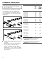
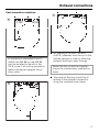
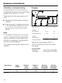
1
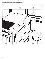
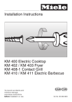
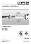
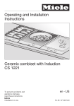
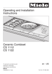
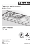
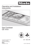
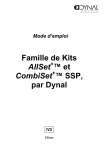
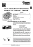
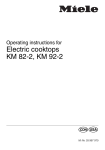
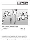
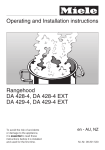
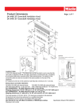
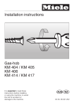
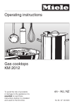
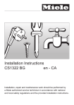
Operating instructions for the
DA 8-2 Extractor
]ö
M.-Nr. 03 997 810
Description of the appliance
Description of the appliance
1
6
2
5
2
4
3
Description of the appliance
Description of the appliance
The DA-8 Extractor draws cooking vapors in through the grease filter c and
exhausts them to the outside.
b Ventilation grill
c Grease filter
d 5’’ (120 mm) diameter exhaust
Data plate
Because the data plate is no longer
visible once the appliance has been installed, a 2nd data plate is supplied. It
should be placed into the space provided on page 11 of these instructions.
connection
e Extraction warning label
f Control knob
g Control panel
Do not install the DA 8-2 directly
next to a gas hob.
3
Help protect our environment
Help protect our environment
Disposal of packaging
The transport and protective packing is
mostly manufactured from the following
re-usable materials:
. . . Corrugated paper / cardboard mostly from recycled materials.
. . . Polyethylene foil (PE) partly from secondary raw materials.
Rather than throwing these materials
away, please take them to the nearest
recycling center for specific waste.
4
Disposal of your old machine
Old machines contain materials which
can be recycled. Please contact your
local recycling center or scrap merchant about potential recycling programs, before disposing of the appliance.
Read the notes on page 8 before disposing of the appliance.
Contents
Contents
Description of the appliance . . . . . . . . . . . . . . . . . . . . . . . . . . . . . . . . . . . . . . . . . 2
Help protect our environment . . . . . . . . . . . . . . . . . . . . . . . . . . . . . . . . . . . . . . . . 4
Warning and safety instructions. . . . . . . . . . . . . . . . . . . . . . . . . . . . . . . . . . . . . . 6
Operation . . . . . . . . . . . . . . . . . . . . . . . . . . . . . . . . . . . . . . . . . . . . . . . . . . . . . . . . 9
Cleaning and care . . . . . . . . . . . . . . . . . . . . . . . . . . . . . . . . . . . . . . . . . . . . . . . . 10
After Sales Service. . . . . . . . . . . . . . . . . . . . . . . . . . . . . . . . . . . . . . . . . . . . . . . . 11
Electrical connection . . . . . . . . . . . . . . . . . . . . . . . . . . . . . . . . . . . . . . . . . . . . . 12
Appliance dimensions . . . . . . . . . . . . . . . . . . . . . . . . . . . . . . . . . . . . . . . . . . . . . 13
Installation instructions. . . . . . . . . . . . . . . . . . . . . . . . . . . . . . . . . . . . . . . . . . . . 14
Exhaust connection . . . . . . . . . . . . . . . . . . . . . . . . . . . . . . . . . . . . . . . . . . . . . . . 16
Exhaust connections . . . . . . . . . . . . . . . . . . . . . . . . . . . . . . . . . . . . . . . . . . . . . . 17
Warning and safety instructions
Warning and safety instructions
Before installation and before using
the appliance for the first time read
these operating instructions carefully to avoid the risk of accidents
and damage to the appliance.
The appliance is intended for domestic use only.
Do not let small children play with
the extractor or its controls.
This extractor meets all statutory
safety requirements.
The electrical safety of this appliance can only be guaranteed
when continuity is complete between
the appliance and an effective
grounding system. It is imperative that
this basic safety requirement is met. If
there is any doubt, have the electrical
system of the house checked by a
qualified electrician.
The manufacturer cannot be held responsible for damage caused by the
lack or inadequacy of an effective
grounding system.
Installation and repairs should only
be performed by qualified and
trained personnel. Repairs by unqualified personnel could be dangerous.
Do not connect the appliance to
the main electrical supply using an
extension cord. Extension cords do not
guarantee the required safety of the appliance.
6
Before servicing, disconnect the
power supply by removing the fuse
or tripping the circuit breaker. Grasp
the plug, not the cord, when unplugging from the wall.
Do not use an open flame beside
the extractor. When turned on, the
extractor could draw flames into the filter. Grease particles trapped in the filter will then present a fire hazard.
When the extractor is installed
beside a gas cooktop, ensure that
the burners being used are always
covered by a saucepan or pot.
Heat given off by the flames could
otherwise damage the extractor.
Warning and safety instructions
Warning and safety instructions
Never leave the unit unattended
when cooking with oil or fat. Very
hot oil can ignite and damage the extractor.
Try to prevent drops of soup,
sauce, etc., or residues from the
grease filter from finding their way into
the interior of the appliance.
Should this occur however, cleaning
should only be performed by the Miele
Service Department, since the fan casing will have to be taken completely
apart.
Do not use the extractor without
the grease filter in place.
Clean the grease filter regularly. An
over-greasy filter is a fire hazard.
Do not use a steam-cleaner to
clean the extractor.
The steam could penetrate to electrical
components and cause a short circuit.
For the installer and electrician
Ensure that the electrical connection in the house and the details on
the data plate correspond.
Do not install the extractor beside
appliances burning solid fuel.
All ducting, pipework and fittings
must be of non-flammable material.
The appliance must not be connected to a chimney or vent flue.
Neither should it be connected to ducting which ventilates rooms with fireplaces.
If exhaust air is to be vented into a
chimney or ventilation duct no
longer serving other purposes, seek
professional advice.
Ensure there is sufficient ventilation
in the room when the extractor is in
operation.
When using the extractor at the same
time as other heating appliances which
depend on the air in the room (e.g.
gas, oil or coal fired heaters, continuous flow or other water heater, gas
cooktop or gas oven), make certain
that ventillation is adequate as the extractor will remove air from the room,
which these heaters need for combustion.
In order to ensure safe operation, and
to prevent the exhaust gases of the
heating appliances from being drawn
into the room when the extractor and
heater are in operation simultaneously,
an underpressure of 0.06 psi (4pa) is
the maximum permissible in the room.
Ventilation can be maintained by air inlets in windows, doors and outside
walls, or by other means, such as ensuring that the extractor can only be
turned on when the heating appliance
is off and vice-versa.
Keep these operating instructions in
a safe place for future reference and
pass them on to future owners if applicable.
7
Warning and safety instructions
Warning and safety instructions
Disposal of an old appliance
Before disposing of an old appliance, cut the cable off the appliance as close to the housing as
possible. The plug and cord should be
disposed of and not used elsewhere in
the house (electric shock hazard).
Text highlighted in boxes is of particular importance, and should be
read in conjunction with the warning
and safety instructions.
8
Operation
Operation
Turn the extractor on before starting to
cook:
Turn the control knob f clockwise.
Select a power setting strong
enough to clear the air:
Setting 1 =
for normal operation.
Setting 2 =
for removing heavy cooking odors.
After cooking
Turn the control knob counter clockwise to ”0“.
9
Cleaning and care
Cleaning and care
Before cleaning the extractor disconnect it from the main electrical
supply (pull out the plug or trip the
circuit breaker).
Grease filter
A re-usable metal grease filter is used
to remove solid particles (oil, dust, etc.)
from kitchen vapors, preventing soiling
of the extractor fan.
The grease filter can be cleaned in a
dishwasher or by hand.
The grease filter should be cleaned
regularly to ensure trouble free operation of the extractor fan.
An over-greasy filter is a fire hazard.
Make sure that no particles from the
grease filter fall into the interior of
the appliance. If this does happen,
the Service Department will have to
be called to clean the appliance, as
the fan casing will need to be dismantled.
Loosen both screws on the grease filter and remove the drip tray.
Clean the grease filter, the ventilation
grill and the drip tray.
By hand: in a solution of hot water
and detergent using a nylon brush, or
In a dishwasher: the grease filter,
the ventilation grill and the drip tray
should be placed in the bottom basket. Ensure that the spray arm is not
obstructed.
When clean and dry, replace the drip
tray on the grease filter and re-install
it in the appliance.
Replace the ventilation grill.
Control panel / Control knob
The control panel and control knob
should be cleaned in a solution of hot
water and detergent and dried using a
soft cloth.
To remove the grease filter the ventilation grill (1) must be removed.
Carefully withdraw the grease filter
(2).
10
Do not use abrasive cleaning
agents as these will scratch the surface material.
After Sales Service
After Sales Service
In the event of problems you cannot
correct yourself, please contact
Your Miele Dealer
or
The address of the nearest Service Department is given on the back page.
When contacting the Service Department, please quote the Model and Serial No. of the appliance.
The Miele Service Department
Space for enclosed data plate
11
Electrical connection
Electrical connection
Electrical connection - CDN
The extractor is supplied with a 1.10 m
power supply cable ready for connection to a 120 VAC, 60 Hz supply.
The rated load is 110 W. Fuse rating is
10 A.
Caution:
Make sure the power supply is OFF
during installation.
Important
The wires of the power cord are colored as follows:
Green = ground
Black = live
White = neutral
WARNING
THIS APPLIANCE MUST BE
GROUNDED
Electrical connection - USA
The extractor is supplied with a 4 ft
cord ready for connection to a
120 VAC, 60 Hz power supply. Connection should be made in an appropriate
junction box.
The rated load is 110 W. Fuse rating is
10 A.
Important
The wires of the power cord are colorcoded as follows:
Green/Yellow = ground
Blue = neutral
Brown = live
As the colors of the wires in the power
supply cord of this appliance may not
correspond with the colors of the wires
in your junction box, proceed as follows:
The green and yellow wire must be connected to the ground wire.
The blue wire must be connected to the
neutral wire.
The brown wire must be connected to
the hot wire.
WARNING
THIS APPLIANCE MUST BE
GROUNDED
12
Appliance dimensions
Appliance dimensions
3 3/8"
20 3/16"
14 3/16"
19 5/16"
3 1/16"
13
Installation instructions
Installation instructions
Do not install the DA 8-2 directly
next to a gas hob.
This extractor is designed for installation between Combiset appliances.
It should always be installed between
two appliances, such as the grill and
deep fryer.
Depth
(in
mm)
Width
(= Dimension B)
(in mm)
490
490
490
490
490
265
558
851
1144
1437
490
490
490
560
1143
1728
One 2 zone
+ one 4 zone
490
851
Two 2 zone
+ one 4 zone
490
1143
Three 2 zone
+ one 4 zone
490
1437
One 2 zone
+ two 4 zone
490
1436
Two 2 zone
+ two 4 zone
490
1729
2 zone Combiset
1 combiset
2 combisets
3 combisets
4 combisets
5 combisets
4 zone Combiset
1 combisets
2 combisets
3 combisets
Combination
23/16˝
195/16˝
23/16˝
Prepare the countertop cut-out as illustrated.
Dimension ”B“ will vary depending
on how many combisets are installed. The following chart gives
dimension ”B“ for a variety of 2 zone
(ie KM 88-2) and 4 zone (ie KM 93-2)
combinations.
14
Extractor (e.g. DA 8-2)
For installation between two appliances:
- Dimension B increases by 90 mm.
For installation at the end of a combination:
- Dimension B increases by 98 mm.
Installation instructions
Installation instructions
Remove the ventilation grill and
grease filter.
Depth
(in
inches)
Width
(= Dimension B)
(in
inches)
19-5/16
19-5/16
19-5/16
19-5/16
19-5/16
10-7/16"
22"
33-1/2"
45-1/16"
56-9/16"
19-5/16
19-5/16
19-5/16
22-1/16"
45"
68-1/16"
One 2 zone
+ one 4 zone
19-5/16
33-1/2"
Two 2 zone
+ one 4 zone
19-5/16
45"
Three 2 zone
+ one 4 zone
19-5/16
56 -9/16"
One 2 zone
+ two 4 zone
19-5/16
56-1/2"
Replace the two frame-mounting
screws.
Two 2 zone
+ two 4 zone
19-5/16
68-1/16"
Install the control panel and control
knob.
2 zone Combiset
1 combiset
2 combisets
3 combisets
4 combisets
5 combisets
4 zone Combiset
1 combisets
2 combisets
3 combisets
Combination
Extractor (e.g. DA 8-2)
For installation between two appliances:
- Dimension B increases by 3-9/16".
For installation at the end of a combination:
- Dimension B increases by 3-7/8"
Unscrew the frame (2 screws) at the
front and remove.
Install the extractor into the cut-out,
from below the countertop, so that
the protruding front edge rests on
the countertop.
Raise the rear of the unit and place
the extractor mounting bracket on
the countertop.
Lower the extractor onto the bracket
and align the unit in the cut-out.
Replace the frame and screw it into
the countertop along with the rear
mounting bracket.
Secure the front of the unit by tightening the clamp from underneath the
countertop.
Connect the vent duct to the extractor, and connect the appliance to the
power supply.
When installing more than one combiset, a stainless steel spacer bar must
be placed between units. It is supplied
with its own installation instructions.
15
Exhaust connection
Exhaust connection
Please read the ”Warning and
Safety Instructions“ to avoid the
danger of toxic fumes.
The DA-8 extractor should be installed in accordance with local and
national building regulations.
The exhaust connection should be
made into a vent shaft or chimney that
is not in use, using non-flammable exhaust ducting to the outside by using a
wall vent kit. These kits are available
from the Miele Parts Department.
Installation should only be performed out by a suitably qualified
and trained person.
16
The exhaust ducting should be as
short and straight as possible.
The use of angled pipes should be
avoided, as this will reduce the air
flow of the extractor.
Only use ducting made of nonflammable material.
The exhaust ducting may be angled
either to the left, right or downwards.
If the ducting is run beneath the
cabinets it requires a toe kick height
of at least 5-15/16 ’’.
If the ducting is run horizontally, ensure that there is a gradient of at
least 1/8 ’’ per foot, so that condensation will not run into the appliance.
Exhaust connections
Exhaust connections
Vent connection variations
D
F
7 1/2"
5 1/8"
8 1/4"
In connection examples B and C,
neither the KM 88 nor the KM 89
can be installed to the left of the
DA 8, since it will not be possible to
place a container beneath the oil
drain valve.
E
13"
An opening of at least 135 mm
(5-5/16") diameter must be cut in the
kitchen cabinet in order to allow the
exhaust ducting to pass through.
Mount the fan so that the impeller
cannot be inadvertently reached by
hand.
The exhaust ducting should be attached to the exhaust connection
using the supplied hose clamp.
10 1/4"
5 1/2"
17
Exhaust connections
Exhaust connections
Calculation of exhaust ducting
Example
A pipe diameter of 5" should ensure
trouble-free extraction up to a total pipe
length of 5.4. meters (17 1/2 ft).
Determine the total pipe length as follows:
Measure the total length of ducting
needed.
Add the length of additional ducting
to this figure according to the number and type of bends (see table
below).
Note
If the exhaust ducting will run through
rooms, ceiling space etc. where there
may be variations in temperature the
problem of sweating or condensation
will have to be addressed.
The exhaust ducting may need to be insulated.
Wall vent (1)
1.1 m
43’’
Flexible
90° bend (2)
0.3 m
12’’
Flexible pipe (3)
1.0 m
39’’
Flexible
45° bend (4)
0.2 m
8’’
Total pipe length
2.6 m
81/2’’
With a total pipe length of 81/2 ft.
(102’’) the exhaust is within the effective range.
Air flow rates:
- Setting 1
- Setting 2
240 m3/h (145 CFM)
465 m3/h (275 CFM)
Type of bend
Angle
of bend
Radius of
bend
(in mm)
Radius of
bend
(in inches)
Effective
pipe length
(in meters)
Effective
pipe length
(in inches)
Flexible pipe
45°
90°
120
120
4 3/4
4 3/4
0.2
0.3
8’’
12’’
1.0
39’’
Wall vent
18
19
Alteration rights reserved / 22 / 001
CDN, USA - 4698