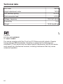
1
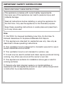
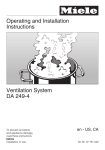
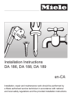
Operating and Installation Instructions Ventilation Hood To prevent accidents and damage to the appliance, you must read these instructions before installing the appliance and using it for the first time. en-US M.-Nr. 10 118 580 Contents IMPORTANT SAFETY INSTRUCTIONS................................................................. 4 Caring for the environment ................................................................................. 13 Description of functions ...................................................................................... 14 Con@ctivity 2.0 function ........................................................................................ 15 Guide to the appliance......................................................................................... 16 Operation (Automatic mode)............................................................................... 18 Cooking with Con@ctivity 2.0 (Automatic mode)................................................... 18 Temporarily exiting Automatic mode ..................................................................... 20 Resuming Automatic mode ................................................................................... 20 Operation (Manual mode).................................................................................... 21 Cooking without Con@ctivity 2.0 (Manual mode) .................................................. 21 Turning on the fan .................................................................................................. 21 Selecting the power level....................................................................................... 21 Selecting the Delayed shut down time .................................................................. 21 Turning off the fan .................................................................................................. 21 Dimming and turning the overhead lighting on/off ................................................ 22 Power management ............................................................................................... 22 Operation (Automatic and Manual modes)........................................................ 23 Filter saturation indicator ....................................................................................... 23 Adjusting the filter saturation indicator for grease filters .................................. 23 Checking the filter saturation indicator ............................................................. 24 Adjusting the height of the canopy ........................................................................ 24 Cleaning and care ................................................................................................ 25 Stainless steel housing .......................................................................................... 25 Grease filters .......................................................................................................... 26 Installation ............................................................................................................ 29 Before installation .................................................................................................. 29 Installation parts..................................................................................................... 29 Appliance dimensions............................................................................................ 30 Distance between cooktop and ventilation hood (S) ............................................. 31 Installation recommendations................................................................................ 32 Structural support .................................................................................................. 32 Removing the protective film ................................................................................. 32 Exhaust duct......................................................................................................... 42 Condensate trap .................................................................................................... 43 2 Contents Electrical connection ........................................................................................... 44 Grounding Instructions .......................................................................................... 44 Activating Con@ctivity 2.0 ................................................................................... 45 Installation of the Con@ctivity 2.0 stick ................................................................. 45 Activating the Con@ctivity 2.0 function ................................................................. 45 Activating the ventilation hood ......................................................................... 45 Activating the cooktop...................................................................................... 46 Activation failed ................................................................................................ 46 Deactivating Con@ctivity 2.0 ................................................................................. 46 Service and warranty ........................................................................................... 47 Location of the data plate ...................................................................................... 47 Technical data ..................................................................................................... 48 3 IMPORTANT SAFETY INSTRUCTIONS READ AND SAVE THESE INSTRUCTIONS This appliance complies with current safety requirements. Improper use of the appliance can lead to personal injury and material damage. Read all instructions before installing or using the appliance for the first time. Only use the appliance for its intended purpose. Keep these operating instructions in a safe place and pass them on to any future user. Use CAUTION: For General Ventilating Use Only. Do Not Use To Exhaust Hazardous Or Explosive Materials And Vapors. This appliance is intended for residential use only. Use only as described in these operating instructions. This ventilation hood is designed for domestic use and for use in similar residential environments. This ventilation hood is not intended for outdoor use. It must only be used to extract and clean vapors produced during cooking. Any other use occurs at the owner's own risk. This appliance is suitable for installation above gas or electric cooking surfaces. Persons who lack physical, sensory or mental abilities, or experience with the appliance should not use it without supervision or instruction by a responsible person. 4 IMPORTANT SAFETY INSTRUCTIONS Children As with any appliance, close supervision is necessary when used by children. Please supervise children in the vicinity of the hood and do not let them play with it. Danger of suffocation! Ensure that any plastic wrappings, bags, etc. are disposed of safely and kept out of the reach of children. 5 IMPORTANT SAFETY INSTRUCTIONS Technical safety WARNING: TO REDUCE THE RISK OF FIRE, ELECTRIC SHOCK, OR INJURY TO PERSONS, OBSERVE THE FOLLOWING: – Use this appliance only in the manner intended by the manufacturer. If you have questions, contact Miele. – Before servicing or cleaning the appliance, switch power off at the service panel and lock the service disconnecting means to prevent power from being switched on accidentally. If the service disconnecting means cannot be locked, securely fasten a prominent warning device, such as a tag, to the service panel. Installation, repair and maintenance work should be performed by a Miele authorized service technician in accordance with national and local safety regulations and the provided installation instructions. Contact Miele’s Technical Service Department for examination, repair or adjustment. Repairs and other work by unauthorized persons could be dangerous and may void the warranty. A damaged ventilation hood oven can be dangerous. Always check for visible signs of damage. Never use a damaged ventilation hood. Be certain your appliance is properly installed and grounded by a qualified technician. To guarantee the electrical safety of this appliance, continuity must exist between the appliance and an effective grounding system. It is imperative that this basic safety requirement be met. If there is any doubt, have the electrical system of the house checked by a qualified electrician. Reliable and safe operation of this hood can only be guaranteed if it has been connected to the electrical supply. To avoid damaging the ventilation hood, make sure that the connection data (voltage and frequency) on the data plate correspond to the building's power supply before connecting the appliance. When in doubt, consult a qualified electrician. 6 IMPORTANT SAFETY INSTRUCTIONS Do not use a power bar or extension cord to connect the ventilation hood to electricity. These are a fire hazard and do not guarantee the required level of appliance safety. To ensure safe operation, only use the ventilation hood after it has been properly installed. This ventilation hood may not be used in non-stationary locations (e.g. on a ship). Adequate ventilation must be provided when the hood is operated simultaneously with devices that burn gas or other fuels. Only open the housing as described in the enclosed "Installation diagram" and in the "Cleaning and care" section of this manual. Under no circumstances should any other parts of the housing be opened. Tampering with electrical connections or components and mechanical parts is highly dangerous to the user and can cause operation faults. Defective components should be replaced by Miele original parts only. Only with these parts can the manufacturer guarantee the safety of the appliance. During installation, maintenance, and repair work, the ventilation hood must be disconnected from the electrical supply. It is only completely isolated from the electricity supply if one of the following applies: – The circuit breakers on the electrical service panel are tripped. – The screw-type fuses on the electrical service panel have been removed. – The power cable (if present) has been unplugged from the socket (pull the plug not the cord). 7 IMPORTANT SAFETY INSTRUCTIONS Proper use WARNING: TO REDUCE THE RISK OF A COOKTOP GREASE FIRE: – a) Never leave surface units unattended at high settings. Boilovers cause smoking and greasy spillovers may ignite. Heat oils slowly on low or medium settings. – b) Always turn the hood on when cooking at a high heat. – c) Clean the ventilation hood frequently. Grease should not be allowed to accumulate on the fan or filter. – d) Use the proper pan size. Always use cookware appropriate for the size of the cooking area. Never use an open flame beneath the ventilation hood. To avoid the risk of fire, do not flambé or grill over an open flame. When turned on, the ventilation hood will draw any flames into the filter. Fat deposits may ignite. WARNING: TO REDUCE THE RISK OF INJURY TO PERSONS IN THE EVENT OF A COOKTOP GREASE FIRE, OBSERVE THE FOLLOWING*: – a) SMOTHER FLAMES with a close fitting lid, cookie sheet, or metal tray then turn off the burner. BE CAREFUL TO PREVENT BURNS. If the flames do not go out immediately, EVACUATE AND CALL THE FIRE DEPARTMENT. – b) NEVER PICK UP A FLAMING PAN - You may be burned. – c) DO NOT USE WATER, including wet dishcloths or towels - a violent steam explosion will result. – d) Use a fire extinguisher ONLY if: – 1) You have a class ABC extinguisher, and you know how to operate it. – 2) The fire is small and contained in the area where it started. – 3) The fire department is being called. – 4) You can fight the fire with your back to an exit. *Based on "Kitchen Firesafety Tips" published by NFPA. 8 IMPORTANT SAFETY INSTRUCTIONS The ventilation hood may become damaged if exposed to excessive heat from a gas cooktop. – When using the ventilation hood over a gas cooktop, ensure that any burners in use are always covered by cookware. Turn burners off when removing the cookware, even if doing so for just a short time. – Select cookware that is suitable for the size of the burner. – Adjust the flame so that it never extends up the sides of the cookware. – Avoid overheating the cookware (e.g., when cooking with a wok). Always turn the ventilation hood on whenever a burner is in use to prevent damage from condensation. Overheated oils and fats can ignite and set the ventilation hood on fire. When cooking with oils or fats, do not leave pots, pans or fryers unattended. Never leave an electric grill unattended when grilling. Fat and debris deposits impair the proper functioning of the ventilation hood. To ensure that cooking vapors are properly cleaned, never use the ventilation hood without the grease filters in place. There is a risk of fire if cleaning is not completed according to the instructions in this manual. Please note that the heat rising from the stovetop during cooking can cause the ventilation hood to become very hot. Do not touch the housing or the grease filters until the ventilation hood has cooled down. 9 IMPORTANT SAFETY INSTRUCTIONS Proper installation WARNING: TO REDUCE THE RISK OF FIRE, ELECTRIC SHOCK, OR INJURY TO PERSONS, OBSERVE THE FOLLOWING: – a) Installation work and electrical wiring must be done by qualified person(s) in accordance with all applicable codes and standards, including fire-rated construction. – b) Sufficient air is needed for combustion and exhausting of gases through the flue (chimney of fuel burning equipment to prevent back drafting. Follow the heating equipment manufacturer’s guideline and safety standards such as those published by the National Fire Protection Association (NFPA) and the American Society for Heating, Refrigeration and Air Conditioning Engineers (ASHRAE), and the local code authorities. – c) When cutting or drilling into the wall or ceiling, do not damage electrical wiring and other hidden utilities. – d) Ducted hoods must always be vented to the outdoors. – e) Do not use this hood with any solid-state speed control device. To determine whether a ventilation hood may be operated above your cooking appliance, please refer to the information provided by the appliance's manufacturer. Safety regulations prohibit the installation of a ventilation hood above solid fuel stoves. Insufficient distance between the cooking appliance and the ventilation hood can result in damage to the hood. The minimum safety distances between the appliance and the bottom of the ventilation hood specified in the "Installation" section must be maintained, unless the appliance's manufacturer has indicated that a greater distance is required. If more than one cooking appliance is used beneath the ventilation hood, and if different minimum safety distances apply for these appliances, you should use the greater distance. 10 IMPORTANT SAFETY INSTRUCTIONS Be sure to observe the information contained in the "Installation" section when mounting the ventilation hood. Metal parts can have sharp edges which may cause injury. Wear gloves to protect your hands from being cut. When installing the exhaust duct, only use pipes or tubes made of non-flammable material. These can be obtained from your Miele dealer or from Miele Technical Service. Exhaust air should not be vented into a chimney or vent flue which is otherwise in use and should not be channeled into ducting which ventilates rooms with fuel-burning installations. If exhaust air is to be extracted into a chimney or vent flue no longer used for other purposes, be sure to comply with all applicable regulations. WARNING: TO REDUCE THE RISK OF FIRE USE ONLY METAL DUCTWORK. Cleaning and care Never use a steam cleaner to clean the ventilation hood. The steam can reach the electrical components and cause a short circuit. Accessories Use only genuine original Miele parts. If parts or accessories from other manufacturers are used, the warranty will become void. 11 IMPORTANT SAFETY INSTRUCTIONS FCC Declaration of Conformity These devices comply with FCC Rules Part 15. This equipment has been tested and found to be in compliance with the limits for a Class B digital device, pursuant to Part 15 of the FCC Rules of Operation and is subject to the following conditions: These devices may not cause harmful interference. These devices must accept any interference received, including interference that may cause undesired operation. FCC Radiation Exposure Statement This equipment complies with FCC radiation exposure limits set forth for an uncontrolled environment. This equipment should be installed and operated with minimum distance 8" (20 cm) between the radiator and your body. Industry Canada Statement This digital apparatus does not exceed the Class B limits for Radio Noise Emissions from digital apparatus set out in the Radio Interference Regulations of the Canadian Department of Communications. Complies with Canadian ICES-003 Class B specifications. 12 Caring for the environment Disposal of the packing material The cardboard box and packing materials protect the appliance during shipping. They have been designed to be biodegradable and recyclable. Ensure that any plastic wrappings, bags, etc. are disposed of safely and kept out of the reach of children. Danger of suffocation! Disposal of your old appliance Do not dispose of this appliance with your household waste. Old appliances may contain materials that can be recycled. Please contact your local recycling authority about the possibility of recycling these materials. Before discarding an old appliance ensure that it presents no danger to children while being stored for disposal. Unplug it from the outlet, cut off its power cord and remove any doors to prevent hazards. 13 Description of functions The following functions are available on your ventilation hood, depending on the model: Vented mode The air is drawn in and cleaned by the grease filters and directed outside. Non-return flap A non-return flap in the ducting prevents the exchange of inside and outside air from occurring when the ventilation hood is not in use. The flap is closed when the ventilation hood is turned off. When the ventilation hood is turned on, the non-return flap opens so that the exhaust air can be transported outside without any obstruction. A non-return flap has been provided with the hood in case your ducting does not have one. It is inserted into the outlet duct collar of the fan. 14 Description of functions Con@ctivity 2.0 function Automatic control This hood features a communication function which enables the automatic control of the hood based on the operational status of a Miele induction cooktop. The cooktop transmits information about its operational status to the hood using a radio signal. – When a burner is turned on, the cooktop lighting on the hood turns on automatically. After a brief delay, the ventilation hood fan also comes on. – During cooking, the hood automatically selects the fan level based on the number of burners in operation and their power levels. – Once you have turned off the cooktop, the fan and the lighting will turn off automatically after a predetermined delay. Detailed information about this function can be found under "Operation." To enable the communication function, the cooktop must be equipped with the corresponding Con@ctivity 2.0 stick . Please refer to the installation instructions for the Con@ctivity 2.0 stick to determine whether connection to your cooktop is possible. There must be radio contact between the cooktop and the hood for you to be able to use the Con@ctivity 2.0 function (see "Activating Con@ctivity 2.0"). 15 Guide to the appliance 1 2 3 IS 16 5 15 Guide to the appliance a Telescopic chimney b Chimney c Height-adjustable canopy d Control panel e Grease filters f Spacer frame The spacer frame creates a shadow gap between the chimney and the ceiling. The hood can be installed with or without the spacer frame. g Overhead lighting h Overhead lighting button i On/Off button for fan j Fan power selection k Delayed shut down button l Operating hours button m Controls for raising and lowering the canopy 17 Operation (Automatic mode) When Con@ctivity 2.0 is active, the hood always operates in Automatic mode (see "Activating Con@ctivity 2.0"). See "Cooking without Con@ctivity 2.0" for information on manually operating the hood. Cooking with Con@ctivity 2.0 (Automatic mode) Turn on a burner to the desired power setting. The hood lighting will come on. After a few seconds, the fan will come on, briefly operating at power level 2 before immediately switching to level 1. The hood selects the fan level automatically during cooking. This level is determined by the total output of the cooktop, i.e. the number of burners in operation and the power settings selected. If you select a higher power setting on the cooktop or switch on multiple burners, the hood will switch to a higher fan level. If you select a lower power setting on the cooktop or turn off a burner, the hood will accordingly switch to a lower fan level. Examples for fan levels 1 to 4 18 Reaction time Changing the power setting on the cooktop does not lead to an immediate increase or decrease in cooking vapors. For this reason, the hood reacts with a slight delay. Delays can also result from the fact that the cooktop transmits the information to the hood in intervals. The reaction time can vary from a few seconds to a couple of minutes. Operation (Automatic mode) Cooking process Turning off If, for example, you switch on a burner at the highest power setting to heat cookware in preparation for searing and then reduce the power level after approx. 60 to 90 seconds, a cooking process is recognized. Turn off all burners. The hood turns on automatically and, after the cooktop power level has been reduced, switches back to fan level 3, where it remains for approx. 5 minutes. After this, the fan level is once again determined by the Con@ctivity function. You can also manually select a different fan level before then. Over the next few minutes, the ventilation hood fan setting will decrease one level at a time until the hood eventually turns off. This helps to neutralize any lingering vapors and odors in the air. – From the intensive setting IS, the fan immediately switches to level 3. – If the fan is operating at level 3, it will switch to level 2 after approx. 1 minute. – From level 2, the fan switches to level 1 after 2 minutes. – After 2 minutes at level 1, the fan automatically turns off. – After another 30 seconds, the lighting turns off. The cooking process is now finished. 19 Operation (Automatic mode) Temporarily exiting Automatic mode To temporarily exit the Automatic mode when cooking: Manually select a different fan level, or Manually turn the hood off, or Activate the Delayed shut down function on the ventilation hood. The fan turns off after the delay time selected, and the lighting will remain on. The ventilation hood functions can now be operated manually (see "Cooking without Con@ctivity 2.0"). 20 Resuming Automatic mode The ventilation hood resumes Automatic mode: If the ventilation hood has not been used for a period of approx. 5 minutes after the manual selection of a fan level, or If the manually selected fan level once again matches the automatic setting, or If the ventilation hood fan and the cooktop have been turned off for at least 30 seconds. Automatic mode will resume the next time the cooktop is turned on. If you wish to manually operate the ventilation hood for a complete cooking process, turn on the ventilation hood fan before turning on the cooktop. If the ventilation hood and the cooktop have been turned off for at least 30 seconds after you have finished cooking, Automatic mode will resume the next time the cooktop is turned on. Operation (Manual mode) Cooking without Con@ctivity 2.0 (Manual mode) Selecting the Delayed shut down time The hood can be operated manually if: It is a good idea to let the fan run for a few more minutes after cooking in order to neutralize any lingering vapors and odors in the air. With the Delayed shut down function, it is possible to have the fan automatically shut off after a predetermined period of time. – The Con@ctivity 2.0 function is not activated. – You have temporarily deactivated the Con@ctivity 2.0 function (see "Temporarily exiting Automatic mode"). Turning on the fan Press the On/Off button . The fan turns on at level 2. The symbol and 2 will light up in the fan level display. Selecting the power level Power levels 1 to 3 can be used for light to heavy cooking vapors and odors. After you have finished cooking, press the Delayed shut down button 5 15 – Once: fan turns off after 5 minutes (5 lights up). – Twice: fan turns off after 15 minutes (15 lights up). – If you press the Delayed shut down button 515 again, the fan remains turned on (515 goes out). For strong vapors and odors that are temporarily produced when cooking, e.g. during searing, select the IS level as an intensive setting. Turning off the fan Press the "" button for a lower power level or the "" button to select a higher level. The symbol will go out. Press the On/Off button to turn the fan off. Reducing power of the intensive setting If power management is activated (default setting), the fan automatically switches back to level 3 after 5 minutes. 21 Operation (Manual mode) Dimming and turning the overhead lighting on/off Turning power management on/off The overhead lighting can be switched on and off and dimmed independently of the fan. Press the delayed shut down button 5 15 for approx. 10 seconds until 1 appears in the fan level display. Press the lighting button briefly to turn it on or off. Then, press the following buttons in order: The lighting will turn on at maximum brightness. – The lighting button , Press and hold in the lighting button . The brightness will gradually dim until you release the button. – The lighting button again. Turn off the fan and the lighting. – Followed by the "" button and then Press and hold in the lighting button again to increase the brightness to the level required and then release it. If power management is turned on, the 1 and IS indicators will be continuously lit. If it is turned off, 1 and IS will flash. Power management Press the "" button to turn power management off. The ventilation hood features a power management system to help save energy. The fan power level is reduced and the lighting is turned off automatically. – If the intensive setting is selected, the fan automatically turns to level 3 after 5 minutes. – If the fan is set to level 3, 2 or 1, it switches to the next-highest fan setting after 2 hours and then in 30minute intervals until the fan eventually switches off. – If the overhead lighting is on, it automatically turns off after 12 hours. 22 The 1 and IS indicators will flash. To turn it on, press the "" button. The 1 and IS indicators are constantly lit. Confirm the setting by pressing the delayed shut down button 5 15. All the indicator lights will go out. If the setting is not confirmed within 4 minutes, the old setting is retained. Operation (Automatic and Manual modes) Filter saturation indicator The number of hours the hood has been in operation is stored in appliance memory. When the grease filter symbol , lights up, the filter saturation indicator is signaling that the filters need to be cleaned or changed. Additional information about cleaning and changing the filters and resetting the filter saturation indicator can be found under "Cleaning and care." Adjusting the filter saturation indicator for grease filters You can set the filter saturation indicator to suit your cooking habits. The factory default setting is an interval of 30 hours. Fan power level indicators 1 to IS show the current time setting: Indicator 1................................ 20 hours Indicator 2................................ 30 hours Indicator 3................................ 40 hours Indicator IS .............................. 50 hours Press the "" symbol for a shorter operating time, or the "" symbol to select a longer operating time. Confirm the selection by pressing the filter saturation indicator . All the indicator lights will go out. If the setting is not confirmed within 4 minutes, the ventilation hood automatically reverts to the old setting. – Select a shorter time (20 hours) if you often fry foods. – We also recommend a shorter cleaning interval if you only cook occasionally. This will prevent grease buildup from hardening and making cleaning more difficult. – Select a longer cleaning interval of 40 or 50 hours if you use very little fat when cooking. Press the On/Off button to turn the fan off. Press the Delayed shut down button 515 and the filter saturation button at the same time. The grease filter symbol on the filter saturation button and one of the fan power level indicators will flash. 23 Operation (Automatic and Manual modes) Checking the filter saturation indicator Before the set operating time has run out, you can check what percentage of the time has elapsed. Press the On/Off button to turn the fan on. Press and hold the operating hours button : The grease filter symbol lights up. One or more of the fan power level indicators will flash simultaneously. The number of flashing indicators shows the elapsed operating hours as a percentage. Indicator 1 ..................................... 25% Indicators 1 and 2 ......................... 50% Indicators 1 to 3 ............................ 75% Indicators 1 to IS ......................... 100% The elapsed operating hours remain stored in the memory when the hood is turned off or if power to the appliance is lost. 24 Adjusting the height of the canopy The height adjustment feature on the canopy can be used to: – adapt the height of the hood to suit the installation conditions. – adjust the working area underneath the hood to the height of the user. – maximize steam extraction by lowering the steam during particularly intensive cooking. – create more working space above the cooktop by raising the canopy when required. The canopy can be raised or lowered by pressing the controls briefly. Pressing one of the controls again stops the canopy. If it is not stopped, the canopy will automatically be raised or lowered to its fullest extent. Repeated use of the height adjustment feature over several minutes will cause it to cut out. It can be used again after a pause. Cleaning and care Stainless steel housing General The surfaces and control buttons are susceptible to scratching and chipping. Observe the following cleaning instructions. Clean all surfaces and control buttons using warm water and liquid dish soap only, applying the mixture with a sponge cloth. Make sure that no water gets into the interior of the hood. Only use a damp cloth to clean the hood, especially in the control panel area. After cleaning, dry the surfaces with a soft cloth. Avoid the following: – Cleaners containing soda, acid or chloride, or cleaners containing solvents Special instructions for stainless steel surfaces (does not apply to control buttons) Stainless steel surfaces can also be cleaned using a non-abrasive stainless steel cleaner, available from Miele. To prevent the surfaces from quickly becoming dirty again, we recommend treating them with a stainless steel care conditioner. Apply sparingly over the entire area using a soft cloth. Special instructions for RAL color finish housing (special order) Observe the general cleaning instructions contained in this chapter. Minor scratches on the surface are inevitable when cleaning the housing. Depending on the lighting in the kitchen, this may negatively affect the appliance's appearance. – Abrasive cleaners such as scouring powder, scouring liquid, abrasive sponges such as pot scourers, or used sponges that still contain residues from abrasive cleaners 25 Cleaning and care Important for the controls Do not leave dirt and debris on the buttons for any length of time. Otherwise they may become discolored or damaged. Remove any dirt or debris immediately. Observe the general cleaning instructions contained in this chapter. Do not use a stainless steel cleaner to clean the control buttons. Grease filters The reusable metal grease filters in the appliance remove the solid particles contained in kitchen vapors (fat, dust, etc.), thereby preventing the ventilation hood from becoming dirty. A dirty filter is a fire hazard! Cleaning intervals Over longer periods of time, fat buildup on the grease filter hardens and makes cleaning more difficult. Therefore, we recommend cleaning the grease filters once every 3-4 weeks. By illuminating the grease filter symbol, the filter saturation counter reminds you to regularly clean the grease filters. You can adjust the interval of the filter saturation counter to match your cooking habits (see "Operation"). Removing the grease filters When handling a grease filter, be careful not to drop it. This can result in damage to the filter and to the cooktop. Make sure you hold the filter securely at all times when handling it. 26 Cleaning and care Cleaning the grease filters in the dishwasher Place the filters as upright or inclined as possible in the lower basket. Ensure that the spray arm is not obstructed. To remove a grease filter, release the locking clip. Then, open the filter to a 45° angle, unhook it, and remove it from the hood. Cleaning the grease filters by hand Clean the filters with a soft nylon brush in a mild solution of hot water and dish soap. Do not use undiluted dish soap. Unsuitable cleaning agents Unsuitable cleaners can cause damage to the filter surfaces if used regularly. Do not use any of the following: Use a common household dishwasher detergent. Select a program with a wash temperature between 122°F (50°C) and 149°F (65°C). In a Miele dishwasher use the "Normal" program. Depending on the detergent used, cleaning the filters in a dishwasher may cause the inside filter surfaces to become discolored. However, this will not affect the functioning of the filters in any way. – Lime removers – Abrasive powders or abrasive liquids – Aggressive all-purpose cleaners and degreaser sprays – Oven sprays 27 Cleaning and care After cleaning After cleaning, leave the filters on an absorbent surface to dry. When removing the filters for cleaning, also clean off any accessible oil or fat buildup from the housing. Doing so will prevent a fire hazard. Reinstall the grease filters. When inserting the filters, make sure that the locking clip is facing down. If the filters have been installed incorrectly, you can insert a small screwdriver into the slit to disengage the locking clip. Resetting the filter saturation counter for the grease filters Once cleaning is complete, the filter saturation counter must be reset. While the fan is turned on, press the filter saturation indicator for approx. 3 seconds until 1 is the only indicator flashing. The grease filter symbol goes out. When cleaning the grease filters before the full operating time has elapsed: Press the filter saturation indicator for approx. 6 seconds until 1 is the only indicator flashing. 28 Installation Before installation Before installing the appliance, read all of the information contained in this chapter and also in the "IMPORTANT SAFETY INSTRUCTIONS" section. 4 telescopic extension piece holders for aligning and securing the telescopic chimney Installation parts 4 screws M³/₁₆" x ⁵/₁₆" (M4 x 8.5 mm) for securing the telescopic extension piece holders. 4 screws, 6 ⁹/₁₆" x 4 ⁵/₁₆" (7 x 110 mm) and 4 plugs, ³/₈" x 3 ¹/₈" (10 x 80 mm) for securing the hood to the ceiling. The screws and plugs are designed for use in solid ceilings only. The plugs must only be used together with the included 6 9/16" x 4 5/16" (7 x 110 mm) screws. For other types of ceiling construction, alternative fixings will be required. Make sure the ceiling is able to take the weight of the hood. 14 screws M³/₁₆" x ⁵/₁₆" (M4 x 8 mm) for securing the spacer frame and securing the hood to the installation frame. 1 screw M³/₁₆" x ⁵/₈" (M4 x 16 mm) for securing the chimney. 29 Installation Appliance dimensions a Mounting area for the exhaust ducting and power cable. In recirculation mode, only the power cord is required. b Alternative installation with spacer frame c A power cord is required to connect the hood to the outlet in the ceiling. With extraction mode flexible ducting is also required. Exhaust connection 6" (150 mm) 30 Installation Distance between cooktop and ventilation hood (S) Provided a larger distance is not given by the manufacturer of the cooktop, follow the minimum safety distances between a cooktop and the bottom of the hood. Please also observe the information contained in the "IMPORTANT SAFETY INSTRUCTIONS" section. Minimum distance S Cooking appliance Miele range Non-Miele range Electric Cooktops 24" (610 mm) Electric Barbeques and Fryers 26" (660 mm) Multiburner Gas Cooktops ≤ 43,000 BTU/hr (12.6 W), no burner > 15,000 BTU/hr (4.5 kW). 26" (660 mm) 30" (760 mm) Multiburner Gas Cooktops ≤ 73,800 BTU/hr (21.6 W), no burner > 16,500 BTU/hr (4.8 kW) 30" (760 mm) Multiburner Gas Cooktops > 73,800 BTU/hr (21.6 W), or one of the burners > 16,500 BTU/hr (4.8 kW) Not possible Single Burner Gas Cooktops ≤ 20,500 BTU/hr (6 kW) 26" (660 mm) 30" (760 mm) Single Burner Gas Cooktops > 20,500 BTU/hr (6 kW) ≤ 27,600 BTU/hr (8.1 kW) 30" (760 mm) Single Burner Gas Cooktops > 27,600 BTU/hr (8.1 kW) Not possible The fully lowered canopy must not go below the minimum distances given. The height range for the appliance can be extended or limited by moving the limit switch (see "Installation"). 31 Installation Installation recommendations Structural support – When selecting an installation height, always take the user height into consideration. Users should have ample space to work comfortably on the cooktop and reach the ventilation hood controls with ease. – Please note that the greater the distance from the cooktop, the less effective the hood is at drawing in the cooking vapors. – To achieve optimal vapor extraction, make sure that the hood covers the cooktop. The hood should be positioned centrally over the cooktop, not to the side or rear. – The cooktop should be no wider than the hood. Preferably, it should be narrower. – The mounting area must be easily accessible. The ventilation hood should be easy to reach and disassemble in case a service call is necessary. This should be taken into consideration when planning the position of cupboards, shelves, ceilings or decorative elements in the vicinity of the ventilation hood. The hood must be attached to rigid structural framing that is supported in its entirety by the ceiling joists, or to the ceiling joists directly. Do not attach the plate directly to the ceiling with anchors, toggle bolts, etc. Removing the protective film The housing components are covered by a protective film to prevent them from becoming damaged during transport. Please remove this film before installing the housing components. It can be peeled off easily without any additional tools. 32 Installation 85 5/8" m 22 /8" 0 8 m 22 0 mm For vented mode: dai3435aus Draw two intersecting lines on the ceiling. – Place a section of the exhaust ducting in the ceiling and feed it down through the cross-sectional area as illustrated. Exhaust ducting of approx. 8" (200 mm) length is required between the ceiling and the hood exhaust socket. – Secure the exhaust ducting to the exhaust socket, e.g. with a hose clip (available as an optional accessory) on flexible ducting. Place the power cord and guide it through the ceiling in the area shown. A power cord approx. 12" (300 mm) in length is required between the ceiling and the hood connectors. 33 Installation Use a knife to release the four spacers and the two covers from the spacer frame supplied. Drill four holes ³/₈" (10 mm), approx. 4 ¹/₂" (115 mm) deep for the plugs supplied. Use the spacer frame as a drilling template. Place it on the ceiling with the arrows pointing forwards. Using the notches, align the spacer frame on the intersecting lines and make pencil marks for the drill holes. 34 Place the four plugs in the holes and screw in the four screws so that they protrude by approx. 1 ³/₁₆" (30 mm). Installation Loosen the two telescopic extension piece holders from the installation frame. The spacer frame can be installed between the chimney and the ceiling. This creates a shadow which gives the illusion of a gap between the ceiling and the chimney. This is useful if the ceiling is not level or is uneven. The hood is aligned vertically with the spacers supplied. Visual irregularities between the chimney and the ceiling are then concealed by the shadow. If you wish to install the hood with the spacer frame, remove the four inserts from the fixing holes. 35 Installation Mount the spacer frame onto the installation frame. Hang the hood on the four screws, making sure the controls are at the front. If using the spacer frame, place the two covers into the fixing holes. 36 Installation Place the exhaust ducting onto the exhaust socket. Connect the power cord. See "Electrical connection." Align the installation frame and secure it with the screws. The spacers, which were removed from the spacer frame at the start, can be used to align the hood vertically. 37 Installation Remove the grease filters from the hood. Push the tower and the telescopic extension piece upwards and bend the retaining tabs outwards again to prevent the tower and telescopic extension piece from slipping down again. Remove the safety screw for the tower on the inside of the frame. 38 Installation When the canopy is lowered, the safety distance to the cooker may not be exceeded (see "Appliance dimensions"). The height range for the appliance can be extended or limited by moving the limit switch. Press the button. The canopy will be lowered to its fullest extent. Check the distance to the cooker. If the safety distance is undershot, the limit switch must be readjusted. Fit the four telescopic extension piece holders between the tower and the telescopic extension piece. The internal telescopic extension piece rests on the clamps. When the screws are tightened, the telescopic extension piece holders spread out and push the telescopic extension piece upwards. Loosen the top limit switch. Tighten the screws only until the top edge of the telescopic extension piece is evenly aligned with the ceiling or the spacer frame. 39 Installation Move the canopy to the required height by pressing the button and stop it by pressing the or button. Screw on the limit switch opposite the guide. Hold the chimney securely, bend back the retaining tabs and carefully lower it. The chimney will locate in the cut-out in the canopy. 40 Installation 1x T20 M4x16 Insert the safety screw on the inside. Carefully remove the protective foil from the grease filters. Reinsert the grease filters. 41 Exhaust duct WARNING: Danger of toxic fumes. Gas cooking appliances release carbon monoxide that can be harmful or fatal if inhaled. To reduce the risk of fire and to properly exhaust air, the exhaust gases extracted by the hood should be vented outside of the building only. Do not vent exhaust air into spaces within walls or ceilings or in attics, crawl spaces or garages. To reduce the risk of fire, only use metal ductwork. Please read and follow the "IMPORTANT SAFETY INSTRUCTIONS" to reduce the risk of personal injury. Follow all local building codes when installing the hood. Only use smooth pipes or flexible duct hoses made from nonflammable materials for exhaust ductwork. To achieve the greatest possible air extraction with the lowest noise levels, please note the following: – The diameter of the exhaust duct should not be less than 6" (150 mm). – If flat exhaust ducts are used, the cross section should not be smaller than that of the exhaust connector. – The exhaust duct should be as short and straight as possible. – If elbows are needed, make sure they have a large radius. – The exhaust duct itself must not be kinked or compressed. 42 – Make sure that all connections are secure and airtight. Remember that any constriction of the airflow will reduce extraction performance and increase operating noise. If the exhaust duct is to be routed through an outside wall, we recommend installing a telescopic wall vent or a rooftop vent (available as an optional accessory). If the exhaust air is to be conducted into a vent flue, the intake piece must be aligned with the flow direction of the flue. When installing the exhaust duct horizontally, you must slope it away from the source by at least ³/₈" per 3 ³/₈" (1 cm per meter). This ensures that condensate cannot drain back into the ventilation hood. If the exhaust duct is to be routed through rooms, ceiling space etc., the temperatures in these different areas may differ greatly, which means that the problem of condensation will need to be addressed. The exhaust duct will need to be insulated. Exhaust duct Condensate trap In addition to insulating the exhaust duct, we recommend installing a condensate trap to collect and evaporate any condensate which might accumulate. Condensate traps are available for exhaust ducts with a diameter of 5" (125 mm) or 6" (150 mm). When installing a condensate trap, make sure that it is positioned vertically and, if possible, directly above the hood outlet duct collar. The arrow on the housing indicates the direction of airflow. 43 Electrical connection WARNING: TO REDUCE THE RISK OF FIRE, ELECTRIC SHOCK, OR INJURY TO PERSONS, OBSERVE THE FOLLOWING: All electrical work should be performed by a qualified electrician in strict accordance with national regulations (for USA: ANSI-NFPA 70) and local safety regulations. Installation, repairs and other work by unqualified persons could be dangerous. Ensure that power to the appliance is OFF while installation or repair work is performed. Verify that the voltage, load and circuit rating information found on the data plate (located behind the baffle filters), match the household electrical supply before installing the hood. Use only with ventilation hood cordconnection kits that have been investigated and found acceptable for use with this model hood. If there is any question concerning the electrical connection of this appliance to your power supply, please consult a licensed electrician or call Miele’s Technical Service Department. WARNING: THIS APPLIANCE MUST BE GROUNDED 44 Grounding Instructions WARNING - Improper grounding can result in a risk of electric shock. This appliance must be grounded. In the event of an electrical short circuit, grounding reduces the risk of electric shock by providing a path of least resistance.plug. If there is any doubt, have the electrical system of the house checked by a qualified electrician. To increase security before the machine is installed, it is recommended to install a protective switch (30 mA). The hood must be hard wired accordingly: Black/Red wire: connect to L1 (live) White wire: connect to N (neutral) Green wire: connect to GND (ground) Activating Con@ctivity 2.0 Installation of the Con@ctivity 2.0 stick In order for you to be able to use the Con@ctivity 2.0 function, the cooktop must be equipped with a Con@ctivity 2.0 stick. See the relevant installation instructions of the Con@ctivity 2.0 stick. Activating the ventilation hood The cooktop and hood must be switched off. Press the delayed shut-down button 515 for approx. 10 seconds until the 1 indicator appears in the fan level display. Then, press the following buttons in order: Activating the Con@ctivity 2.0 function – The "" button, To use the Con@ctivity 2.0 function, the radio link between the cooktop and the ventilation hood must be activated. – And then the lighting button . Both appliances must be installed and operational. Wireless connection must be activated on the ventilation hood and the cooktop at the same time. Activation on the ventilation hood is described below. Activation on the cooktop is described in the relevant operating and installation instructions. Please refer to the operating instructions before starting. Activate the ventilation hood first, then the cooktop. – Followed by the "" button, The hood is in log on / log off mode. If the wireless connection is already activated, 2 and 3 will light up at the same time. If there is no wireless connection, 2 and 3 will flash constantly (Con@ctivity 2.0 is already activated or a remote control is logged on). To activate Con@ctivity 2.0, press the "" button. The search for a wireless connection will start. As this is happening, begin activation on the cooktop. 45 Activating Con@ctivity 2.0 Activating the cooktop Activation failed While the ventilation hood is searching for a wireless connection, start activation on the cooktop. More information can be found in the operating instructions for the cooktop. If a wireless connection cannot be established despite activation of the Con@ctivity function on the ventilation hood and cooktop, the function must first be deactivated and then reactivated on both appliances. When the cooktop registers that connection has been established, confirm activation on the ventilation hood with the delayed shut-down button 515. All indicators will go out. Confirm activation on the cooktop. The Con@ctivity 2.0 function is now ready for use. If you do not confirm within 4 minutes, activation will be canceled. You only need to carry out the activation procedure once. If the appliances are disconnected from the electricity supply, for example during a loss of power, they will still remain activated. 46 Deactivating Con@ctivity 2.0 Deactivation on the hood is carried out in the same way as activation, by selecting "" instead of "." To deactivate the burner, please refer to the corresponding operating instructions. Please keep in mind that disabling the connection will also disable any remote control function being used. The remote control must then be reactivated. Service and warranty For faults that you cannot resolve on your own, please contact your Miele dealer or Miele Technical Service. The telephone number for the Technical Service Department is listed at the back of these instructions. When contacting Miele, please state the model and serial number of your ventilation hood. These can be found on the data plate. Location of the data plate The data plate is visible once you have removed the grease filters. Warranty For further information, please refer to your warranty booklet. 47 Technical data Fan motor 350 W Height adjustment motor 150 W LED cooktop lighting 4x3W Total connected load 512 W Voltage, frequency Fuse rating Weight 120 V AC, 60 Hz 15 A 107.8 lbs (49 kg) Contains FCC ID: 2ACUWEI8800 IC: 5669C-EI8800 This device complies with Part 15 of the FCC Rules and with Industry Canada licence-exempt RSS standard(s). Operation is subject to the following two conditions: (1) this device may not cause harmful interference, and (2) this device must accept any interference received, including interference that may cause undesired operation. 48 Please have the model and serial number of your appliance available before contacting Technical Service. U.S.A. Canada Miele, Inc. Importer Miele Limited National Headquarters 9 Independence Way Princeton, NJ 08540 Phone: 800-843-7231 609-419-9898 609-419-4298 Fax: www.mieleusa.com Technical Service & Support Nationwide Phone: 800-999-1360 888-586-8056 Fax: [email protected] Headquarters and Miele Centre 161 Four Valley Drive Vaughan, ON L4K 4V8 www.miele.ca Customer Care Centre Phone: 800-565-6435 905-532-2272 [email protected] Germany Manufacturer Miele & Cie. KG Carl-Miele-Straße 29 33332 Gütersloh 49 DA 424V-6 en-US M.-Nr. 10 118 580 / 00