1
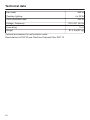
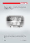
Operating and Installation Instructions Ventilation Hood To prevent accidents and damage to the appliance, you must read these instructions before installing the appliance and using it for the first time. en-US M.-Nr. 09 968 400 Contents IMPORTANT SAFETY INSTRUCTIONS................................................................. 3 Caring for the environment ................................................................................. 12 Description of functions ...................................................................................... 13 Guide to the appliance......................................................................................... 14 Operation .............................................................................................................. 16 Turning on the fan .................................................................................................. 16 Selecting the power level....................................................................................... 16 Turning off the fan .................................................................................................. 17 Turning cooktop lighting On/Off............................................................................. 17 Automatic safety shut-down.................................................................................. 17 Cleaning and care ................................................................................................ 18 Stainless steel housing .......................................................................................... 18 Grease filters .......................................................................................................... 19 OdorFree Charcoal Filter........................................................................................ 21 Disposing of the OdorFree Charcoal Filter........................................................ 21 Changing a halogen lamp ...................................................................................... 22 Installation ............................................................................................................ 23 Before installation .................................................................................................. 23 Installation parts..................................................................................................... 23 Appliance dimensions............................................................................................ 24 Distance between cooktop and ventilation hood (S) ............................................. 25 Installation recommendations................................................................................ 26 Structural support .................................................................................................. 26 Removing the protective film ................................................................................. 26 Exhaust duct......................................................................................................... 38 Condensate trap .................................................................................................... 39 Electrical connection ........................................................................................... 40 Grounding Instructions .......................................................................................... 40 Service and warranty ........................................................................................... 41 Location of the data plate ...................................................................................... 41 Technical data ..................................................................................................... 42 2 IMPORTANT SAFETY INSTRUCTIONS READ AND SAVE THESE INSTRUCTIONS This appliance complies with current safety requirements. Improper use of the appliance can lead to personal injury and material damage. Read all instructions before installing or using the appliance for the first time. Only use the appliance for its intended purpose. Keep these operating instructions in a safe place and pass them on to any future user. Use CAUTION: For General Ventilating Use Only. Do Not Use To Exhaust Hazardous Or Explosive Materials And Vapors. This appliance is intended for residential use only. Use only as described in these operating instructions. This ventilation hood is designed for domestic use and for use in similar residential environments. This ventilation hood is not intended for outdoor use. It must only be used to extract and clean vapors produced during cooking. Any other use occurs at the owner's own risk. This appliance is suitable for installation above gas or electric cooking surfaces. Persons who lack physical, sensory or mental abilities, or experience with the appliance should not use it without supervision or instruction by a responsible person. 3 IMPORTANT SAFETY INSTRUCTIONS Children As with any appliance, close supervision is necessary when used by children. Danger of suffocation! Ensure that any plastic wrappings, bags, etc. are disposed of safely and kept out of the reach of children. Technical safety WARNING: TO REDUCE THE RISK OF FIRE, ELECTRIC SHOCK, OR INJURY TO PERSONS, OBSERVE THE FOLLOWING: – Use this appliance only in the manner intended by the manufacturer. If you have questions, contact Miele. – Before servicing or cleaning the appliance, switch power off at the service panel and lock the service disconnecting means to prevent power from being switched on accidentally. If the service disconnecting means cannot be locked, securely fasten a prominent warning device, such as a tag, to the service panel. Installation, repair and maintenance work should be performed by a Miele authorized service technician in accordance with national and local safety regulations and the provided installation instructions. Contact Miele’s Technical Service Department for examination, repair or adjustment. Repairs and other work by unauthorized persons could be dangerous and may void the warranty. A damaged ventilation hood oven can be dangerous. Always check for visible signs of damage. Never use a damaged ventilation hood. Be certain your appliance is properly installed and grounded by a qualified technician. To guarantee the electrical safety of this appliance, continuity must exist between the appliance and an effective grounding system. It is imperative that this basic safety requirement be met. If there is any doubt, have the electrical system of the house checked by a qualified electrician. 4 IMPORTANT SAFETY INSTRUCTIONS To avoid damaging the ventilation hood, make sure that the connection data (voltage and frequency) on the data plate correspond to the building's power supply before connecting the appliance. When in doubt, consult a qualified electrician. Do not use a power bar or extension cord to connect the ventilation hood to electricity. These are a fire hazard and do not guarantee the required level of appliance safety. To ensure safe operation, only use the ventilation hood after it has been properly installed. This ventilation hood may not be used in non-stationary locations (e.g. on a ship). Only open the housing as described in the enclosed "Installation diagram" and in the "Cleaning and care" section of this manual. Under no circumstances should any other parts of the housing be opened. Tampering with electrical connections or components and mechanical parts is highly dangerous to the user and can cause operation faults. Defective components should be replaced by Miele original parts only. Only with these parts can the manufacturer guarantee the safety of the appliance. During installation, maintenance, and repair work, the ventilation hood must be disconnected from the electrical supply. It is only completely isolated from the electricity supply if one of the following applies: – The circuit breakers on the electrical service panel are tripped. – The screw-type fuses on the electrical service panel have been removed. – The power cable (if present) has been unplugged from the socket (pull the plug not the cord). 5 IMPORTANT SAFETY INSTRUCTIONS Proper use WARNING: TO REDUCE THE RISK OF A COOKTOP GREASE FIRE: – a) Never leave surface units unattended at high settings. Boilovers cause smoking and greasy spillovers may ignite. Heat oils slowly on low or medium settings. – b) Always turn the hood on when cooking at a high heat. – c) Clean the ventilation hood frequently. Grease should not be allowed to accumulate on the fan or filter. – d) Use the proper pan size. Always use cookware appropriate for the size of the cooking area. Never use an open flame beneath the ventilation hood. To avoid the risk of fire, do not flambé or grill over an open flame. When turned on, the ventilation hood will draw any flames into the filter. Fat deposits may ignite. 6 IMPORTANT SAFETY INSTRUCTIONS WARNING: TO REDUCE THE RISK OF INJURY TO PERSONS IN THE EVENT OF A COOKTOP GREASE FIRE, OBSERVE THE FOLLOWING*: – a) SMOTHER FLAMES with a close fitting lid, cookie sheet, or metal tray then turn off the burner. BE CAREFUL TO PREVENT BURNS. If the flames do not go out immediately, EVACUATE AND CALL THE FIRE DEPARTMENT. – b) NEVER PICK UP A FLAMING PAN - You may be burned. – c) DO NOT USE WATER, including wet dishcloths or towels - a violent steam explosion will result. – d) Use a fire extinguisher ONLY if: – 1) You have a class ABC extinguisher, and you know how to operate it. – 2) The fire is small and contained in the area where it started. – 3) The fire department is being called. – 4) You can fight the fire with your back to an exit. *Based on "Kitchen Firesafety Tips" published by NFPA. The ventilation hood may become damaged if exposed to excessive heat from a gas cooktop. – When using the ventilation hood over a gas cooktop, ensure that any burners in use are always covered by cookware. Turn burners off when removing the cookware, even if doing so for just a short time. – Select cookware that is suitable for the size of the burner. – Adjust the flame so that it never extends up the sides of the cookware. – Avoid overheating the cookware (e.g., when cooking with a wok). Always turn the ventilation hood on whenever a burner is in use to prevent damage from condensation. 7 IMPORTANT SAFETY INSTRUCTIONS Overheated oils and fats can ignite and set the ventilation hood on fire. When cooking with oils or fats, do not leave pots, pans or fryers unattended. Never leave an electric grill unattended when grilling. Fat and debris deposits impair the proper functioning of the ventilation hood. To ensure that cooking vapors are properly cleaned, never use the ventilation hood without the grease filters in place. A filter containing too much grease is a fire hazard! The filters should be cleaned or replaced at regular intervals. Please note that the heat rising from the stovetop during cooking can cause the ventilation hood to become very hot. Do not touch the housing or the grease filters until the ventilation hood has cooled down. 8 IMPORTANT SAFETY INSTRUCTIONS Proper installation WARNING: TO REDUCE THE RISK OF FIRE, ELECTRIC SHOCK, OR INJURY TO PERSONS, OBSERVE THE FOLLOWING: – a) Installation work and electrical wiring must be done by qualified person(s) in accordance with all applicable codes and standards, including fire-rated construction. – b) Sufficient air is needed for combustion and exhausting of gases through the flue (chimney of fuel burning equipment to prevent back drafting. Follow the heating equipment manufacturer’s guideline and safety standards such as those published by the National Fire Protection Association (NFPA) and the American Society for Heating, Refrigeration and Air Conditioning Engineers (ASHRAE), and the local code authorities. – c) When cutting or drilling into the wall or ceiling, do not damage electrical wiring and other hidden utilities. – d) Ducted hoods must always be vented to the outdoors. – e) Do not use this hood with any solid-state speed control device. To determine whether a ventilation hood may be operated above your cooking appliance, please refer to the information provided by the appliance's manufacturer. Safety regulations prohibit the installation of a ventilation hood above solid fuel stoves. Insufficient distance between the cooking appliance and the ventilation hood can result in damage to the hood. The minimum safety distances between the appliance and the bottom of the ventilation hood specified in the "Installation" section must be maintained, unless the appliance's manufacturer has indicated that a greater distance is required. If more than one cooking appliance is used beneath the ventilation hood, and if different minimum safety distances apply for these appliances, you should use the greater distance. 9 IMPORTANT SAFETY INSTRUCTIONS Be sure to observe the information contained in the "Installation" section when mounting the ventilation hood. Metal parts can have sharp edges which may cause injury. Wear gloves to protect your hands from being cut. When installing the exhaust duct, only use pipes or tubes made of non-flammable material. These can be obtained from your Miele dealer or from Miele Technical Service. Exhaust air should not be vented into a chimney or vent flue which is otherwise in use and should not be channeled into ducting which ventilates rooms with fuel-burning installations. If exhaust air is to be extracted into a chimney or vent flue no longer used for other purposes, be sure to comply with all applicable regulations. WARNING: TO REDUCE THE RISK OF FIRE USE ONLY METAL DUCTWORK. 10 IMPORTANT SAFETY INSTRUCTIONS Cleaning and care Never use a steam cleaner to clean the ventilation hood. The steam can reach the electrical components and cause a short circuit. Accessories Use only genuine original Miele parts. If parts or accessories from other manufacturers are used, the warranty will become void. 11 Caring for the environment Disposal of the packing material The cardboard box and packing materials protect the appliance during shipping. They have been designed to be biodegradable and recyclable. Ensure that any plastic wrappings, bags, etc. are disposed of safely and kept out of the reach of children. Danger of suffocation! 12 Disposal of your old appliance Do not dispose of this appliance with your household waste. Old appliances may contain materials that can be recycled. Please contact your local recycling authority about the possibility of recycling these materials. Before discarding an old appliance ensure that it presents no danger to children while being stored for disposal. Unplug it from the outlet, cut off its power cord and remove any doors to prevent hazards. Description of functions The following functions are available on your ventilation hood, depending on the model: Vented mode The air is drawn in and cleaned by the grease filters and directed outside. Non-return flap A non-return flap in the ducting prevents the exchange of inside and outside air from occurring when the ventilation hood is not in use. The flap is closed when the ventilation hood is turned off. When the ventilation hood is turned on, the non-return flap opens so that the exhaust air can be transported outside without any obstruction. Recirculation mode The recirculation mode requires a recirculation kit and OdorFree Charcoal Filter (available as optional accessories, see "Technical Data" for more information) The air is drawn in and first cleaned by the grease filters and then by an OdorFree Charcoal Filter. The cleaned air is then recirculated back into the kitchen. A non-return flap has been provided with the hood in case your ducting does not have one. It is inserted into the outlet duct collar of the fan. 13 Guide to the appliance 14 Guide to the appliance a Telescopic chimney b Chimney c Canopy d Control panel e Grease filter f Spacer frame The spacer frame creates a shadow gap between the chimney and the ceiling. The ventilation hood can be installed with or without the spacer frame. g Recirculation vent (only for recirculation mode) h Cooktop lighting i OdorFree Charcoal Filter Optional accessory for recirculation mode j On/Off button for fan k Buttons for setting the fan power l Button for cooktop lighting 15 Operation Press the On/Off button . Automatically switching back from the intensive level (IS) The fan turns on at level 2. The symbol and 2 will light up in the fan level display. The intensive level can be programmed to switch back to level 3 automatically after 10 minutes. Selecting the power level To do so, turn off the fan and the cooktop lighting. Turning on the fan Power levels 1 to 3 can be used for light to heavy cooking vapors and odors. For strong vapors and odors that are temporarily produced when cooking, e.g. during searing, select the IS level as an intensive setting. Press the "" button for a lower power level or the "" button to select a higher level. Press the and buttons at the same time for approx. 10 seconds, until 1 lights up. Then, press the following buttons in order: – The lighting button , – Followed by the button and then – The lighting button again. If automatic switch-off is not activated, the 1 and IS displays will flash. To activate it, press the button. If 1 and IS are lit up, automatic switchoff is activated. To deactivate it, press the button. Use the On/Off control to confirm your choice of setting. If you do not confirm within 4 minutes, the hood will revert to the old setting. 16 Operation Turning off the fan Press the On/Off button to turn the fan off. The symbol will go out. Turning cooktop lighting On/Off The cooktop lighting can be turned on and off separately from the fan. To do so, press the button. The symbol is lit when the cooktop lighting is turned on. Automatic safety shut-down Should the hood be left on, the fan will switch off automatically after 10 hours. The lighting will remain on. Pressing the On/Off button will switch the fan back on again. 17 Cleaning and care WARNING: TO REDUCE THE RISK OF FIRE, ELECTRIC SHOCK, OR INJURY TO PERSONS, OBSERVE THE FOLLOWING: Before cleaning or servicing the hood, disconnect it from the power supply, see "IMPORTANT SAFETY INSTRUCTIONS". Stainless steel housing General The surfaces and control buttons are susceptible to scratching and chipping. Observe the following cleaning instructions. Clean all surfaces and control buttons using warm water and liquid dish soap only, applying the mixture with a sponge cloth. Make sure that no water gets into the interior of the hood. Only use a damp cloth to clean the hood, especially in the control panel area. After cleaning, dry the surfaces with a soft cloth. Avoid the following: – Cleaners containing soda, acid or chloride, or cleaners containing solvents – Abrasive cleaners such as scouring powder, scouring liquid, abrasive sponges such as pot scourers, or used sponges that still contain residues from abrasive cleaners 18 Special instructions for stainless steel surfaces (does not apply to control buttons) Stainless steel surfaces can also be cleaned using a non-abrasive stainless steel cleaner, available from Miele. To prevent the surfaces from quickly becoming dirty again, we recommend treating them with a stainless steel care conditioner. Apply sparingly over the entire area using a soft cloth. Special instructions for RAL color finish housing (special order) Observe the general cleaning instructions contained in this chapter. Minor scratches on the surface are inevitable when cleaning the housing. Depending on the lighting in the kitchen, this may negatively affect the appliance's appearance. Cleaning and care Special instructions for control buttons Do not leave dirt and debris on the buttons for any length of time. Otherwise they may become discolored or damaged. Remove any dirt or debris immediately. Observe the general cleaning instructions contained in this chapter. Do not use a stainless steel cleaner to clean the control buttons. Grease filters The reusable metal grease filters in the appliance remove the solid particles contained in kitchen vapors (fat, dust, etc.), thereby preventing the ventilation hood from becoming dirty. A dirty filter is a fire hazard! Cleaning intervals Over longer periods of time, fat buildup on the grease filter hardens and makes cleaning more difficult. Therefore, we recommend cleaning the grease filters once every 3-4 weeks. Removing the grease filters When handling a grease filter, be careful not to drop it. This can result in damage to the filter and to the cooktop. Make sure you hold the filter securely at all times when handling it. To remove a grease filter, release the locking clip. Then, open the filter to a 45° angle, unhook it, and remove it from the hood. 19 Cleaning and care Cleaning the grease filters by hand Clean the filters with a soft nylon brush in a mild solution of hot water and dish soap. Do not use undiluted dish soap. Unsuitable cleaning agents Unsuitable cleaners can cause damage to the filter surfaces if used regularly. Do not use any of the following: When removing the filters for cleaning, also clean off any accessible oil or fat buildup from the housing. Doing so will prevent a fire hazard. Reinstall the grease filters. When inserting the filters, make sure that the locking clip is facing down. – Lime removers – Abrasive powders or abrasive liquids – Aggressive all-purpose cleaners and degreaser sprays – Oven sprays Cleaning the grease filters in the dishwasher Place the filters as upright or inclined as possible in the lower basket. Ensure that the spray arm is not obstructed. Use a common household dishwasher detergent. Select a program with a wash temperature between 122°F (50°C) and 149°F (65°C). In a Miele dishwasher use the "Normal" program. Depending on the detergent used, cleaning the filters in a dishwasher may cause the inside filter surfaces to become discolored. However, this will not affect the functioning of the filters in any way. After cleaning After cleaning, leave the filters on an absorbent surface to dry. 20 If the filters have been installed incorrectly, you can insert a small screwdriver into the slit to disengage the locking clip. Cleaning and care OdorFree Charcoal Filter If the hood is equipped for recirculation, an OdorFree Charcoal Filter must be installed in addition to the grease filters. This filter is designed to absorb odorcausing agents and is mounted in the canopy above the grease filters. OdorFree Charcoal Filters are available from your Miele dealer or from Miele. See "Technical data" for the type and reference number. Installing/replacing the OdorFree Charcoal Filter When to change the OdorFree Charcoal Filter Always replace the OdorFree Charcoal Filter whenever it no longer absorbs kitchen odors effectively. Replace the filter at least once every 6 months. Disposing of the OdorFree Charcoal Filter Used OdorFree Charcoal Filters can be disposed of with normal household waste. To install or replace the OdorFree Charcoal Filter, the grease filters must first be removed as described above. Remove the OdorFree Charcoal Filter from its packaging. Press the OdorFree Charcoal Filter into the frame. Reinstall the grease filters. 21 Cleaning and care Changing a halogen lamp The halogen lights become very hot during operation. They can cause burns even after being shut off for some time. Allow them to cool down for a few minutes before changing the halogen lamps. Disconnect the ventilation hood from the electrical supply before replacing the lamps (see "IMPORTANT SAFETY INSTRUCTIONS"). To access the halogen lamp, press the lamp cover gently upwards. The cover will open and can then be lowered. Pull the halogen lamp out of its socket. Replace it with a new halogen lamp (12 V, 20 W, G4). Wear a glove or use a soft cloth to hold it and push it into the socket carefully. Please follow the lamp manufacturer's instructions. Flip the cover back up, making sure it clicks into place. 22 Installation Before installation Before installing the appliance, read all of the information contained in this chapter and also in the "IMPORTANT SAFETY INSTRUCTIONS" section. 4 extension piece holders for aligning and securing the telescopic chimney Installation parts 4 screws, 6 9/16" x 4 5/16" (7 x 110 mm) and 4 plugs, 3/8" x 3 1/8" (10 x 80 mm) for securing the ventilation hood to the ceiling (not for use in USA / CDN). The screws and plugs are designed for use in solid ceilings only. Use different fasteners for other ceiling construction types. Make sure that the ceiling can support the load. 4 screws M3/16" x 5/16" (M4 x 8.5 mm) for securing the extension piece holders. 14 screws M3/16" x 5/16" (M4 x 8 mm) for securing the spacer frame and securing the hood to the installation frame. 1 screw M3/16" x 5/8" (M4 x 16 mm) for securing the chimney. DUI 32 recirculation kit for recirculation mode (not supplied, available as an optional accessory). The kit includes a directional unit, aluminum hose, and hose clips. 23 Installation Appliance dimensions a Mounting area for the exhaust ducting and power cable. In recirculation mode, only the power cord is required. b Possible height range for appliance in vented mode c Possible height range for appliance in recirculation mode d Alternative installation with spacer frame e Air vent positioned at the top for recirculation 24 Installation f A power cord is required to connect the hood to the socket in the ceiling. With extraction mode flexible ducting is also required. Exhaust connection 6" (150 mm) Distance between cooktop and ventilation hood (S) Provided a larger distance is not given by the manufacturer of the cooktop, follow the minimum safety distances between a cooktop and the bottom of the hood. Please also observe the information contained in the "IMPORTANT SAFETY INSTRUCTIONS" section. Minimum distance S Cooking appliance Miele appliance Non-Miele appliance Electric/Induction cooktop 24" (610 mm) Electric grill, deep fat fryer (electric) 26" (660 mm) Multi-burner gas cooktop ≤ 43,000 BTU/hr (12.6 W), no burner > 15,000 BTU/hr (4.5 kW). 26" (660 mm) 30" (760 mm) Multi-burner gas cooktop ≤ 73,800 BTU/hr (21.6 W), no burner > 16,500 BTU/hr (4.8 kW) 30" (760 mm) Multi-burner gas cooktop > 73,800 BTU/hr (21.6 W), or one of the burners > 16,500 BTU/hr (4.8 kW) Not possible Single-burner gas cooktop ≤ 20,500 BTU/hr (6 kW) 26" (660 mm) 30" (760 mm) Single-burner gas cooktop ≤ 27,600 BTU/hr (8.1 kW) 30" (760 mm) Single-burner gas cooktop > 27,600 BTU/hr (8.1 kW) Not possible 25 Installation Installation recommendations Structural support – We also recommend a distance of at least 25 1/2" (650 mm) above electric cooktops to provide more workspace and easier cooking under the hood. – When selecting an installation height, always take the user height into consideration. Users should have ample space to work comfortably on the cooktop and reach the ventilation hood controls with ease. – Please note that the greater the distance from the cooktop, the less effective the hood is at drawing in the cooking vapors. – To achieve optimal vapor extraction, make sure that the hood covers the cooktop. The hood should be positioned centrally over the cooktop, not to the side or rear. – The cooktop should be no wider than the hood. Preferably, it should be narrower. – The mounting area must be easily accessible. The ventilation hood should be easy to reach and disassemble in case a service call is necessary. This should be taken into consideration when planning the position of cupboards, shelves, ceilings or decorative elements in the vicinity of the ventilation hood. 26 The hood must be attached to rigid structural framing that is supported in its entirety by the ceiling joists, or to the ceiling joists directly. Do not attach the plate directly to the ceiling with anchors, toggle bolts, etc. Removing the protective film The housing components are covered by a protective film to prevent them from becoming damaged during transport. Please remove this film before installing the housing components. It can be peeled off easily without any additional tools. Installation 8 2 5/8 5/8" 8 mm 20 m " 0 m 22 For vented mode: dai3435aus Draw two intersecting lines on the ceiling. – Place a section of the exhaust ducting in the ceiling and feed it down through the cross-sectional area as illustrated. Exhaust ducting of approx. 27 9/16" (700 mm) length is required between the ceiling and the hood exhaust socket. – Secure the exhaust ducting to the exhaust socket, e.g. with a hose clip (available as an optional accessory) on flexible ducting. Place the power cord and guide it through the ceiling in the area shown. A power cord approx. 27 9/16" (700 mm) in length is required between the ceiling and the hood connectors. 27 Installation Use a knife to release the four spacers and the two covers from the spacer frame supplied. Drill four holes 3/8" (10 mm), approx. 4 1/2" (115 mm) deep for the plugs supplied. Use the spacer frame as a drilling template. Place it on the ceiling with the arrows pointing forwards. Using the notches, align the spacer frame on the intersecting lines and make pencil marks for the drill holes. 28 Place the four plugs in the holes and screw in the four screws so that they protrude by approx. 1 3/16" (30 mm). Installation The spacer frame can be installed between the chimney and the ceiling. This creates a shadow which gives the illusion of a gap between the ceiling and the chimney. This is useful if the ceiling is not level or is uneven. The hood is aligned vertically with the spacers supplied. Visual irregularities between the chimney and the ceiling are then concealed by the shadow. Mount the spacer frame onto the installation frame. If you wish to install the hood with the spacer frame, remove the four inserts from the fixing holes. 29 Installation Hang the installation frame on the four screws. The front of the frame is marked with a "V." If using the spacer frame, place the two covers into the fixing holes. 30 Align the installation frame and secure it with the screws. The spacers, which were removed from the spacer frame at the start, can be used to align the hood vertically. Installation Holding the installation frame securely, remove the two fixing screws and extend the installation frame to its maximum length. Replace the screws. The directional unit from recirculation kit DUI 32 (optional accessory) is installed for recirculation mode (RM): Bend the four retaining tabs on the installation frame outwards. Place the power cord inside the installation frame. Fit the directional unit as shown, noting the marking on the front. Bend the retaining tabs back and approx. 45° inwards to hold the directional unit in place. 31 Installation Secure the exhaust socket to the hose using a hose clip. Secure the hose to the directional unit socket using a hose clip. Check that the hose is held securely. Push the telescopic chimney over the installation frame: – with the recirculation grilles at the bottom for vented mode (AE), – with the recirculation grilles at the top for recirculation mode (RM). Bend the two retaining tabs outwards to prevent the telescopic chimney from slipping down again. 32 Installation Fit the four telescopic chimney clamps. When the screws are tightened, the clamps spread out and push the telescopic expansion piece upwards. Bend back the two retaining tabs. Push the chimney over the telescopic chimney and bend the retaining tabs outwards again to prevent the chimney from slipping down again. Tighten the screws only until the top edge of the telescopic chimney is evenly aligned with the ceiling or the spacer frame. 33 Installation A non-return flap is supplied with the hood or is already fitted in the exhaust socket of the motor unit (depending on model). With vented mode (AE) insert the non-return flap in the exhaust socket if your ducting system is not equipped with one. Recirculation mode (RM) does not require the non-return flap to be inserted. If there is one present, it should be removed. Hang the ventilation hood canopy on the chimney by pushing the canopy up into the installation frame and pressing the retaining clips into the openings as shown. Ensure the controls are at the front. Secure the hood with the screws supplied. 34 Installation Connect the power cord. See "Electrical connection." Unscrew both screws from the installation frame again. Place the exhaust ducting onto the exhaust socket. The canopy can now be adjusted to the desired height, observing the permissible height ranges: – With vented mode: upwards as far as it will go, downwards only to the "A" marking. – With recirculation mode: upwards as far as the "U", downwards as far as it will go. Follow the instructions in "Appliance dimensions." Safety distances between the cooktop and ventilation hood must be observed. 35 Installation Raise the canopy to the desired height and secure it with the screws. Hold the chimney securely, bend back the retaining tabs and carefully lower it. The chimney will locate in the cut-out in the canopy. 36 Installation With recirculation mode (RM) ventilation hoods, insert the OdorFree Charcoal Filter. Remove the grease filters from the hood. Insert the safety screw on the inside. Carefully remove the protective foil from the grease filters. Reinsert the grease filters. 37 Exhaust duct WARNING: Danger of toxic fumes. Gas cooking appliances release carbon monoxide that can be harmful or fatal if inhaled. To reduce the risk of fire and to properly exhaust air, the exhaust gases extracted by the hood should be vented outside of the building only. Do not vent exhaust air into spaces within walls or ceilings or in attics, crawl spaces or garages. To reduce the risk of fire, only use metal ductwork. Please read and follow the "IMPORTANT SAFETY INSTRUCTIONS" to reduce the risk of personal injury. Follow all local building codes when installing the hood. Only use smooth pipes or flexible duct hoses made from nonflammable materials for exhaust ductwork. To achieve the greatest possible air extraction with the lowest noise levels, please note the following: – The diameter of the exhaust duct should not be less than 6" (150 mm). – If flat exhaust ducts are used, the cross section should not be smaller than that of the exhaust connector. – The exhaust duct should be as short and straight as possible. – If elbows are needed, make sure they have a large radius. – The exhaust duct itself must not be kinked or compressed. 38 – Make sure that all connections are secure and airtight. Remember that any constriction of the airflow will reduce extraction performance and increase operating noise. If the exhaust duct is to be routed through an outside wall, we recommend installing a telescopic wall vent or a rooftop vent (available as an optional accessory). If the exhaust air is to be conducted into a vent flue, the intake piece must be aligned with the flow direction of the flue. When installing the exhaust duct horizontally, you must slope it away from the source by at least 1 cm per meter (3/8" per 3 1/4'). This ensures that condensate cannot drain back into the ventilation hood. If the exhaust duct is to be routed through rooms, ceiling space etc., the temperatures in these different areas may differ greatly, which means that the problem of condensation will need to be addressed. The exhaust duct will need to be insulated. Exhaust duct Condensate trap In addition to insulating the exhaust duct, we recommend installing a condensate trap to collect and evaporate any condensate which might accumulate. Condensate traps are available for exhaust ducts with a diameter of 5" (125 mm) or 6" (150 mm). When installing a condensate trap, make sure that it is positioned vertically and, if possible, directly above the hood outlet duct collar. The arrow on the housing indicates the direction of airflow. 39 Electrical connection WARNING: TO REDUCE THE RISK OF FIRE, ELECTRIC SHOCK, OR INJURY TO PERSONS, OBSERVE THE FOLLOWING: All electrical work should be performed by a qualified electrician in strict accordance with national regulations (for USA: ANSI-NFPA 70) and local safety regulations. Installation, repairs and other work by unqualified persons could be dangerous. Ensure that power to the appliance is OFF while installation or repair work is performed. Verify that the voltage, load and circuit rating information found on the data plate (located behind the baffle filters), match the household electrical supply before installing the hood. Use only with ventilation hood cordconnection kits that have been investigated and found acceptable for use with this model hood. If there is any question concerning the electrical connection of this appliance to your power supply, please consult a licensed electrician or call Miele’s Technical Service Department. WARNING: THIS APPLIANCE MUST BE GROUNDED 40 Grounding Instructions WARNING - Improper grounding can result in a risk of electric shock. This appliance must be grounded. In the event of an electrical short circuit, grounding reduces the risk of electric shock by providing a path of least resistance.plug. If there is any doubt, have the electrical system of the house checked by a qualified electrician. To increase security before the machine is installed, it is recommended to install a protective switch(30mA). The hood must be hard wired accordingly: Black/Red wire: connect to L1 (live) White wire: connect to N (neutral) Green wire: connect to GND (ground) Service and warranty For faults that you cannot resolve on your own, please contact your Miele dealer or Miele Technical Service. The telephone number for the Technical Service Department is listed at the back of these instructions. When contacting Miele, please state the model and serial number of your ventilation hood. These can be found on the data plate. Location of the data plate The data plate is visible once you have removed the grease filters. Warranty For further information, please refer to your warranty booklet. 41 Technical data Fan motor Cooktop lighting Total connected load Voltage, Frequency Fuse rating Weight Optional accessories for recirculation mode: Recirculation kit DUI 32 and OdorFree Charcoal Filter DKF 12 42 350 W 4 x 20 W 430 W 120 V AC, 60 Hz 15 A 81.4 lbs (37 kg) Please have the model and serial number of your appliance available before contacting Technical Service. U.S.A. Canada Miele, Inc. Importer Miele Limited National Headquarters 9 Independence Way Princeton, NJ 08540 Phone: 800-843-7231 609-419-9898 609-419-4298 Fax: www.mieleusa.com Technical Service & Support Nationwide Phone: 800-999-1360 888-586-8056 Fax: [email protected] Headquarters and Miele Centre 161 Four Valley Drive Vaughan, ON L4K 4V8 www.miele.ca Customer Care Centre Phone: 800-565-6435 905-532-2272 [email protected] Germany Manufacturer Miele & Cie. KG Carl-Miele-Straße 29 33332 Gütersloh 43 DA 390-6 en-US M.-Nr. 09 968 400 / 00