1
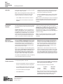
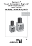
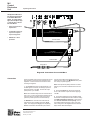
M-5
Control
Electronics
Unit
The Meyer Sound M-5 is an active signal processor designed
for use with the MSL-5 loudspeaker. It is a single channel
device, and it occupies a single
13⁄4-inch rack space. The functions of the M-5 are:
Operating Instructions
PUSH
+
+
+
-
-
-
-
GND
Input
1
Input
Active crossover for biamplification.
90-250 VAC
50-60 Hz
100mA MAX
90-105
105-125
AC Voltage Ranges
Lo Sense
Hi Sense
2
Lo Out
Hi Out
210 - 250
180 - 210
105 - 125
90 - 105
210-250
180-210
AC Voltage
1/4 A SloBlo
4
3
(Red)
•
CAUTION: Set voltage before applying power.
+
Lift
(Black)
PUSH
•
Loudspeaker frequency
response and phase
response alignment.
Hi Amplifier:
Type 3 Amplifier with 16 dB fixed voltage gain.
Hi Input
Hi Output
–
•
MultiSense™ driver
protection.
+
Hi Sense Cable
PUSH
Lo Amplifier:
Type 3 Amplifier with 16 dB fixed voltage gain.
Lo Input
Lo Output
–
+
Lo Sense Cable
Out to MSL-5
Diagram A: Connections for use with MSL-5
Connections
The M-5 operates at line level and is designed to be the
last component in the signal chain before the power
amplifiers. Connections to the M-5 should be made
according to Diagram A.
1. Signal Inputs to the M-5 should be balanced. For
the best signal-to-noise ratio, the average input level
should be at least 1 volt RMS. The M-5 will accept
peak inputs of up to +26 dBV.
Note: The M-5 utilizes Meyer Sound’s exclusive ISO™
Input. Pins 1, 2 and 3 are transformer-isolated, and the
connector shell is connected to earth ground (pin 3
positive for positive pressure out from the MSL-5).
2. MultiSense™ connections are made from the
outputs of the power amplifiers to the M-5 Sense
inputs. The output(s) of the High power amplifier(s)
must be connected to the Hi Sense inputs, and the
Meyer Sound Laboratories, Inc.
2832 San Pablo Avenue
Berkeley, CA 94702
output(s) of the Low power amplifier(s) to the Lo
Sense inputs in order for the MultiSense driver protection circuitry to operate properly.
Note: These inputs are polarity-sensitive: be certain
that they are connected as indicated on the M-5 rear
panel.
3. The signal Outputs from the M-5 are active balanced. The maximum output level before clipping is
+26 dBV.
4. Connections between the power amplifier outputs
and the MSL-5 loudspeaker should be made according
to the MSL-5 Operating Instructions. These connections must be verified for correct polarity, and correct amplifier assignments (high to high, low to low).
Color codes given in the diagrams are those used for
Meyer Sound cables and adapters.
M-5
Control
Electronics
Unit
Operation
Operating Instructions
Once all the connections have been made and verified,
the system is ready to operate.
Note: Check the voltage selector switch located on the
rear panel of the M-5 and verify that it is set to the
range that corresponds to the mains AC voltage.
Front Panel
Controls
•
The M-5 Attn control should be set at minimum.
•
Switch on AC to the M-5 first, then to the power
amplifiers.
The setup controls on the M-5 front panel are designed
to be used to tailor the system response for particular
applications.
Safe/Autosafe Switch. The M-5 incorporates three
limiters in the MultiSense™ driver protection circuitry
(see detailed description below). When the switch is in
the Safe position, the RMS limiters come on at 6 dB
lower power levels, affording added protection when
heavy continuous power demands are placed on the
system. For operator convenience, a green LED
MultiSense™
Driver Protection
•
Verify that the power amplifier voltage gains are fixed at
+16 dB (6.3 volts out for 1 volt in, measured from balanced input to speaker output terminals).
•
Advance the M-5 Attn control to set the system sensitivity. If the system is not operating properly, recheck all
connections.
Note: The Attn control markings are merely a visual aid and
should not be used to balance two systems. The output of
the M-5 is calibrated only when the level control is fully
clockwise.
indicator is provided on the M-5 front panel which lights
when the M-5 is in the Safe mode. When the switch is in the
Autosafe position, the M-5 monitors system power over
time and automatically switches into Safe mode if the power
demands become too high. In the case that Autosafe
switches the M-5 into Safe mode, the green LED will light to
indicate the change.
Note: It is recommended that the switch be in the Safe
position until the operator is familiar with the system’s
capablities.
Through the Sense connections between the M-5 and
the power amplifiers, the MultiSense circuitry of the M5 continuously monitors the voltages across the high
and low frequency drivers. If the amplifier output
exceeds the safe operating limits of the drivers, independent limiters are automatically activated, holding
down the level of the M-5 output.
•
Sense indicators. These function as signal presence
indicators and verify that the Sense connections back to
the M-5 are made. These indicators will be lit green
whenever signal is present, or will flicker at low signal
levels. These indicators will also light red if there is a
sense fault (amplifier gain not set at +16 dB or sense
lines improperly or not connected).
Note: The M-5 employs an excursion limiting system
which assumes a fixed amplifier voltage gain of +16
dB (6.3 volts out for 1 volt in). Please refer to the
MSL-5 Operating Instructions or the Meyer Sound
MSL-10A Power Amplifier Criteria note for a detailed
description of MSL-5 / M-5 amplifier requirements.
•
Limit indicators. These indicators will come on whenever the corresponding limiter is activated, and a moderate amount of flashing of these indicators is acceptable.
The Hi and Lo limiters have an attack time of 100 msec.,
so they will not affect peaks in the program material, nor
will they prevent momentary amplifier clipping on peaks.
•
Supply an input to the M-5, preferably a sine wave oscillator. If you do not have an oscillator, use a microphone
and a mixer to produce a line level signal.
•
Set the input frequency according to this table:
The operation of the MultiSense circuitry is indicated by
a set of five LEDs located on the front panel.
Limiter Operation
To verify limiter operation in the field:
•
•
Disconnect loudspeakers, leaving the amplifier and
the M-5 in their standard connection configuration.
If your amplifier requires a load, use resistive loads
sufficient to dissipate the full power of the amplifier.
•
Turn on both the M-5 and the amplifier.
•
Set the Safe switch in.
Meyer Sound Laboratories, Inc.
2832 San Pablo Avenue
Berkeley, CA 94702
Lo limiter
Hi limiter
•
Oscillator
200 Hz
5,000 Hz
Microphone
low growl
loud whistle
Bring up the input until you see the corresponding limit
indicator come on. Since in each case the indicator will
light only if the limiter actually operates, it provides a
positive indication that the limiter is functioning.
M-5
Control
Electronics
Unit
Operating Instructions
Meyer Sound Laboratories, Inc.
2832 San Pablo Avenue
Berkeley, CA 94702
M-5
Control
Electronics
Unit
Operating Instructions
Specifications
Input Type
Balanced ISO™ Input, 10 kΩ
Output Type
Active push-pull, will drive 600 Ω
Maximum Input/Output Level (Balanced)
+26 dBV
Hum and Noise
-90 dBV (“A” weighted)
Dynamic range
>110 dB
Sense Inputs
10 kΩ true differential
Electronic Crossover Frequency
900 Hz
Driver Protection Circuitry
Low Frequency
High Frequency
Indicators
Sense: Hi and Lo
Limit: Hi, Lo and VHF
Safe
Power Supply, Positive and Negative
Front Panel Controls
Connectors
Inputs/Outputs (Balanced)
Sense Inputs
RMS limiter (100 msec. integration time),
peak and excursion limiters
RMS limiter (100 msec. integration time),
peak and excursion limiters
Bi-color LEDs
Red LEDs
Green LED
Green LEDs
Level control, AC on/off,
Safe/AutoSafe switch
XLR-type (A-3)
Banana jacks
Power
90-100V / 105-120V / 180-200V / 210-240V AC
rear switchable
Physical Dimensions
19" W x 1 3⁄4" H x 7 3⁄4 “ D
Weight
8 lbs. (3.6 kg)
05.025.002.01 A
Meyer Sound Laboratories, Inc.
2832 San Pablo Avenue
Berkeley, CA 94702