1
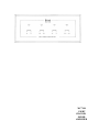
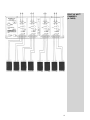
MC7108
EIGHT
CHANNEL
POWER
AMPLIFIER
MC7108
EIGHT
CHANNEL
POWER
AMPLIFIER
IMPORTANT
SAFETY
INSTRUCTIONS
THESE
INSTRUCTIONS
ARE TO PROTECT
YOU AND THE
MclNTOSH
INSTRUMENT.
BE SURE TO
FAMILIARIZE
YOURSELF
WITH THEM
1.
2.
3.
4.
5.
6.
7.
8.
9.
10.
11.
12.
13.
14.
15.
16.
Read all instructions - Read the safety and operating instructions before operating the instrument.
Retain Instructions - Retain the safety and operating instructions for future reference.
Heed warnings - Adhere to warnings and operating instructions.
Follow Instructions - Follow all operating and use instructions.
WARNING: TO REDUCE RISK OF FIRE OR ELECTRICAL SHOCK, DO NOT EXPOSE THIS INSTRUMENT TO RAIN OR MOISTURE.
Power Sources - Connect the power supply only to the type described in the operating instructions
or as marked on the unit.
Power-Cord Protection - Route power-supply cords so that they are not likely to be walked on or
pinched by items placed upon or against them, paying particular attention to cords at plugs,
convenience receptacles, and the point where they exit from the instrument.
Ventilation - Locate the instrument for proper ventilation. For example, the instrument should not
be placed on a bed, sofa, rug, or similar surface that may block ventilation openings; or, placed
in a built-in installation, such as a bookcase or cabinet, that may impede the flow of air through
the ventilation openings.
Heat - Locate the instrument away from heat sources such as radiators, heat registers, stoves, or
other appliance (including amplifiers) that produce heat.
Wall or Cabinet Mounting - Mount the instrument in a wall or cabinet only as described in the owner's
manual.
Water and Moisture - Do not use the instrument near water - for example, near a bathtub, washbowl,
kitchen sink, laundry tub, in a wet basement, or near a swimming pool, etc.
Cleaning - Clean the instrument by dusting with a dry cloth. Clean the panel with a cloth moistened
with a window cleaner.
Object and Liquid Entry - Do not permit objects to fall and liquids to spill into the instrument through
enclosure openings.
Nonuse Periods -Unplug the power cord from the AC power outlet when left unused for a long period
of time.
Damage Requiring Service - Service must be performed by qualified service personnel when:
A. The power supply cord or the plug has been damaged; or
B. Objects have fallen, or liquid has been spilled into the instrument; or
C. The instrument has been exposed to rain; or
D. The instrument does not appear to operate normally or exhibits a marked change in performance;
or
E. The instrument has been dropped, or the enclosure damaged.
Servicing - Do not attempt to service beyond that described in the operating instructions. All other
service should be referred to qualified service personnel.
Grounding or Polarization - Do not defeat the inherent design features of the polarized plug. Nonpolarized line cord adaptors will defeat the safety provided by the polarized AC plug.
17. CAUTION: TO PREVENT ELECTRICAL SHOCK DO NOT USE THIS (POLARIZED) PLUG
WITH AN EXTENSION CORD, RECEPTACLE OR OTHER OUTLET UNLESS THE BLADES CAN
BE FULLY INSERTED TO PREVENT BLADE EXPOSURE.
ATTENTION: POUR PREVENIR LES CHOCS ELECTRIQUES PAS UTILISER CETTE
FICHE POLARISEE AVEC UN PROLONGATEUR, UNE PRISE DE COURANT OU UNE AUTRE
SORTIE DE COURANT, SAUF Sf LES LAMES PEUVENT ETRE INSEREES A FOND SANS EN
LAISSER AUCUNE PARTIE A DECOUVERT.
The lightning flash with arrowhead, within an equilateral triangle, is intended to alert the
user to the presence of uninsulated "dangerous voltage" within the product's enclosure
that may be of sufficient magnitude to constitute a risk of electric shock to persons.
CAUTION: TO PREVENT THE RISK OF ELECTRIC SHOCK, DO NOT
REMOVE COVER (OR BACK). NO USER-SERVICABLE PARTS INSIDE.
REFER SERVICING TO QUALIFIED PERSONNEL.
The exclamation point within an equilateral triangle is intended to alert the user to the
presence of important operating and maintenance (servicing) instructions in the literature
accompanying the appliance.
Copyright 1993 © by
Mclntosh Laboratory Inc.
WARNING: THIS UNIT IS CAPABLE OF PRODUCING HIGH SOUND
PRESSURE LEVELS. CONTINUED EXPOSURE TO HIGH SOUND
PRESSURE LEVELS CAN CAUSE PERMANENT HEARING IMPAIRMENT
OR LOSS. USER CAUTION IS ADVISED AND EAR PROTECTION IS
RECOMMENDED WHEN PLAYING AT HIGH VOLUMES.
2
Your decision to own this piece of Mclntosh Stereo Equipment ranks you at the very top
among discriminating music listeners. You now have "The Best". The Mclntosh dedication
to ''Quality", is assurance that you will receive thousands of hours of musical enjoyment from
this unit.
THANK
YOU
Please take a short time to read the information in this manual. We want you to be as familiar
as possible with all the features and functions of your new piece of Mclntosh. This will ensure that you receive all the performance benefits this instrument can offer you, and that
it will become a highly valued part of your home music system.
The serial number, purchase date, and Mclntosh Laboratory Service Contract number are
important to you for possible insurance claim or future service. Record this information here-
Serial Number
Purchase Date
Service Contract Number
Upon application, Mclntosh Laboratory provides a Service Contract to the original purchaser.
Your Mclntosh Authorized Service Agency can expedite repairs when you provide the Service Contract with the instrument for repair.
SERVICE CONTRACT
4
INTRODUCTION
5
HOW TO INSTALL THE MC7108
5
FRONT PANEL DISPLAYS
6
REAR PANEL AND HOW TO MAKE CONNECTIONS
CUSTOM INSTALLATION DIAGRAMS
SPEAKER-AMPLIFIER CONNECTION DIAGRAMS
SPECIFICATIONS
6, 7, 8, 9, 10
10
11, 12, 13, 14, 15, 16, 17
18
3
TABLE OF
CONTENTS
TAKE ADVANTAGE OF 3 YEARS OF CONTRACT SERVICE
FILL IN THE APPLICATION NOW.
Your MC7108 Eight Channel Power Amplifier will give you many years of satisfactory performance. If you have any questions, please contact,
Mclntosh Laboratory Inc.
2 Chambers Street
Binghamton, New York 13903-2699
Phone: 607-723-3512
McINTOSH
THREE YEAR
SERVICE
CONTRACT
An application for A THREE YEAR SERVICE CONTRACT is included with this manual.
The terms of the contract are:
1. If the instrument covered by this contract becomes defective, Mclntosh will provide all parts,
materials, and labor needed to return the measured performance of the instrument to the
original performance limits free of any charge. The service contract does not cover any
shipping costs to and from the authorized service agency or the factory.
2. Any Mclntosh authorized service agency will repair ail Mclntosh instruments at normal
service rates. To receive the free service under the terms of the service contract, the service contract certificate must accompany the instrument when taken to the service agency.
3. Always have service done by a Mclntosh authorized service agency. // the instrument is
modified or damaged as a result of unauthorized repair the service contract will be cancelled. Damage by improper use or mishandling is not covered by the service contract.
4. The service contract is issued to you as the original purchaser. To protect you from
misrepresentation this contract cannot be transferred to a second owner.
5. Units in operation outside the United States and Canada are not covered by the Mclntosh
Factory Service Contract, irrespective of the place of purchase. Nor are units acquired
outside the USA and Canada, the purchasers of which should consult with their dealer
to ascertain what, if any, service contract or warranty may be available locally.
4
Mclntosh Laboratory has earned a world wide reputation for its technical contributions to
improved sound reproduction. The technical innovations in Mclntosh products have integrity
proven by time. The Mclntosh "Classic" design is recognized as the most outstanding in the
industry.
Mclntosh products are designed to be maximum user friendly so anyone can enjoy using
them. They are also designed for easy maintenance. The legendary reliability of Mclntosh
products has been a matter of record since 1949.
The MC 7108, Eight Channel, 5-Way Power Amplifier can be operated in five different configurations. Each of the eight channels can be operated individually, in Mono pairs or Bridged
pairs into either 8 or 4 ohm loads. Each of the 8 channels of the MC7108 can produce 40
watts into a 4 ohm load. Each of the 4 bridged pairs can produce 100 watts into 4 ohm loads.
INTRODUCTION
MC7108 OUTPUT OPERATING CONFIGURATIONS
(4 ohm loudspeaker loads)
1.
2.
3.
4.
5.
8 - 4 0 watt channels
6 - 4 0 watt channels and 1 - 100 watt bridged pair channel
4 - 4 0 watt channels and 2 - 100 watt bridged pair channels
2 - 4 0 watt channels and 3 • 100 watt bridged pair channels
4 - 100 watt bridged pair channels
CHANNEL MODES
Each of the four pairs of channels has a three position MODE switch. In STEREO mode, each
channel can be operated as a separate mono amplifier, or as four stereo pairs. In MONO mode,
the two (separate) stereo signals are combined to mono in each channel. The volume level of
each mono channel of the pair can be controlled by its own LEVEL control. The BRIDGED mode
combines the two channels in bridged configuration as described above.
Operating configuration Number 1 is ideal for a multi-area remote controlled audio system.
The four pairs of channels make an ideal power amplifier to operate the four remote areas
controlled by a Mclntosh CR10 Remote Control System.
Operating configuration Number 1 is also ideal for a Mclntosh Home Theater System using
the MC7108 together with a Mclntosh C39 or MX 130 Audio/Video Control Center. A rear panel
connector accepts a 25 conductor computer type cable that will connect to a C39 or MX130
A/V Control Center to receive all six channels of audio for a Mclntosh Home Theater System.
Each of the six audio signals are fed to six of the MC7108 channels in the order specified
in the manual section describing the rear panel connections.
Operating configuration Number 4 is ideal for a Mclntosh Home Theater System using the
MC7108 together with the Mclntosh MX 118 Audio/Video Tuner Control Center. The five Dolby
Surround Pro Logic™ processed soundtracks are reproduced in the following manner. Three
bridged 100 watt pairs can be used for the Left Front, Center and Right Front loudspeakers.
The remaining two 40 watt channels can be used for the Left and Right Surround loudspeakers.
The MC7108 can be placed upright on a table or shelf, standing on its four plastic feet.
The amplifier can also be custom installed in a cabinet of your choice. The mounting panel
cutout, mounting shelf ventilation cutout and amplifier dimensions are shown in the diagrams
found on a page further back in this manual.
Always provide adequate ventilation for the amplifier. The trouble free life of any electronic
instrument is greatly extended by providing sufficient ventilation for proper cooling.
5
HOW TO INSTALL
THE MC7108
HOW TO INSTALL
THE MC7108
FRONT PANEL
DISPLAY
Allow at least 1-1/2 inches (3,8cm) above the heat sink area to allow the free flow
of air. The recommended minimum depth for mounting, including clearance for connectors, is 20 inches (51cm) behind the front mounting panel. Clearance required in
front of the mounting pane! surface is 1 inch (2.54cm). If mounted in a custom cabinet,
cut out a ventilation hole in the amplifier mounting shelf according to the recommended
dimensions.
A front panel Red LED indicator is provided for each of the four pairs of channels. This
indicator turns on when the speaker relays for that specific channel pair turn on.
All eight channels of the MC7108 incorporate the Mclntosh POWER GUARD circuit which
prevents output clipping with its harsh and damaging distortion. A front panel LED Power
Guard indicator is provided for each of the eight channels. The LED lights whenever the power
Guard circuit is activated for any particular channel. This indicates that the amplifier is producing its maximum undistorted power output, and that you are being protected from overdrive and clipping. The output level where Power Guard acts will be welt above the rated
power due to conservative Mclntosh design philosophy.
(If the POWER GUARD indicators turn on and stay on continuously for any given pair of
channels, it indicates a problem is present. If this condition occurs, contact your Mclntosh
dealer for assistance.)
REAR PANEL
AND HOW
TO MAKE
CONNECTIONS
Use high quality input and output connecting cables. Proper cables will insure receiving
the best possible performance from your Mclntosh system. Your Mclntosh dealer can advise
you on the types and lengths of cables that will work best in your installation,
Hookup drawings are included which give graphic information on how to connect the inputs and outputs for each installation configuration. Pay special attention to the polarities
of the speaker hookups.
Refer to the numbers on the rear panel drawing for the descriptions of the MC71Q8
connections and controls.
1. POWER (ON, OFF/REMOTE)
ON position turns the MC7108 AC power on. OFF/REMOTE allows the MC7108 AC power
to be turned on by a DC Logic 1 control signal from a Mclntosh Control Center or similar
compatible accessory, to the POWER CONTROL IN connector.
2. CHANNELS 7 and 8, IN - OUT
BRIDGED: Connect a cable from a Preamplifier or Control Center to 7 IN.
STEREO: Connect cables from the stereo outputs of a Preamplifier, Control Center or other
accessory component to 7 IN and 8 IN.
MONO: Connect cables from the stereo outputs of a Preamplifier or Control Center to 7
IN and 8 IN. The stereo signals wilt be combined to Mono and fed to each amplifier channel.
The two LEVEL controls will work separately on each channel.
The OUT jacks provide a convenient connection to feed the same signals to other channels on the MC7108, or to any accessory component.
6
3. LEVEL (BRIDGED, STEREO and MONO)
BRIDGED; Use only the 7 BRIDGED LEVEL control and adjust as desired.
STEREO: Adjust the individual 7 and 8 LEVEL controls as desired. The 2.5V setting is suggested when the MC7108 is being used with a Mclntosh Preamplifier or Control Center.
MONO: Adjust the individual 7 and 8 LEVEL controls as desired. The combined 7 and 8
Mono signals will be reproduced by each channel.
4. MODE (BRIDGED, STEREO and MONO)
Set the MODE switch to the position for the desired operating configuration.
5. CHANNELS 5 and 6, IN - OUT
BRIDGED: Connect a cable from a Preamplifier or Control Center to 5 IN.
STEREO: Connect cables from the stereo outputs of a Preamplifier, Control Center or other
accessory component to 5 IN and 6 IN.
MONO: Connect cables from the stereo outputs of a Preamplifier or Control Center to 5
IN and 6 IN. The stereo signals will be combined to Mono and fed to each amplifier channel.
The two LEVEL controls will work separately on each channel.
The OUT jacks provide a convenient connection to feed the same signals to other channels on the MC7108, or to any accessory component.
6. LEVEL (BRIDGED, STEREO and MONO)
BRIDGED: Use only the 5 BRIDGED LEVEL control and adjust as desired.
STEREO: Adjust the individual 5 and 6 LEVEL controls as desired. The 2.5V setting is suggested when the MC7108 is being used with a Mclntosh Preamplifier or Control Center.
MONO: Adjust the individual 5 and 6 LEVEL controls as desired. The combined 5 and 6
Mono signals will be reproduced by each channel.
7. MODE (BRIDGED, STEREO and MONO)
Set the MODE switch to the position for the desired operating configuration.
8. 8 CHANNEL IN
This connector will accept the outputs of the six audio channels of a Mclntosh C39 or
MX 130 A/V Control Center for use in a Mclntosh Home Theater System. Use a male-to-female
25 conductor subminiature " D " (D825) shielded computer type cable from the 8 CHANNEL
connector to the 25 pin 6 CHANNEL connector on a Mclntosh C39 or MX130. The six separate
outputs from the Control Centers will appear at the MC7108 in the following channel allocation. A power control signal to turn the MC7108 power on and off is also sent on the cable
from the Control Center.
CHANNEL
CHANNEL
CHANNEL
CHANNEL
CHANNEL
CHANNEL
1:
2:
3:
4:
5:
6:
Center Front
Left Surround
Left Front
Right Front
Subwoofer
Right Surround
Connect discrete cables from a C39 or MX130 Area " B " OUTPUTS to channels 7 and
8 to drive loudspeakers in the remote Area " B " .
9. POWER CONTROL, IN/OUT
The MC7108 AC power can be turned on and off by a control signal fed to the POWER
7
REAR PANEL
AND HOW
TO MAKE
CONNECTIONS
REAR PANEL
AND HOW
TO MAKE
CONNECTIONS
CONTROL IN connector from the POWER CONTROL OUT connector on compatible Mclntosh products. The MC7108 POWER CONTROL OUT jack will feed the same AC power control signal out, delayed 0.2 seconds, to turn on and off another accessory component with
a compatible Power Control input.
The MC7108 POWER switch must be in the OFF/REMOTE setting for the power control
signals to turn the MC7108 On and Off.
The POWER CONTROL connectors are standard 1/8 inch mini phone plugs. Only the tip
and sleeve are used for connecting the plug to a single conductor shielded cable.
10. CHANNELS 3 and 4, IN - OUT
BRIDGED: Connect a cable from a Preamplifier or Control Center to 3 IN.
STEREO: Connect cables from the stereo outputs of a Preamplifier, Control Center or other
accessory component to 3 IN and 4 IN.
MONO: Connect cables from the stereo outputs of a Preamplifier or Control Center to 3
IN and 4 IN. The stereo signals will be combined to Mono and fed to each amplifier channel.
The two LEVEL controls will work separately on each channel.
The OUT jacks provide a convenient connection to feed the same signals to other channels on the MC7108, or to any accessory component.
11. LEVEL (BRIDGED, STEREO and MONO)
BRIDGED: Use only the 3 BRIDGED LEVEL control and adjust as desired.
STEREO: Adjust the individual 3 and 4 LEVEL controls as desired. The 2.5V setting is suggested when the MC7108 is being used with a Mclntosh Preamplifier or Control Center.
MONO: Adjust the individual 3 and 4 LEVEL controls as desired. The combined 3 and 4
Mono signals will be reproduced by each channel.
12. MODE (BRIDGED, STEREO and MONO)
Set the MODE switch to the position for the desired operating configuration.
13. CHANNELS 1 and 2, IN - OUT
BRIDGED: Connect a cable from a Preamplifier or Control Center to 1 IN.
STEREO: Connect cables from the stereo outputs of a Preamplifier, Control Center or other
accessory component to 1 IN and 2 IN.
MONO: Connect cables from the stereo outputs of a Preamplifier or Control Center to 1
IN and 2 IN. The stereo signals will be combined to Mono and fed to each amplifier channel.
The two LEVEL controls will work separately on each channel.
The OUT jacks provide a convenient connection to feed the same signals to other channels on the MC7108, or to any accessory component,
14. LEVEL (BRIDGED, STEREO and MONO)
BRIDGED: Use only the 1 BRIDGED LEVEL control and adjust as desired.
STEREO: Adjust the individual 1 and 2 LEVEL controls as desired. The 2.5V setting is suggested when the MC7108 is being used with a Mclntosh Preamplifier or Control Center.
MONO: Adjust the individual 1 and 2 LEVEL controls as desired. The combined 1 and 2
Mono signals will be reproduced by each channel.
15. MODE (BRIDGED, STEREO and MONO)
Set the MODE switch to the position for the desired operating configuration.
8
16. AC POWER CORD
Connect the MC7108 to a live 50/60HZ, 120 volt AC wall outlet or a Power Control Relay.
Do not connect the unit to an AC outlet on the rear panel of a Preamplifier or Control Center.
The AC power can also be turned on and off by sending a signal to the POWER CONTROL
IN jack. (Refer to " 1 " , POWER and " 9 " , POWER CONTROL, IN-OUT)
17. 8A 250V (Fuse)
CAUTION: For continued protection against fire hazard, replace only with the same type
8A-250V SLO BLO fuse.
All MC7108 outputs are in phase with the inputs.
18. CHANNEL 7 and 8 OUTPUTS
Stereo and Mono: Connect cables from each loudspeaker Common terminal to the Minus
(-) or Common terminals for channels 7 and 8. Connect cables from each loudspeaker positive
terminal to the Positive ( + ) terminals for channels 7 and 8. Be sure to observe the polarity
markings and connect both channels in an identical manner. Most loudspeakers usually have
their Common or Minus terminals color coded Black and the Positive or Hot terminals coded
Red.
Bridged Pair: Connect a cable from the Common loudspeaker terminal to the MINUS (-)
BRIDGED terminal, (Channel 8 +). Connect a cable from the Positive loudspeaker terminal
to the Positive ( + ) BRIDGED terminal, (Channel 7 +).
19. CHANNEL 5 AND 6 OUTPUTS
Stereo and Mono: Connect cables from each loudspeaker Common terminal to the Minus
(-) or Common terminals for channels 5 and 6. Connect cables from each loudspeaker positive
terminal to the Positive ( + } terminals for channels 5 and 6. Be sure to observe the polarity
markings and connect both channels in an identical manner. Most loudspeakers usually have
their Common or Minus terminals color coded Black and the Positive or Hot terminals coded
Red.
Bridged Pair: Connect a cable from the Common loudspeaker terminal to the MINUS (-)
BRIDGED terminal, (Channel 6 +). Connect a cable from the Positive loudspeaker terminal
to the Positive ( + ) BRIDGED terminal, (Channel 5 + ).
20. MULTI ROOM CONTROL
Connect an optional cable with DIN connectors on each end, (Mclntosh Part No. 170-147)
from the MULTI ROOM CONTROL CONNECTOR TO A Mclntosh CR10 system, The control
cable allows the CR10 to switch ON the MC7108 speaker relays, only for the remote areas
that are active.
21. CHANNEL 3 AND 4 OUTPUTS
Stereo and Mono: Connect cables from each loudspeaker Common terminal to the Minus
(-) or Common terminals for channels 3 and 4. Connect cables from each loudspeaker positive
terminal to the Positive ( + ) terminals for channels 3 and 4. Be sure to observe the polairty
markings and connect both channels in an identical manner. Most loudspeakers usually have
their Common or Minus terminals color coded Black and the Positive or Hot terminals coded
Red.
Bridged Pair. Connect a cable from the Common Loudspeaker terminal to the MINUS (BRIDGED terminal, (Channel 4 +). Connect a cable from the Positive loudspeaker terminal
to the Positive ( + ) BRIDGED terminal, (Channel 3 + ).
9
REAR PANEL
AND HOW
TO MAKE
CONNECTIONS
REAR PANEL
AND HOW
TO MAKE
CONNECTIONS
22. CHANNEL 1 AND 2 OUTPUTS
Stereo and Mono: Connect cables from each loudspeaker Common terminal to the Minus
(-) or Common terminals for channels 1 and 2. Connect cables from each loudspeaker positive
terminal to the Positive ( + ) terminals for channels 1 and 2. Be sure to observe the polarity
markings and connect both channels in an identical manner. Most loudspeakers usually have
their Common or Minus terminals color coded Black and the Positive or Hot terminals coded
Red.
Bridged Pair: Connect a cable from the Common loudspeaker terminal to the MINUS (-)
BRIDGED terminal, (Channel 2 +). Connect a cable from the positive loudspeaker terminal
to the Positive ( + ) BRIDGED terminal, (Channel 1 +).
CUSTOM
INSTALLATION
DIAGRAMS
10
EIGHT 40 WATT
CHANNELS
(4 PAIRS)
11
SIX 40 WATT
CHANNELS AND
ONE 100 WATT
BRIDGED PAIR
CHANNEL
12
FOUR 40 WATT
CHANNELS AND
TWO 100 WATT
BRIDGED PAIR
CHANNELS
13
TWO 40 WATT
CHANNELS AND
THREE 100 WATT
BRIDGED PAIR
CHANNELS
14
FOUR 100 WATT
BRIDGED PAIR
CHANNELS
15
McINTOSH
HOME THEATER
SYSTEM #1
HT-3 Left
HT-3 Right
Surround
Surround
5 CHANNEL OPERATING CONFIGURATION
WITH MX118 A/V TUNER CONTROL CENTER
16
MCINTOSH
HOME THEATER
SYSTEM #2
8 CHANNEL OPERATING
CONFIGURATION WITH C39 or
MX130 A/V CONTROL CENTER
INCLUDING REMOTE AREA " B " .
17
SPECIFICATIONS
POWER OUTPUT, EIGHT CHANNELS
40 watts per channel, minimum sine wave
continuous average power output per channel, all channels operating into 4 ohm loads.
The output RMS voltage is:
12.6V across 4 ohms
POWER OUTPUT, TWO CHANNELS
BRIDGED
100 watts into a 4 ohm load, minimum
sine wave continuous average power output.
The output RMS voltage is:
20V across 4 ohms
OUTPUT LOAD IMPEDANCE
8 or 4 ohms, for all eight separate
channels
8 or 4 ohms, for all Bridged Pairs
RATED POWER BAND
20H2 to 20,000Hz
WIDE BAND DAMPING FACTOR
200 at 8 ohms
100 at 4 ohms
INPUT IMPEDANCE
20,000 ohms
POWER GUARD
Clipping is prevented and THD does not
exceed 2% with up to 14dB overdrive at
1000Hz.
POWER REQUIREMENTS
120V, 50/60Hz, 8A UL/CSA
SIZE
Front panel: 17-1/2 inches (44.5cm) W,
7-1/16 inches (17.9cm) H, 20 inches (50.8cm)
D behind mounting panel, including
clearance for connectors. Panel clearance
required in front of mounting panel is 3/4
inch (1.9cm).
TOTAL HARMONIC DISTORTION
0.005% maximum harmonic distortion at
any power level from 250mW to rated power
per channel from 20Hz to 20,000Hz, all
channels operating.
FINISH
Front panel is glass with gold tea!
nomenclature illumination. Chassis and
chassis cover are black.
IHF DYNAMIC HEADROOM
1.8dB
WEIGHT
40 pounds (18.1Kg) net,
(28.3Kg) in shipping carton.
FREQUENCY RESPONSE
+ 0, -0.25dB from 20Hz to 20,000Hz
+ 0, -3.0dB from 10Hz to 100,000Hz
INPUT SENSITIVITY
1V, (2.5V with Level control at center
detent)
A WEIGHTED SIGNAL TO NOISE RATIO
92dB (112dB below rated output)
INTERMODULATION DISTORTION,
SMPTE
0.005% maximum if instantaneous peak
power does not exceed twice the output
power rating per channel, with all channels
operating, for any combination of frequencies from 20Hz to 20,000Hz.
16
58 pounds
RECOMMENDED VENTILATION CUTOUT
IN MOUNTING SHELF
SUPPORT SHELF
MOUNTING SURFACE
OUTLINE OF UNIT
CUSTOM
INSTALLATION
DRAWING
The numbers refer to the paragraphs on pages 6 through 9.
04023100
BE092004