1
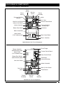
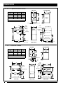
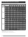
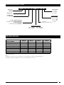
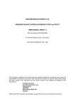
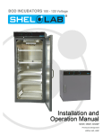
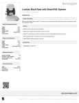
TECHNICAL SPECIFICATIONS
Model PGC2T (C and L) Series
SmartStart
®
M1200 Product Line
Two Stage, Fixed Speed ECM, High Efficiency
Upflow/Horizontal and Downflow Gas Furnaces
95.1 AFUE Input 60,000-120,000 Btuh
The high efficiency gas
furnace may be installed
free standing in a utility
room, basement, or
enclosed in an alcove or
closet. The rounded corner
jacket provides a pleasing
“appliance appearance.”
Design certified by CSA for
application in Canada and
the United States.
2
Features and Benefits
- i SEER — Energy efficient brushless DC (ECM) motor gives up
to 1 SEER point efficiency gain in cooling.
- 100% fired and tested — All units and each component are
tested on the manufacturing line.
- Best packaging in the industry — Unique corner post design
assures product will arrive to the homeowner dent free.
- 30 second blower delay at start-up assures a warm duct
temperature at furnace start-up. Adjustable blower off settings
(60, 90, 120 and 180 seconds).
- 30 second post purge increases life of heat exchanger.
- Hot surface igniter — Innovative application of an appliance
type igniter with a 20 year history of reliability. Utilizes proven
SmartStart® technology.
- Color coded wire harness — Designed to fit the components,
all with quick-connect fittings for ease of service and
replacement.
- Flexible category IV venting system — May be vertically or
horizontally vented using either a one-pipe or two-pipe system
for maximum flexibility in installation.
- High Static Blowers — All models equipped with high static
blowers.
- Low Boy Height — Easy to apply in low ceiling applications,
works well with taller high SEER coils, easier to handle and
install.
- Tubular primary heat exchanger — Heavy gauge aluminized
steel heat exchanger and stainless steel secondary heat exchanger
assures a long life.
- 90 second fixed cooling cycle blower-off delay (TDR) increases
cooling performance when matched with a NORDYNE coil.
- Variable Speed Blower Kit — Upgradable to full variable speed
with kit.
- LP convertible — Simple burner orifice and regulator spring
change for ease of convertibility.
- Diagnostic lights for easy troubleshooting without counting
flashes — Dedicated light for flame signal strength and 2 lights
in combination to indicate all other fault codes with easy to
recognize states without counting flashes.
- Incorporates integrated control board with connections for
electronic air cleaner and humidifier.
- Two piece door design enhances furnace appearance and uses
captured screws to prevent losing door screws.
- Blower Compartment — Sealed door to reduce air leakage and
insulated for ultra quiet operation.
- Sealed Vestibule reduces burner and inducer sound levels.
- 2 Stage Inducer — Optimizes efficiency on first stage heat and
reduces sound levels.
GAS FURNACE COMPONENTS
LOCATION OF FURNACE COMPONENTS
UPFLOW / HORIZONTAL FURNACE (*TC SERIES)
Flame
Sensor
Finish
Flange
Roll-Out
Switch
Burner
Assembly
Igniter
Pressure Switches
(Inducer)
AIR FLOW
Main Air Limit Switch
Gas Valve
Furnace Control Board
Inducer Limit Switch
Pressure Switches
(Condensate)
Transformer
Inducer Assembly
Blower Door Switch
Motor Control Box
Motor Choke
(C & D cabinets only)
1 2 34 5678
Motor Control Board
Blower Assembly
Upflow/Horizontal Gas Furnace Components
DOWNFLOW FURNACE (*TL SERIES)
Finish Flange
Blower Assembly
(behind blower panel)
Furnace Control Board
1 2 3 4 5 6 78
Motor Choke
(C & D cabinets only)
Blower Door Switch
(behind blower panel)
Vent Limit Switch
Motor Control Board
Transformer
Pressure Switches
AIR FLOW
Inducer Assembly
Main Air Limit Switch
Gas Valve
Igniter
Flame Sensor
Burner
Assembly
Roll-Out
Switch
Gas
Manifold
Downflow Gas Furnace Components
3
DIMENSIONS
*TC 95.1% Upflow/Horizontal Furnace
TOP VIEW
Dim.
“A”
‘B’ Cabinet
17 1/2
‘C’ Cabinet
21
‘D’ Cabinet
24 1/2
NOTES:
Dimensions shown in inches.
Dim.
“B”
15 7/8
19 3/8
22 7/8
Dim.
“C”
16 1/8
19 5/8
23 1/8
FL
AN
S
T-stat
(Ø 7/8)
A
Electric
(Ø 7/8)
Electric (Ø 7/8)
Vent pipe
(Ø 3”)
Gas
(Ø 1 5/8)
22 1/2
22 1/2
Gas (Ø 1 5/8)
17 7/8
24 7/8
Vent pipe
(Ø 3”)
17 1/4
Bottom
Panel
Combustion Air
T-stat
(Ø 7/8)
25 3/8
34 1/2
19
GE
3 1/4
2 3/4
22 1/2
C
Front Brace
23 1/2
Cabinet
Size
BOTTOM VIEW
B
1
4 Knockouts
(both sides)
15
Cond. (Ø 1 1/16)
28
23
Condensate
(Ø 1 1/16)
LEFT SIDE
FRONT VIEW
1 1/4
RIGHT SIDE
*TL 95.1% Downflow Furnace
Dim.
“A”
‘B’ Cabinet
17 1/2
‘C’ Cabinet
21
‘D’ Cabinet
24 1/2
NOTES:
Dimensions shown in inches.
Dim.
“B”
15 7/8
19 3/8
22 7/8
Dim.
“C”
16 1/8
19 5/8
23 1/8
BOTTOM VIEW
B
C
FL
Front
Brace
AN
GE
S
19
18 1/2
Cabinet
Size
TOP VIEW
Flue
3
Combustion
Air
7 1/2
Cond. (Ø 1 1/16)
LEFT SIDE
4
17 1/4
22 1/2
22 1/2
Vent pipe
(Ø 3”)
17 1/4
25 1/2
Gas (Ø 1 5/8)
10 1/4
34 1/2
22 1/4
Electric
(Ø 7/8)
Gas
(Ø 1 5/8)
22 1/4
25
Vent pipe
(Ø 3”)
22 1/2
25 3/8
Cond. (Ø 1 1/16)
FRONT VIEW
RIGHT SIDE
29 1/2
A
Electric
(Ø 7/8)
T-stat
(Ø 7/8)
17 7/16
28
25 1/4
BLOWER PERFORMANCE PGC2TC/TL
PGC2TC/TL - 95.1% AFUE, Two Stage Gas Furnace
Model Number
&
Heating Input
(Btuh)
*TC / TL - 060D
- 24B
(60,000)
*TC / TL - 80D
- 35C
(80,000)
External Static Pressure (in.W.C.)
Motor Switch Settings
(0 = OFF, 1 = ON)
0.1
0.2
0.3
0.4
0.5
0.6
0.7
0.8
1/5
2/6
3/7
4/8
CFM Rise CFM Rise CFM Rise CFM Rise CFM Rise CFM Rise CFM Rise CFM Rise
0
0
0
0
—
—
—
—
—
—
—
—
—
—
—
—
—
—
—
—
1
0
0
0
—
—
—
—
—
—
—
—
—
—
—
—
—
—
—
—
0
1
0
0
—
—
—
—
—
—
—
—
—
—
—
—
—
—
—
—
1
1
0
0
725
—
—
—
—
—
—
—
—
—
—
—
—
—
—
—
0
0
1
0
810
—
—
—
—
—
—
—
—
—
—
—
—
—
—
—
1
0
1
0
940
56
890
59
845
—
795
—
750
—
700
—
—
—
—
—
0
1
1
0
990
53
945
56
905
58
860
—
820
—
775
—
735
—
690
—
1
1
1
0
1,055
50
1,015
52
970
54
930
57
890
59
845
—
805
—
760
—
0
0
0
1
1,135
47
1,095
48
1,055
50
1,010
52
960
55
930
57
890
59
850
—
1
0
0
1
1,185
45
1,145
46
1,105
48
1,065
50
1,030
51
990
53
950
56
910
58
0
1
0
1
1,250
42
1,210
44
1,170
45
1,135
47
1,095
48
1,055
50
1,020
52
980
54
1
1
0
1
1,290
41
1,255
42
1,220
43
1,180
45
1,145
46
1,110
48
1,075
49
1,040
51
0
0
1
1
1,315
40
1,275
41
1,240
43
1,200
44
1,160
45
1,120
47
1,085
49
1,045
51
1
0
1
1
1,350
39
1,315
40
1,280
41
1,245
42
1,205
44
1,170
45
1,135
47
1,100
48
0
1
1
1
1,390
38
1,350
39
1,315
40
1,275
41
1,240
43
1,200
44
1,160
45
1,125
47
1
1
1
1
1,420
37
1,380
38
1,345
39
1,310
40
1,270
42
1,235
43
1,200
44
1,160
45
0
0
0
0
1,125
55
1,040
—
960
—
880
—
795
—
—
—
—
—
—
—
1
0
0
0
1,205
58
1,120
63
1,040
—
960
—
875
—
795
—
—
—
—
—
0
1
0
0
1,305
54
1,225
57
1,150
61
1,070
—
995
—
915
—
840
—
—
—
1
1
0
0
1,430
49
1,350
52
1,270
55
1,190
59
1,110
63
1,030
—
950
—
865
—
0
0
1
0
1,525
46
1,450
49
1,375
51
1,300
54
1,225
57
1,150
61
1,075
65
1,000
—
1
0
1
0
1,620
43
1,540
46
1,465
48
1,390
51
1,315
54
1,240
57
1,165
60
1,090
65
0
1
1
0
1,695
42
1,620
43
1,545
46
1,465
48
1,390
51
1,315
54
1,235
57
1,160
61
1
1
1
0
1,770
40
1,700
41
1,630
43
1,555
45
1,485
47
1,410
50
1,340
53
1,265
56
0
0
0
1
1,875
38
1,805
39
1,730
41
1,655
43
1,580
45
1,510
47
1,435
49
1,340
53
1
0
0
1
1,905
37
1,840
38
1,775
40
1,710
41
1,640
43
1,575
45
1,510
47
1,445
49
0
1
0
1
1,980
36
1,910
37
1,845
38
1,780
40
1,715
41
1,650
43
1,580
45
1,515
46
1
1
0
1
2,025
35
1,960
36
1,895
37
1,830
38
1,765
40
1,700
41
1,635
43
1,570
45
0
0
1
1
2,085
—
2,025
35
1,960
36
1,900
37
1,840
38
1,775
40
1,715
41
1,655
43
1
0
1
1
2,135
—
2,070
—
2,010
35
1,945
36
1,880
37
1,815
39
1,750
40
1,685
42
0
1
1
1
2,200
—
2,145
—
2,090
—
2,035
35
1,980
36
1,925
37
1,870
38
1,820
39
1
1
1
1
2,280
—
2,225
—
2,170
—
2,115
—
2,065
—
2,010
—
1,955
36
1,900
37
1. Motor Switch Settings are for heating speeds using HEAT switches 1, 2, 3, & 4 and cooling speeds using COOL switches 5, 6, 7, & 8.
2. Two openings are recommended for airflows above 1,600 CFM if the filter(s) is (are) adjacent to the furnace.
3. Data is shown without filter.
4. Temperature rises in the table are approximate. Actual temperature rises may vary
5. Cells shaded in gray indicate a temperature rise outside of the recommended range.
6. When in low stage, the circulating airflow is 70% of the tables high value (2-stage furnaces only).
5
BLOWER PERFORMANCE PGC2TC/TL CONTINUED
PGC2TC/TL - 95.1% AFUE, Two Stage Gas Furnace
Model Number
&
Heating Input
(Btuh)
*TC / TL - 100D
- 35C
(100,000)
*TC / TL - 120D
- 45D
(120,000)
External Static Pressure (in.W.C.)
Motor Switch Settings
(0 = OFF, 1 = ON)
0.1
0.2
0.3
0.4
0.5
0.6
0.8
1/5
2/6
3/7
4/8
CFM Rise CFM Rise CFM Rise CFM Rise CFM Rise CFM Rise CFM Rise CFM Rise
0
0
0
0
1,125
—
1,040
—
—
—
—
—
—
—
—
—
—
—
—
—
1
0
0
0
1,205
—
1,120
—
1,040
—
—
—
—
—
—
—
—
—
—
—
0
1
0
0
1,305
—
1,225
—
1,150
—
1,070
—
995
—
—
—
—
—
—
—
1
1
0
0
1,430
62
1,350
65
1,270
—
1,190
—
1,110
—
1,030
—
—
—
—
—
0
0
1
0
1,525
58
1,450
61
1,375
64
1,300
—
1,225
—
1,150
—
1,075
—
1,000 —
1
0
1
0
1,620
54
1,540
57
1,465
60
1,390
63
1,315
—
1,240
—
1,165
—
1,090 —
0
1
1
0
1,695
52
1,620
54
1,545
57
1,465
60
1,390
63
1,315
—
1,235
—
1,160 —
1
1
1
0
1,770
50
1,700
52
1,630
54
1,555
57
1,485
59
1,410
62
1,340
—
1,265 —
0
0
0
1
1,875
47
1,805
49
1,730
51
1,655
53
1,580
56
1,510
58
1,435
61
1,340 —
1
0
0
1
1,905
46
1,840
48
1,775
50
1,710
51
1,640
54
1,575
56
1,510
58
1,445 61
0
1
0
1
1,980
44
1,910
46
1,845
48
1,780
49
1,715
51
1,650
53
1,580
56
1,515 58
1
1
0
1
2,025
43
1,960
45
1,895
46
1,830
48
1,765
50
1,700
52
1,635
54
1,570 56
0
0
1
1
2,085
42
2,025
43
1,960
45
1,900
46
1,840
48
1,775
50
1,715
51
1,655 53
1
0
1
1
2,135
41
2,070
42
2,010
44
1,945
45
1,880
47
1,815
48
1,750
50
1,685 52
0
1
1
1
2,200
40
2,145
41
2,090
42
2,035
43
1,980
44
1,925
46
1,870
47
1,820 48
1
1
1
1
2,280
39
2,225
40
2,170
41
2,115
42
2,065
43
2,010
44
1,955
45
1,900 46
0
0
0
0
1,395
—
1,350
—
1,305
—
1,260
—
1,210
—
1,165
—
1,120
—
1
0
0
0
1,465
—
1,420
—
1,375
—
1,330
—
1,290
—
1,245
—
1,200
—
1,155 —
0
1
0
0
1,555
68
1,510
70
1,470
—
1,425
—
1,380
—
1,340
—
1,295
—
1,250 —
1
1
0
0
1,625
65
1,585
67
1,540
69
1,500
70
1,460
—
1,415
—
1,375
—
1,335 —
0
0
1
0
1,690
62
1,650
64
1,610
66
1,570
67
1,530
69
1,485
—
1,445
—
1,405 —
1
0
1
0
1,760
60
1,715
62
1,670
63
1,625
65
1,575
67
1,530
69
1,485
—
1,440 —
—
—
0
1
1
0
1,835
58
1,790
59
1,745
60
1,695
62
1,650
64
1,605
66
1,555
68
1,510 70
1
1
1
0
1,885
56
1,840
57
1,790
59
1,745
60
1,700
62
1,655
64
1,610
66
1,565 67
0
0
0
1
1,945
54
1,900
56
1,850
57
1,805
58
1,760
60
1,710
62
1,665
63
1,620 65
1
0
0
1
1,950
54
1,905
55
1,860
57
1,820
58
1,775
59
1,735
61
1,690
62
1,650 64
0
1
0
1
2,075
51
2,030
52
1,990
53
1,945
54
1,900
56
1,855
57
1,810
58
1,770 60
1
1
0
1
2,125
50
2,085
51
2,040
52
2,000
53
1,955
54
1,910
55
1,870
56
1,825 58
0
0
1
1
2,170
49
2,130
50
2,090
51
2,045
52
2,005
53
1,965
54
1,925
55
1,880 56
1
0
1
1
2,215
48
2,180
48
2,140
49
2,105
50
2,070
51
2,035
52
2,000
53
1,965 54
0
1
1
1
—
—
—
—
—
—
—
—
2,225
47
2,165
49
2,100
50
2,040 52
1
1
1
1
—
—
—
—
—
—
—
—
—
—
2,170
49
2,120
50
2,065 51
1. Motor Switch Settings are for heating speeds using HEAT switches 1, 2, 3, & 4 and cooling speeds using COOL switches 5, 6, 7, & 8.
2. Two openings are recommended for airflows above 1,600 CFM if the filter(s) is (are) adjacent to the furnace.
3. Data is shown without filter.
4. Temperature rises in the table are approximate. Actual temperature rises may vary
5. Cells shaded in gray indicate a temperature rise outside of the recommended range.
6. When in low stage, the circulating airflow is 70% of the tables high value (2-stage furnaces only).
6
0.7
IDENTIFICATION CODE
Maytag Gas
Compact
PGC
2
T
C
090 C
23 B
Cabinet Width
B = 17.50
C = 21.00
D = 24.50
Design Series
S = Single Stage
T = Two Stage
Cooling Airflow
23 = 2-3 Tons
24 = 2-4 Tons
35 = 3-5 Tons
45 = 4-5 Tons
C = Standard
V = VSB
D = 90+% AFUE Low NOx
A = 80% Upflow/Horizontal
C = 92.1% / 95.1% Upflow/Horizontal
K = 80% Downflow
L = 92.1% / 95.1% Downflow
Input Heating Capacity
060 = 60,000
080 = 80,000
100 = 100,000
120 = 120,000
SPECIFICATIONS
PGC2TC/PGC2TL
MODEL NUMBERS:
Input - Btuh (a)
Heating Capacity - Btuh
AFUE
Blower D x W
Motor H.P. - Speed - Type
Motor FLA
Rated Ext. SP - In. W.C.
Temperature Rise Range - ºF
Shipping Weights
060D24B
080D35C
100D35C
120D45D
60,000 / 39,000 80,000 / 52,000 100,000 / 65,000 120,000 / 78,000
57,000 / 37,050 76,000 / 49,400 95,000 / 61,750 114,000 / 74,100
95.1
95.1
95.1
95.1*
11 x 8
11 x 10
11 x 10
11 x 10
1/2 - BLDC
3/4 - BLDC
3/4 - BLDC
1 - BLDC
6.2
8.7
8.7
11.7
0.5
0.5
0.5
0.5
30-60
35-65
35-65
40-70
125lbs
135lbs
145lbs
160lbs
*TL 120 is 94.8% AFUE
Note: All models are 115V, 60 Hz. Gas Connections are 1/2" N.P.T. AFUE = Annual Fuel Utilization Efficiency
(a) Ratings to 2,000 ft. Over 2,000 ft. reduce 4% for each 1,000 ft. above sea level.
7
ACCESSORIES
PGC2T (C, L) KITS
Description
SKU
Fixed speed -to- variable speed
904880
2" Concentric vent kit
904177
3" Concentric vent kit
904176
"A" Cabinet downflow sub base kit
902974
"B", "C", "D" Cabinet downflow sub base kit
904911
2" Side wall vent kit
904617
3" Side wall vent kit
904347
U.S. LP Conversion kit (0 to 10,000 ft.)
904914
Canada LP Conversion kit (0 to 4,500 ft.)
904915
Bottom return filter 20 per box, "A" cabinet
903088
Bottom return filter 20 per box, "B" cabinet
904916
Bottom return filter 20 per box, "C" cabinet
904917
Bottom return filter 20 per box, "D" cabinet
904918
Side return filter kit
541036
Neutralizer kit
902377
VENTING
All models are approved for vertical non direct (1 pipe) and direct (2 pipe) venting applications. See Vent Table below for
specified sizes and allowable lengths.
FURNACE
MODELS
(BTU)
FURNACE
INSTALLATION
60,000
SINGLE PIPE LENGTH (FT.)
with 1 long radius elbow**
DIRECT VENT,
DUAL PIPE LENGTH (ft.) WITH
1 long radius elbow on each pipe**
INLET/OUTLET
INLET/OUTLET
2” Diameter
3” Diameter
90
90
50
90
30
90
Upflow
Horizontal
Downflow
OUTLET
2” Diameter
90
50
30
OUTLET
3” Diameter
90
90
90
80,000
Upflow
Horizontal
Downflow
40
30
30
90
90
90
40
30
30
90
90
90
100,000
Upflow
Horizontal
Downflow
30
30
30
90
90
90
30
30
25
90
90
90
120,000
Upflow
Horizontal
Downflow
N/A
N/A
N/A
90
90
90
N/A
N/A
N/A
90
90
90
*NOTES:
1. Subtract 2.5 ft. for each additional 2 inch long radius elbow, 5 ft. for each additional 2 inch short radius elbow, 3.5 ft. for each additional 3 inch
long radius elbow, and 7 ft. for each additional 3 inch short radius elbow. Subtract 5ft for each 2” tee and 8ft for each 3” tee.
2. Two 45 degree elbows are equivalent to one 90 degree elbow.
3. This table applies for elevations from sea level to 2,000 ft. For higher elevations, decrease pipe lengths by 8% per 1,000 ft of altitude.
Before purchasing this appliance, read important energy cost and efficiency
information available from your retailer. Specifications and illustrations subject
to change without notice and without incurring obligations.
Manufactured under license by NORDYNE, O’Fallon, MO. ®Registered Trademark/ TM Trademark
of Maytag Corporation or its related companies. ©2014. All rights reserved.
823C-0514 (Replaces 823C-0913)
Printed in U.S.A. (05/14)