1
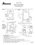
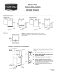
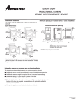
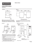
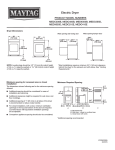
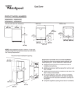
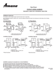
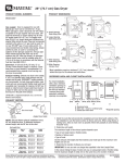
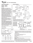
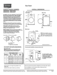
Electric Dryer
PRODUCT MODEL NUMBERS
MED3100D, MED4100D, MED5100D, MED7100D, MED8100D
Side view:
Front view:
27"
(686 mm)
383/4" Min.
(984 mm)
39" Max.
(990 mm)
Back view:
Recommended Installation Spacing:
61/2"
(165 mm)
NOTE: Most
installations
require a minimum
of 5" (127 mm)
clearance behind
dryer for exhaust
vent with elbow.
See “Venting
Requirements.”
18" min.
(457 mm)
Power supply
cord/cable
Water inlet
(Steam
models
5"
(127 mm)
61/8"*
(156 mm)
3
48 in.2 min.
(310 cm2)
297/8"*
(759 mm)
31/2"*
(89 mm)
Vent
/4"*
(18 mm)
3"
(76 mm)
143/8"
(365 mm)
3"
(76 mm)
1"
(25 mm)
24 in.2 min.
(155 cm2)
1"
(25 mm)
* Approx. measurement.
Installation spacing for recessed area or closet installation
The dimensions shown below are the recommended spacing for this dryer.
■■ Additional spacing should be considered for ease of installation and servicing.
■■ Additional clearances might be required for wall, door, floor moldings, and dryer venting.
■■ Additional spacing of 1" (25 mm) on all sides of the dryer is recommended to reduce noise transfer.
■■ For closet installation, with a door, minimum ventilation openings in the top and bottom of the door are required. Louvered
doors with equivalent ventilation openings are acceptable. Companion appliance spacing should also be considered.
W10676165A
04/2014
ELECTRICAL REQUIREMENTS
To supply the required 3 or 4 wire, single phase, 120/240 volt, 60 Hz., AC only electrical supply (or 3 or 4 wire, 120/208 volt electrical
supply, if specified on the serial/rating plate) on a separate 30-amp circuit, fused on both sides of the line. A time-delay fuse or circuit
breaker is recommended. Connect to an individual branch circuit.
VENTING REQUIREMENTS
Exhaust venting: Exhaust your dryer to the outside. 4" (102 mm)
diameter vent is required. Rigid or flexible metal exhaust vent
must be used. Do not use plastic or metal foil vet. Exhaust hood
must be at least 12" (305 mm) from the ground or any object that
may be in the path of the exhaust.
Exhaust hoods:
Recommended Styles:
Louvered Hood
Box Hood
The Vent System Chart provides venting requirements that will
help achieve best drying performance.
Vent System Chart
Number of
90° elbows
Type
of vent
Box/louvered
hoods
Angled
hoods
0
Rigid metal
64 ft. (20 m)
58 ft. (17.7 m)
1
Rigid metal
54 ft. (16.5 m)
48 ft. (14.6 m)
2
Rigid metal
44 ft. (13.4 m)
38 ft. (11.6 m)
3
Rigid metal
35 ft. (10.7 m)
29 ft. (8.8 m)
4
Rigid metal
27 ft. (8.2 m)
21 ft. (6.4 m)
Acceptable Style:
NOTE: Bottom exhaust installations have a 90º turn inside the
dryer. To determine maximum exhaust length, add one 90º turn
to the chart.
Angled Hood
Determine vent path:
■■ Select route that will provide straightest and most direct
path outdoors.
■■ Plan installation to use fewest number of elbows and turns.
■■ When using elbows or making turns, allow as much room
as possible.
■■ Bend vent gradually to avoid kinking.
■■ Use as few 90° turns as possible.
Determine vent length and elbows needed for best
drying performance:
■■ Use following Vent System Chart to determine type of vent
material and hood combinations acceptable to use.
NOTE: Do not use vent runs longer than those specified
in Vent System Chart. Exhaust systems longer than those
specified will:
■■ Shorten life of dryer.
■■ Reduce performance, resulting in longer drying times
and increased energy usage.
Because Whirlpool Corporation policy includes a continuous commitment to improve
our products, we reserve the right to change materials and specifications without notice.
Dimensions are for planning purposes only. For complete details, see Installation
Instructions packed with product. Specifications subject to change without notice.