1
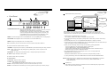
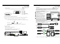
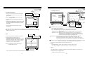
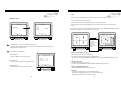
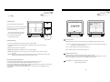
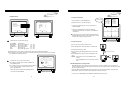
Thank you for purchasing our product.
Please read this User s Manual before
using the product.
Half-duplex audio supported
4 Channel Digital Video Multiplex Recorder
4 CH STAND-ALONE DVMR
ALL ABOUT IMAGE RECOGNITION & PROCESSING
DIGITAL VIDEO
DIGITAL VIDEO RECORDER
RECORDER
User s Manual VER 1.0
The most stable and reliable real stand-alone Digital Video Multiplex Recorder
ALL ABOUT IMAGE RECOGNITION & PROCESSING
ALL ABOUT IMAGE RECOGNITION & PROCESSING
SAFETY PRECAUTIONS
CAUTION
RISK OF ELECTRIC
SHOCK. DO NOT OPEN!
CAUTION : TO REDUCE THE RISK OF ELECTRICAL SHOCK, DO NOT OPEN COVERS.
NO USER SERVICEABLE PARTS INSIDE. REFER SERVICING TO QUALIFIED
SERVICE PERSONNEL.
This label may appear on the bottom of the unit due to space limitations.
The lightning flash with an arrowhead symbol within an equilateral triangle is intended
to alert the user to the presence of uninsulated “ dangerous voltage” within the
product’s enclosure that may be of sufficient magnitude to constitute a risk of electric
shock to persons.
The exclamation point within an equilateral triangle is intended to alert the user to
presence of important operating and maintenance (Servicing) instructions in the
literature accompanying the appliance.
WARNING : TO PREVENT FIRE OR SHOCK HAZARD, DO NOT EXPOSE UNITS NOT
SPECIFICALLY DESIGNED FOR OUTDOOR USE TO RAIN OR MOISTURE.
Attention: installation should be performed by qualified service Personnel only in
accordance with the National Electrical Code or applicable local codes.
Power Disconnect. Units with or without ON-OFF switches have power supplied to
the unit whenever the power cord is inserted into the power source ; however, the unit
is operational only when the ON-OFF switch is in the ON position. The power cord is
the main power disconnect for all unites.
ALL ABOUT IMAGE RECOGNITION & PROCESSING
ALL ABOUT IMAGE RECOGNITION & PROCESSING
ALL ABOUT IMAGE RECOGNITION & PROCESSING
FCC INFORMATION
4. Arrangement RS-232C pin
RS-232C
A CLASS A computing device subject to certification by the Commission shall be identified pursuant to
par.2.925 et Seq of the chapter. In addition, the label shall include the following statement:
Pin No.
Definition
1
NC
2
RxD
3
TxD
4
NC
C o m m
P o rt
1
5
GND
6
NC
7
NC
8
NC
9
NC
This device complies with Part 15 of the FCC Rules.
Operation is subject to the following two conditions:
(1)This device may not cause harmful interference, and
(2)This device must accept any interference received,
including interference that may cause undesired operation.
5
6
9
RS-232C
Where a device is constructed in two or more sections connected by wires and marketed together, the
statement specified in this Section is required to be affixed only to the main control unit.
The users manual or instruction manual for the EUT shall contain the following statement or eqivalent.
DVMR unit
Other device (PC)
Caution : Changes or Modifications not expressly approved by the party responsible for compliance could
void the users authority to operate the equipment.
D-SUB 9 cable (twisted RS-232C cable)
#2
RxD
RxD
#2
#3
TxD
TxD
#3
#5
GND
GND
#5
If the EUT requires accessories such as special shielded cables and/or connectors to enable compliance
with emission limits, the instruction manual for the EUT shall include appropriate instructions on the first
page of the text concerned with the installation of the device that these special accessories must be used
with the device. It is the responsibility of the user to use the needed special accessories supplied with the
equipment.
For a CLASS A digital device or peripheral, the instructions furnished the user shall include the following or
similar statement placed in a prominent location in the text of the manual.
Note : This equipment has been tested and found to comply with the limits for a CLASS a digital device,
pursuant to Part 15 of FCC Rules. These limits are designed to provide reasonable protection against
harmful interference when the equipment is operated in a commercial environment. This equipment
generates, uses and can radiate radio frequency energy and, if not installed and used in accordance with
the instruction manual, may cause harmful interference to radio communications. Operation of the this
equipment in a residential area is likely to cause harmful interference in which case the user will be required
to correct the interference at his own expense.
31
ALL ABOUT IMAGE RECOGNITION & PROCESSING
ALL ABOUT IMAGE RECOGNITION & PROCESSING
6. Specification and
Configuration
2. Configuration
Table of Contents
TCP/IP
1.About this document
Camera #1~4
2
Sensor
2. Before reading this document
2
3. Unit Description
3
Remote
Controller
Alarm
TCP
/IP
RS-232C
1) Front Panel
2) Rear Panel
Printer
3
4
4. Installation
5
5. Operation
9
1) Log-in
2) Record
3) Play
4) Setting
1 Basic Operation
2 DISPLAY SETUP
3 CAMERA SETUP
4 TIME/DATE SETUP
5 ALARM/MOTION SETUP
6 RECORD SETUP
7 TCP/IP SETUP
8 MISCELLANEOUS SETUP
P/T Camera RX Box
9
10
13
15
15
16
17
19
20
23
24
25
1) SPECIFICATIONS
2) Stand alone DVMR
3) RS-232C Hex-codes table
4) Arrangement RS-232C pin
29
30
30
31
TV Monitor
S-Video Monitor
Video
Printer
3. RS-232C Hex-codes table
Following ASCII-codes are for programmers who want to control the DVMR via RS-232C port.
RS-232C specification (baud rate/parity/data length/stop bit) : 19200, N, 8, 1
1 Byte ASCII-code.
MENU
‘M’
PIP/
MARK
‘I’
CH1
‘1’
UP
‘U’
PLAY
‘P’
FRZ
‘F’
CH2
‘2’
DN
‘J’
MODE
‘D’
SEQ/
SPEED
‘Q’
CH3
‘3'
LEFT
‘H’
PANTILT
‘T’
ZOOM
‘Z’
CH4
‘4’
RIGHT
‘K’
29
6. Specification & Configuration
VCR
DEFAULT KEY ‘0’ (Default setup: Displays and records on Quad mode)
30
1
ALL ABOUT IMAGE RECOGNITION & PROCESSING
ALL ABOUT IMAGE RECOGNITION & PROCESSING
6. Specification and
configuration
1. SPECIFICATIONS
Before installing stand alone DVMR, be sure to thoroughly review and follow the instructions in this
MODEL NO
Stand alone DVMR
INPUT
OUTPUT
VIDEO I/F
HORIZONTAL RESOLUTION
S/N RATIO
COLOR
MONITORING
METHOD
4 CH INPUT 1.0 VP-P, 75 OHM UNBALANCED (BNC TYPE)
3 OUTPUT VBS : 1.0VP~P.75 OHM UNBALANCED (BNC TYPE)
480TV LINES
FULL, QUAD DISPLAY
LIVE & PB AVAILABLE
PIP
AVAILABLE
SEQUENCE
AVAILABLE
FULL : 720(H)X480(V) ACTIVE PIXELS
1/4 SCREEN : 360(H)X240(V) ACTIVE PIXELS
PICTURE RECORDING
METHOD
2. This manual contains information for configuring, managing and using stand alone DVMR Model.
DUPLEX(PLAYBACK/RECORDING)
REC, MODE
REAL-TIME/ TIME-LAPSE / EVENT
4. Be sure to read this manual before using stand alone DVMR Model.
TRACK PLAY
SEARCH, STILL
TCP/IP with client software
5. For questions and technical assistance of this product, contact your local dealer.
1~59SEC, CONTINUOUS TIMING ESTABLISHMENT POSSIBILITY
BACK-UP
CONVENTIONAL VCR, TIME LAPS VCR (VCR OUTPUT PROVIDED)
REMOTE BACK-UP USING TCP/IP
INTERNAL BACK-UP(MARK IMAGE)
OTHERS
RS232C, RS485, MAX 4 ALARM INPUT
Strong recommendation on installation of the DVMR unit
PAN/TILT/ZOOM AND FOCUS
REMOTE CONTROL : EXTERNAL EQUIPMENT, WIPER,PUMP,FAN AND
HEATER
1. Check electricity at the place you want to install the DVMR unit is stable and meets our
electricity requirements.
Unstable electricity will cause malfunction of the unit or give critical damage to the unit.
CAMERA CONTROL
CONFIGURATION
PLUG&PLAY
2 HDD
INTERNAL 1 OR 2 HDD
ACCEPT MIXED USAGE OF HDD FROM DIFFERENT MANUFACTURERS
Input
4CH INPUT 1.7VP-P, 47K OHM UNBALANCED (MONO PHONE JACK)
Output
1 OUTPUT, 3.4VP-P, 600 OHM UNBALANCED (MONO PHONE JACK)
OPERATION TEMPERATURE
OPERATION HUMIDITY
MECHANICAL
1. This document is intended for both the administrator and users of stand alone DVMR Model.
3. To prevent fire or electrical shock, do not expose the product to heat or moisture
WEB INTERFACE
AUDIO
2. Before reading this document
QUAD SCREEN RECORDING
FIELD SWITCHER METHOD FULL SCREEN RECORDING
POST ALARM FUNCTION
OTHER
FUNCTION
instruction for appropriate installation.
0.1~30 FRAME/SEC (EACH CHANNEL)
JPEG
SIMPLEX/DUPLEX
Also, when connecting with external application, first turn the power OFF and follow manual
16.7 MILLION
ZOOM
SPEED
User’s Manual. Pay particular attention to the parts that are marked NOTICE.
MORE THAN 4dB
SPLIT SCREEN
SCREEN QUALITY
RECORDING
/PLAY
FUNCTION
1. About this document
IR REMOTE CONTROLLER
DIMENSION
WEIGHT
POWER SUPPLY
41F~ 104F (5C~ +40C)
2. Several chips on the main board of the DVMR unit and hard disk drive inside the unit generate
heat, and it must be properly discharged.
Do not put any objects just beside exhaust port(fan) on the left side of the unit and do not close
up an opening (fresh air in-take) on the right side of the unit..
3. Put the DVMR unit at well-ventilated place and do not put heat-generating objects on the unit.
When it is installed inside 19 inch mounting rack together with other devices, please check builtin ventilation fan of the rack is properly running.
LESS THAN 90%
BUILT-IN
13 INCHES IN WIDTH 445 mm x 415 mm x 130 mm
APPROX. 5KG (HDD 1EA)
DC ADAPTER29(12V DC 4.5A)
2
ALL ABOUT IMAGE RECOGNITION & PROCESSING
ALL ABOUT IMAGE RECOGNITION & PROCESSING
3. Unit Description
5. Operation
6
MARK IMAGE SETUP (Internal backup)
1. Front Panel
1
POWER
Indicates the start and end
location of stored images.
6
14
13
MARK IMAGE SETUP
Indicates the number of stored
images.
TOTAL SAVE FRAME
START MARK TIME
----/--/-- --/--/-EMD MARK TIME
----/--/-- --/--/-DELETE MARK IMAGE
PLAY MARK IMAGE
SYSTEM SETUP
OVERWRITE
AUD
1
2
3
4
P/T
PIP
FRZ
SEQ
ZOOM
DISPLAY SETUP
CAMERA TITLE
TIME/DATE SETUP
ALARM/MOTION
SETUP
RECORD SETUP
TCP/IP SETUP
MISCELLANEOUS
FACTORY DEFAULT
RECORD
PLAY
MENU
SETUP
PLAY
MODE
ENTER
2
3
SPEED
MARK
4
5
7
8
9
10
11
12
1. POWER SWITCH WITH LED : DC power switch with LED
Before you turn off DC power switch off, we strongly recommend you to press
[MENU] button first to make HDD not in writing process.
Generally speaking, cutting power to system may cause trouble in DVMR
system or damage to HDD if HDD is in writing process, and we ask you to
press [MENU] button first to protect HDD from being damaged or system
failure before you press DC power switch off in practical operation.
2. MENU : Used when changing the menu of SYSTEM SETUP. If you press [MENU] button, recording stopped.
BUZZER SETUP
ID/PW SETUP
SCHEDULE REC
SETUP
PANTILT CMD SETUP
HDD INFORMATION
MARK IMAGE SETUP
PRODUCT ID
0
Deletes or replay marked images.
SELECT
, PRESS ENTER
MARK IMAGE SETUP
MARK IMAGE is very useful function, because it protects marked images from being overwritten.
During playback, you can mark images to store them on HDD separately from normal pictures. Those
marked pictures are not deleted even though you clear data on HDD or even after HDD starts to overwrite.
1) While replaying, press [MARK] button to select images.
Then“PAUSE”, “SPEED” and “MARK” are displayed on top of the screen.
3. PLAY/ENTER : Starts playback, and in some functions, it is used as the SELECT key.
2) In this mode (paused mode), press [LEFT] or [RIGHT] button to select frames you want to mark as many
as wanted.
4. MODE : Changes to quarterly split screen or Full display screen.
3) Press [MARK] button once more to complete MARK IMAGE SETUP for images you selected.
5. P/T : Select built-in protocol for PTZ camera and control PTZ camera connected to DVMR unit
4) Therefore all images between first [MARK] button and second [MARK] button remain not deleted unless you
delete marked image on purpose in MARK IMAGE SETUP.
6. 1,2,3,4 : Chooses each indicated channel or camera.
7. PIP/MARK : Assigns PIP (Picture in picture) or MARK IMAGE to protect selected image from being overwritten.
8. FRZ : : Display screen is paused. By pressing [LEFT] or [RIGHT] button, it moves to previous or next
image field by field.
9. SEQ/SPEED : The display screen automatically rotates, or assigns playback speed and direction.
5) When you want to mark large amount of images, cancel PAUSE by pressing [FRZ] button.
That is, press [FRZ] button, and search images replayed in actual speed.
Then press [MARK] again to complete MARK IMAGE SETUP.
All images between first [MARK] button and second [MARK] button remain not deleted unless you
delete marked image on purpose in MARK IMAGE SETUP.
6) If the MARK IMAGE space given in the HDD gets to be full, “FULL” message appears and
[MARK] button does not work any more.
10. ZOOM : Enlarges the display screen by 200%
(HDD space for MARK IMAGE : stores about 10 minutes in normal picture taking-condition.)
7) To replay marked image, select PLAY MARK IMAGE, and to delete select DELETE MARK IMAGE.
11. Remote Controller Sensor Input Window
12. Direction button
NOTICE : Marked images stored on dedicated part of HDD, allocated just for MARK IMAGE, is not deleted
unless “HDD CLEAR” is activated. It can be erased only by DELETE MARK IMAGE, in
MARK IMAGE SETUP.
13. LED Lamps : Represent status of operation
14. AUDIO : Select channel for audio playback
Press [AUDIO] button and then channel number, any one of 4, to hear audio
NOTICE : If the Input window (IR receiver) is covered, the remote controller may not work.
NOTICE : If several buttons are simultaneously or incorrectly pressed, the system may not function properly.
3
7
PRODUCT ID
Serial number of products. Necessary for manufacturer to know manufacturing date, program version
number, and others for after sales service.
28
ALL ABOUT IMAGE RECOGNITION & PROCESSING
01:00-03:00 ON
04:00-05:00 ON
ALL ABOUT IMAGE RECOGNITION & PROCESSING
3.Unit Description
5. Operation
Just record from 1 to 3 and from 4 to 5, and does not record for the rest hours.
01:00-03:00 OFF
04:00-05:00 OFF
2. Rear Panel
Not record from 1 to 3 and from 4 to 5, and records for the rest hours.
01:00-03:00 ON
04:00-05:00 OFF
3
4
7
5
9
Just record from 1 to 3 (When both ON and OFF are set, priority is on ON.)
FUNCTION
6
1 RS 485 D2 RS 485 D+
7
3 RELAY COM 8
4 RELAY NC
9
5 RELAY NO 10
ALARM GND
ALARM D4
ALARM D3
ALARM D2
ALARM D1
SPK
MIC4
MIC3
MIC2
MIC1
AUDIO
ETHERNET
CH1
CH2
CH3
CH4
VCR
RS-232C
4 PANTILT COMMAND SETUP : When PTZ camera whose protocol is already incorporated into this DVMR
system (Default PTZ camera) is connected to this DVMR, just select model of PTZ camera in
PANTILT COMMAND SETUP. If user want to connect PTZ camera which is not one of Default PTZ
camera, users must input protocols of PTZ camera or speed dome camera by themselves in USER
DEFINE SETUP.
For detail procedure, refer to manual for incorporating protocol of PTZ camera into DVMR system.
SYSTEM SETUP
DISPLAY SETUP
CAMERA TITLE
TIME/DATE SETUP
ALARM/MOTION SETUP
RECORD SETUP
TCP/IP SETUP
MISCELLANEOUS
FACTORY DEFAULT
1. DRX-502A
2. AECD-2000
3. HMC-250
4. PELCO D TYPE
3.USER DEFINE
PANTILT COMMAND SETUP
V
G
A
DC 12V
1
2
3
4
5
1
6
7
8
9
MONITOR
LOOP
10
2
6
8
10
11
1. RS-232C Port Connection
2. PAN/TILT Controller, Sensor Input/Output
3. AUDIO : 4 Input and 1 output
COMMAND TYPE : USER DEFINE
485 BAUDRATE : 9600 BPS
USER DEFINE SETUP
BUZZER SETUP
ID/PW SETUP
SCHEDULE REC
SETUP
PANTILT CMD SETUP
HDD INFORMATION
MARK IMAGE SETUP
PRODUCT ID
Comm Port
3. NOTE for scheduled recording :
When scheduled recording is set, DVMR unit does not record before the set time. It only starts recording at
START time and ends at END time.
4. LAN (TCP/IP)
5. Camera Connection
SELECT
, PRESS ENTER
6. LOOP Output
7. VCR Connection
PAN/TILT COMMAND SETUP
Procedure to control PTZ camera while you see live picture
1. Default PTZ camera : First select PTZ camera model connected to DVMR unit in the PANTILT COMMAND
SETUP menu. In live view mode, press [P/T] button and set CAM (Starts from 000) at camera ID which
is set on PTZ camera (DIP switch on PTZ camera) before you connect it to DVMR unit. Then select
command you want to execute using [LEFT] and [RIGHT] buttons. While you press [PLAY] button,
command you selected is executed.
2. USER DEFINE : In case you input protocols of PTZ camera which is not one of Default cameras, select
USER DEFINE in PANTILT COMMAND SETUP. Then press [P/T] button and set CAM (Ranges from
001 to 004) at any one from 001 to 004. CAM number must be the same as CH number which you set
when you input protocol of PTZ camera in USER DEFINE. Using [LEFT] and [RIGHT] button, select
command you want to execute and press [PLAY] button to execute selected command. While you press
[PLAY] button, command you selected is executed.
8. MONITOR Connection
9. VGA Connection
10. S-VHS Connection
11. D/C Power Connection
NOTICE : When connecting with other applications, be sure to turn off the system.
5 HDD INFORMATION
HDD DATA LIST : Shows general information of HDD.
HDD AUTO DETECT : Allows to detect HDD just in case first HDD search after purchase failed.
27
4
ALL ABOUT IMAGE RECOGNITION & PROCESSING
4. Installation
ALL ABOUT IMAGE RECOGNITION & PROCESSING
3
5. Operation
SCHEDULE REC SETUP :
▶ Procedure
SCHEDULE REC SETUP
1) Camera Connection
SYSTEM SETUP
DISPLAY SETUP
CAMERA TITLE
TIME/DATE SETUP
ALARM/MOTION
SETUP
RECORD SETUP
TCP/IP SETUP
MISCELLANEOUS
FACTORY DEFAULT
Connect the camera to the CAMERA INPUT on the Rear Panel of the system.
DATE : Set by day
WEEK : Set by a day
of the week
BUZZER SETUP
ID/PW SETUP
SCHEDULE REC SETUP
PANTILT CMD SETUP
HDD INFORMATION
MARK IMAGE SETUP
PRODUCT ID
YY-MM-DD
02-07-06
SAT
02-07-07
SUN
02-07-08
MON
02-07-09
TUE
START
00:00
00:00
00:00
00:00
00:00
00:00
00:00
00:00
MODE : DATE
SELECT
-
,
END
24:00
24:00
24:00
24:00
24:00
24:00
24:00
24:00
ON/OFF
ON
ON
ON
ON
ON
ON
ON
ON
RESET : NONE
ENTER OR MODE
NONE : No reset
DATE : Reset selcted
date only
All : Reset all.
DC
LEVEL
V.P
VIDEO
CH2
CH3
CH4
VCR
CommPort
CH1
DC
V
G
A
VIDEO
LENS
AC24V/DC12
MONITOR
LOOP
Rear part of CAMERA
Notice : This DVMR system automatically detects video system of camera you connected
to the unit when you boot DVMR system first. It is not necessary to set video
system separately, and DVMR system set at NTSC or PAL system automatically
when you boot the system.
SCHEDULE REC SETUP
Records according to schedule by day or a day of the week. Two recording time spans can be set for a
day and a day of the week respectively. In total, 4 recording time spans can be set in a day.
DVMR system records just as you set if you set SCHEDULE REC SETUP, and DVMR system records 24
hours a day if you do not set SCHEDULE REC SETUP.
1. Scheduled Recording for a day:
1) Press ENTER button to enter into SCHEDULE REC SETUP menu. In the sub-menu, you are requested
to select MODE or RESET. To first set up, select DATE or WEEK by pressing [ENTER] button.
2) Press [MODE] button to be ready for editing. Then move to the location for change using direction button.
3) Set recording time for START and END with [ENTER] button. Recording time increases by 30 minutes
whenever [ENTER] button is pressed.
4) After set START and END time for a day and set ON/OFF using [ENTER] button.
If you set ON, it means DVMR system records in time span you set. If you set OFF, DVMR system
stop recording in the time span you set.
2) Monitor Connection (Composite Connection Method)
Connect the monitor to the MONITOR OUT on the Rear Panel of the system
5) After set all data, press [MODE] button once more to memorize settings you set in the system.
6) RESET is used to delete previously set recording schedule.
CH2
CH3
LOOP
CH4
VCR
CommPort
CH1
V
G
A
Select DATE, and move to the date by pressing [MODE] button, and press [ENTER] button to delete.
ALL deletes all recording schedule.
MONITOR
VIDEO A
VIDEO B
VIDEO C
IN
IN
IN
OUT
OUT
OUT
(NONE : Does not reset
DATE : deletes only selected date
ALL : deletes all)
7) When all input is ended, press [MENU] button to come back to SCHEDULE REC SETUP.
NOTICE : To move the cursor in SCHEDULE RECORD SETUP menu , RESET should be set at NONE.
2. Scheduled recording by a day of the week :
Notice : Connect camera or monitor to DVMR unit while DC power switch on the front panel
is off.
Recording is activated on a day of the week at the time set in advance. To set schedule for a day of the week,
first select WEEK in MODE of SCHEDULE REC SETUP by pressing [ENTER] button.
5
Set recording time for each day of the week as the procedure for Scheduled Recording for a day.
26
ALL ABOUT IMAGE RECOGNITION & PROCESSING
5. Operation
8. MISCELLANEOUS SETUP
1
ALL ABOUT IMAGE RECOGNITION & PROCESSING
4. Installation
BUZZER SETUP : Sets different kinds of BUZZER ON/OFF.
BUZZER SETUP is available for each group as follows.
SYSTEM BUZZER : All of followings
BUTTON BUZZER : Buzz when button is pressed
ALARM BUZZER : Buzz when alarm is activated
MOTION BUZZER : Buzz when motion is detected
LOSS BUZZER : Buss when video is lost
You can set all buzzer at ON or OFF at once by setting
SYSTEM BUZZER or each group of BUZZER
independently by setting from BUTTON BUZZER to
LOSS BUZZER one by one. Any way, BUZZER is
activated just in case you set at ON in corresponding
group of BUZZER SETUP.
MISCELLANEOUS SETUP
1
BUZZER SETUP
ID/PW SETUP
SCHEDULE REC SETUP
PANTILT CMD SETUP
HDD INFORMATION
MARK IMAGE SETUP
PRODUCT ID
SELECT
2
3
4
5
6
7
3) Monitor (S-VHS) Connection
, PRESS
Connect S-VIDEO Monitor to MONITOR OUT(S-VHS) on the Rear Panel of the system.
MISCELLANEOUS SETUP
2
ID/PW SETUP : Sets User ID and PASSWORD.
Only in case you entered
into SETUP menu with
ADMIN ID, you can
change all settings
including recording
parameters.
CH1
CH2
SYSTEM SETUP
DISPLAY SETUP
CAMERA TITLE
TIME/DATE SETUP
ALARM/MOTION SETUP
RECORD SETUP
TCP/IP SETUP
MISCELLANEOUS
FACTORY DEFAULT
1,2,3,4
MARK
PW
PW
PW
<
<
<
<
CH4
VCR
USER
>
>
>
>
V
G
A
VIDEO
A
IN
OUT
VIDEO
B
IN
OUT
VIDEO
C
IN
MONITOR
LOOP
ID/PW SETUP
ID
CURRENT
NEW
CONFIRM
CH3
CommPort
If you enter into SETUP menu with USER ID, you have
a certain limitation in parameter setting.
You can not change setting fro recording or other
important parameters with USER ID.
4) VCR & VIDEO PRINTER Connection
: INPUT PASSWORD
: ERASE PASSWORD
Connect VCR or VIDEO PRINTER to VCR OUT on the Rear Panel of the system.
BUZZER SETUP
ID/PW SETUP
SCHEDULE REC SETUP
PANTILT CMD SETUP
HDD INFORMATION
MARK IMAGE SETUP
PRODUCT ID
SELECT
, PRESS ENTER
ID/PW SETUP
VCR
1) In ID/PW SETUP, first select kind of ID, that are, USER or ADMIN, by pressing [ENTER] button.
CH1
CH2
CH3
LOOP
CH4
VCR
CommPort
2) With [UP] and [DOWN] button, move to CURRENT PW and press [ENTER] button and then input current
password. After input password, press [ENTER] button again.
Then move to NEW PW by pressing [DOWN] button. And press [ENTER] to input new password to which
you want to change. Then press [ENTER] button.
Then move to CONFIRM PW and input new password again to confirm it.
V
G
A
MONITOR
VIDEO PRINTER
3) Password you will input must consist of 1 to 8 digits number and each digit is from 1 to 4. You can not
use other buttons on the front panel for password.
Notice : In the very first setup stage, the ADMIN PASSWORD is “1”, and USER PASSWORD is “2”.
Change PASSWORD as soon as this product is purchased.
25
6
OUT
ALL ABOUT IMAGE RECOGNITION & PROCESSING
ALL ABOUT IMAGE RECOGNITION & PROCESSING
4. Installation
5. Operation
7. TCP/IP SETUP
5) Sensor Connection
TCP/IP option of this DVMR system enables user to see live pictures and recorded pictures via internet
line, far apart from DVMR unit. To see live pictures or recorded pictures of DVMR, users must assign IP
address into DVMR together with Gateway and Subnet mask first, and then install Remote Viewer
Program included in the package on client PC.
For detail procedure for installing Remote Viewer Program and setting up, refer to manual for Remote
Viewer program included in the package.
Connect the Sensor to the SENSOR INPUT/OUTPUT on the Rear Panel of the system
Terminal block
RELAY
ALARM
D D C N N G D D D D
-- + O C O N 4 3 2 1
D
M
Pin 1
Pin 2
Pin 3
Pin 4
Pin 5
Pin 6
Pin 7
Pin 8
Alarm1
Alarm2
Alarm3
Alarm4
GND
NO( Normal Open )
NC( Normal Close)
COM
COM NC NO GND D4 D3 D2 D1
1
IP ADDRESS : Enter numbers using direction buttons and
press [MENU] button.
SYSTEM SETUP
3 SUBNET MASK : Enter numbers using
direction buttons and press [MENU] button.
Relay output : COM+NC, COM+NO OR COM+NC+NO
Alarm input : Short-circuit between Alarm1, Alarm2, Alarm3 or Alarm4 and GND is recognized as alarm.
NOTICE : Sensor input is RECOGNIZED as LOW when alarm signal is on a level with GND,
and it is recognized as HIGH when alarm signal is FLOATING or 5V. Following is internal circuit.
5
V
D1
Internal Circuit
Thus, there is a danger of damage, when the sensor input goes to a Negative level or
voltage higher than 5V.
4 MAC ADDRESS : It is unique ID number
provided by the manufacturer, and the user
should not change under any condition.
RS 485 : Connect to PTZ camera
AUDIO : 1 audio input/channel, 1 audio output from selected channel.
PC
Client program
(remote viewer)
PTZ
CAMERA
MIC3
MIC2
PC
Client program
(remote viewer)
MIC1
AUDIO
ETHERNET
RS-232C
1
DVMR unit
LAN, WAN, or Internet
2
3
4
5
6
7
8
9
10
For more details, refer to arrangements RS-232c pins in page 32.
7
5
, PRESS ENTER
PC
LAN
Internet
Internet
PTZ
Camera
TCP/IP setup
Router/Gateway
IP Sharer
b) Accessing to DVMR unit via Internet line
PC
Client program
(remote viewer)
MIC4
SELECT
2
3
4
1) Concept of accessing to DVMR unit via IP network
RJ-45 (ETHERNET) : Connect to LAN, WAN or Internet
SPK
1
IP ADDRESS
GATEWAY
SUBNET MASK
MAC ADDRESS
DHCP SETUP
5 DHCP SETUP : In case you connect DVMR
unit to LAN network under router/Gateway/IP
sharer which has DHCP server function, set
DHCP SETUP at DHCP, and DVMR unit automatically gets
TCP/IP SETUP
IP data automatically during the process of booting.
In case you connect DVMR unit to leased line with static IP, Router/Gateway connected ADSL(with
static IP or dynamic IP), you are requested to set DHCP at MANUAL and input IP data manually. For
details, refer to Remote Viewer manual.
DHCP server
RS-232C : Connect to PC to operate DVMR
ALARM GND
ALARM D4
ALARM D3
ALARM D2
ALARM D1
DISPLAY SETUP
CAMERA TITLE
TIME/DATE SETUP
ALARM/MOTION SETUP
RECORD SETUP
TCP/IP SETUP
MISCELLANEOUS
FACTORY DEFAULT
2) Conditions of IP network
a) Accessing to DVMR unit in the same Intranet(LAN)
6) Network Connection
FUNCTION
1 RS 485 D6
2 RS 485 D+ 7
3 RELAY COM 8
4 RELAY NC 9
5 RELAY NO 10
TCP/IP SETUP
2 GATEWAY : Enter numbers using direction
buttons and press [MENU] button.
DHCP SETUP
DVMR unit
Automatic
Leased line w/ static IP
Cable modem w/ dynamic IP
ADSL
modem
w/
dynamic IP
24
or
static IP
Router
or
Gateway
DHCP SETUP
DVMR unit
Leased line : Manual
Cable modem : Automatic
DHCP SETUP
DVMR unit
Manual
Other devices
Port Forwarding
PPPoE
(IP Forwarding)
protocol
For details of TCP/IP setting in DVMR unit and PC, refer to “Remote Viewer manual” included in the package.
24
ALL ABOUT IMAGE RECOGNITION & PROCESSING
6. RECORD SETUP
5. Operation
RECORD SETUP is one of the most important settings in DVMR
system. In this menu, you can select simplex operation or semiduplex operation with a certain ratio between playback and
recording.
SYSTEM SETUP
The difference between
DISPLAY SETUP
SIMPLEX and SEMICAMERA TITLE
DUPLEX (selected with a
TIME/DATE SETUP
ALARM/MOTION
certain ratio between
SETUP
HDD CLEAR
RECORD SETUP
playback and recording)
HDD FULL
TCP/IP SETUP
operation is as follows.
RECORD MODE
MISCELLANEOUS
FACTORY DEFAULT
1
2
3
4
5
6
7
8
ALL ABOUT IMAGE RECOGNITION & PROCESSING
RECORD TYPE
RECORD SPEED
4. Installation
7) HDD connection
RECORD SETUP
HDD CLEAR
HDD FULL
RECORD MODE
RECORD TYPE
RECORD SPEED
PRIORITY MODE
DUPLEX RATIO
AUDIO RECORD
:
:
:
:
:
:
:
:
NO
OVERWRITE
TIMER
FIELD
60FPS
NONE
PLAY 1 : REC 1
ON
1
2
3
4
5
6
7
8
Simplex : recording stopped
PRIORITY MODE
in playback
SELECT
, PRESS
Semi-duplex : Minimum numbers of images from each channel
as per selected ratio recorded while it is in playback mode, even
though both playback speed is lower than simplex operation or
recording speed in playback is 10 to 20 fields/ sec in total. It is
RECORD SETUP
very important that DVMR system records several images from
each channel during playback mode, if we set it at Semi-duplex mode(set DUPLEX RATIO).
HDD CLEAR : To delete all data on HDD, select YES and press [MENU] button and [ENTER] button.
Notice : All contents of the HDD is deleted and cannot be restored.
As times go by, HDDs in a DVMR unit will have bad sectors one after the other.
Pictures to be recorded in bad sectors shall be damaged, and you will see incomplete pictures whenever you
replay. However, our DVMR unit operates normally even though there is some bad sectors in hard disk drives.
HDD FULL : Select OVERWRITE or STOP RECORD. If OVERWRITE is selected, it delete previous contents
on HDD to overwrite when HDD is full, from old data.
RECORD MODE
TIMER : Records by time. Simply say, it is continuous recording as set recording speed.
TIMER+ALARM : Records by time or when the ALARM comes in. (POST-ALARM Functionality)
MOTION : Records only when MOTION is detected.
MOTION+ALARM : Records when MOTION is detected or when the ALARM comes in.
RECORD TYPE
FIELD : Records images from each camera in rotation, that is multiplex recording.
60 fields/sec at 720X240 resolution. Selected for higher resolution recording.
QUAD : Records 4 images of 360X120 resolution from each camera simultanuously at 720X240 resolution.
In total 60 fields/sec. Recommended to selected to record each channel at moving picture level.
RECORD SPEED : Adjusts recording frame rate : 0.1 indicates 1 field per 10 seconds.
Available in various steps (60/30/15/10/5/2/1/0.5/0.2/0.1fields/sec).
PRIORITY MODE : Assigns recording priority of a specific channel.
NONE : Each of 1,2,3,4 does not have priority.
1 :
Gives priority to #1 camera, and records in the sequence of 1-2-1-3-1-4-1-2….
1,2 :
Gives priority to #1 and #2 cameras, and records in the sequence of 1-2-3-1-2-4-1-2-3.
DUPLEX RATIO : Select SIMPLEX or DUPLEX operation. If you select SIMPLEX, recording is not done while
DVMR system is in playback mode. However, it records minimum numbers of images even in playback mode,
in case you select DUPLEX mode. For DUPLEX operation, select PLAY : REC ratio from 1:1 to 6:1.
If you select duplex operation, DVMR system records minimum numbers of images even when it is in playback mode.
If PLAY 1 : RECORD 1 is selected : Playback speed is 20 fields/sec, and recording in playback is 20 fields/sec, in total.
If PLAY 6 : REOCRD 1 is selected : Playback speed is 30 fields/sec, and recording in playback is10 fields/sec, in total.
AUDIO RECORD : Set at “ON” to record audio from each channel (4 ch) at the same time. You can listen to one of those
4 ch in playback. You can select channel by pressing [AUD] button first and any one of [1], [2], [3], and [4] to listen in
playback. Audio is not recorded when DVMR system is in playback mode. To hear audio, DUPLEX RATIO must be set
at SIMPLEX, and playback speed must be in normal speed(1x). Regardless what was recording speed.
Total memory space increase by audio recording in all of 4 ch is less than 5 % of memory space for recording without
audio. To record audio, set recording mode at TIMER recording (continuous recording) or TIMER + ALARM recording
mode with recording rate of 5 fields/sec or higher.
Audio Synch : Audio synchronizes with video just when recording speed is 5 fields/sec or more than that.
23
MAIN BOARD
HDD1
(MASTER)
HDD2
(SLAVER)
Connect main board and HDD using IDE HDD cable and power
cable included in the package.If you install just a unit of HDD,
jumper setting of HDD must be on Mater, as specified by HDD
manufacturer, and you can install it at any location of HDD1 or
HDD2.
In case you install 2 HDDs, one is master and the other is slave,
and jumper setting must be done properly as specified by HDD
manufacturer.
Fix HDD on the bottom of DVMR case using screws included in
the package. Screws must be inserted from outside of the
bottom.
Specification of HDD must be 7200 rpm one. Maxtor and
IBM(Hitachi) are mostly recommended.
Notice : Formatting before installation is not required, because DVMR system automatically detects HDD and formats.
In the first operation after installation of HDD, first clear all data on HDD and set at FACTORY DEFAULT in
SETUP menu of DVMR system, whether it is brand new HDD or not.
8) Power Connection
Connect the power to the POWER CONNECTION on the Rear Panel of the system,
and turn on the switch.
DC 12V
Notice : To turn off DC power switch on the front panel of DVMR case, be sure to press [MENU] button first.
If you press [MENU] button, DVMR system stops recording, and you can cut power to DVMR unit
while HDD head is not in writing mode. It is necessary to press [MENU] button first and turn DC power
switch off to protect HDD head from being damaged and eliminate possibility of mal-function of DVMR unit.
9) Turn on the POWER and Log-in to the system
Follow direction in the Log-in part of this manual to input the PASSWORD and start the system.
Factory default password for account manager is “1”, for user “2”
10) Detail setup in SYSTEM SETUP
For detail setup, refer to the instruction of SYSTEM SETUP.
8
ALL ABOUT IMAGE RECOGNITION & PROCESSING
ALL ABOUT IMAGE RECOGNITION & PROCESSING
5. Operation
5. Operation
1. Log-in
4
1
Enter the password
default P/W : 1
LOGIN DVR SYSTEM
PASSWORD
1,2,3,4 :
MARK :
(
1) Press [MENU] button to enter the
system menu after starting the system.
2) LOGIN DVR SYSTEM window appears as
shown on the left.
)
INPUT PASSWORD
ERASE PASSWORD
2
Input or modify
3) Use numbers button [1], [2], [3], and [4]
button to enter password.
Password consists with numbers from
1 to 8 digits.
4) Use [PIP] button to correct or delete you
entered.
Login DVR SYSTEM
5) After input password, press [MENU] button again to enter into SYSTEM SETUP menu.
If password entered matches previously set number, “ADMIN GRADE LOGIN OK” message appears.
If password entered does not match previously set number “CURENT PW INPUT ERROR” message
appears.
Factory default password set by manufaturer is as below.
MOTION MASK SETUP
Set motion detection area
independently for channel to which
camera is connected.
EDIT MODE : SELECT EACH CELL
P/T
: CHANGE EDIT MODE
MODE
: CHANGE CHANNEL
ENTER
: MASK ON/OFF
: CURSOR MOVE
With the direction button,
choose MASK area.
SYSTEM SETUP
DISPLAY SETUP
CAMERA TITLE
TIME/DATE SETUP
ALARM/MOTION SETUP
RECORD SETUP
TCP/IP SETUP
MISCELLANEOUS
FACTORY DEFAULT
ALARM SETUP
ALARM LIST SETUP
MOTION SETUP
MOTION MASK SETUP
MOTION MASK SETUP
1. Press [P/T] button to choose desired EDIT mode.
You can select setting or clearing cell by cell, block by block, vertical line, horizontal line, or all cells.
2. Use [LEFT] or [RIGHT] button to select motion detection area, and press [ENTER] button to set.
Cells displayed in green color represents they are motion detection area, and the rest is no detection
area.
4. Detected area is indicated in green, and no detection area is indicated as colorless.
5. Press [MODE] button to select channel (1,2,3,4,quad) to select channel you want to set.
Whenever [MODE] button is pressed, it changes channel (camera tile on the bottom of display) is
changed in the sequence of 1, 2, 3, 4, Quad.
The system is equipped with two passwords.
ADMIN (Administrator) : “1”
USER (User) : “2”
If you entered into SYSTEM SETUP menu with User password, you are allowed to change limited
numbers of settings in SYSTEM SETUP menu, and you have to enter into SYSTEM SETUP menu
after input Administrator password to change all settings like setting related to recording.
NOTICE : To protect hard drive from damaged, turn off the power switch of DVMR unit after you first
press [MENU] button. If you press [MENU] button, DVMR unit stops recording, and HDD
head is not in the process of writing.
Setup is possible only in the full screen mode.
SELECT VER LINE
: Select all cells in a vertical line.
CLEAR VER LINE
: Clear all cells in a vertical line.
SELECT HOR LINE
: Select all cells in a horizontal line.
CLEAR HOR LINE
: Clear all cells in a horizontal line.
SELECT BLOCK
: Select by BLOCK.
When [ENTER] button is pressed, “SELECT BLOCK
START” is displayed on the top.
CLEAR BLOCK
: Clear the BLOCK.
Then select blocks using direction buttons.
and press [ENTER] button to set.
NOTICE : We recommend you to set your own password as per procedure ID/PW SETUP in page 25.
NOTICE : Be sure to memorize the changed password. In case you forgot own password, contact
dealer to get master password which will allow you to enter into SYSTEM SETUP again for new
password setting.
SELECT ALL CELLS
: Set all cells.
CLEAR ALL CELLS
: Clear all cells.
NOTICE : When logged into USER MODE, only DISPLAY SETUP and TIME/DATE TYPE SETUP is possible.
9
22
ALL ABOUT IMAGE RECOGNITION & PROCESSING
ALL ABOUT IMAGE RECOGNITION & PROCESSING
5. Operation
Move to alarm number in the list using [UP] and [DOWN] button, and press [MODE] button to
mark “*”.
2) PAGE : Deletes current PAGE.
3) ALL : Deletes ALL.
4. GOTO : Starts playback from the marked item in the list.
MOTION SETUP :
In MOTION SETUP, you can set Sensitive of motion in 10 steps, detection window number, motion
detection area and others in relation to motion recording in this menu.
Camera selected
Adjust to Left/Right
Indicates recording speed
60FPS : 60 Fields/sec
MOTION : records when motion
is detected
Changes to Playback Mode from Recording.
Press [PLAY] button to enter into GO TO
menu, and you can set time/date from which
you can start playback.
Refer to Playback part (page.13) of this
manual for details.
ALARM SETUP
ALARM LIST SETUP
MOTION SETUP
MOTION MASK SETUP
CHANNEL NUM
: 1
SENSITIVITY GRADE
LOW [-----------------------] HIGH
DETECT WINDOW NUM
: 01
AUTO FREEZE TIME
: OFF
MOTION REC DURATION
: 1 SEC
Indicates recording conditions
ALARM : records when alarm
condition is detected
PM 01:00:00
2. MODE
CAM1
CAM2
Indicates
camera channel
With number button from [1] to [4], you can
select channel of full screen.
SYSTEM SETUP
Indicates recording mode
REC : represents recording in
Field Switch Mode
Nothing displayed in Quad Mode
2002 / APR / 01
60FPS REC
When [MODE] button is pressed, the full screen
of each channel and quarterly split screen is played
by turns.
MOTION SETUP
DISPLAY SETUP
CAMERA TITLE
TIME/DATE SETUP
ALARM/MOTION SETUP
RECORD SETUP
TCP/IP SETUP
MISCELLANEOUS
FACTORY DEFAULT
2. RECORD
1. PLAY
Move to an item in the list using [UP]and [DOWN] button, and press [MODE] button to mark.
3
5. Operation
CAM3
Size of object in motion.
If you set the Detect Window
Number at high like 10 or 15,
motion of small objects are not
deteted.
CAM4
Recording Mode
SELECT
, PRESS
When motion detected,
pause screen for set time
CHANNEL NUM : Camera number for which you are going to change settings related to motion recording.
Using [LEFT] or [RIGHT] button, choose channel.
SENSITIVITY : Adjusts motion Detection Sensitivity. (Low sensitive
High sensitive)
DETECT WINDOW NUM : DVMR system detects moving objects bigger than DETECT WINDOW NUM.
In motion recording mode, cell with violet color represents motion detected cell.
Can choose from 1 to 20. If DETECT WINDOW NUM value is set at 5, motions
with 5 or more than 5 cells in numbers of cell detected (violet color) are detected.
When you set DETECT WINDOW NUM, give careful attention to the size of object
displayed on monitor, because it is practically depends on focal length of camera
and how far moving object is apart from camera.
If it is set at too big value, small object is not detected.
AUTO FREEZE TIME : When MOTION is detected, the screen freezes for set time automatically, buzz in
case you set MOTION BUZZER/BUZZER SETUP at ON.
Not to use this functionality, set at OFF.
Setup Time : 1,2,3,5,10 SEC. Value you set at one of 4 channel is applied to all
other channels.
MOTION REC DURATION : Sets duration of recording when a motion is detected.
Set value from 1 sec to 3 minutes according to frequency of motion, and
FACTORY DEFAULT value recommended by manufacturer is 1 sec.
Motion duration starts from the time motion detected.
21
1. Indicates address of camera
001~255
3. Set ON/OFF
for selected
command
3. P/T
1. Press [P/T] button, and you will see first
command displayed on half-tone bar.
2002 / APR / 01
60FPS REC
2.Use [UP] and [DOWN] button to choose the
address of camera shown in front of [COMMAND].
PM 01:00:00
P/T
CH1
FOCUS FAR
EXIT : PRESS [P/T]
CAM1
CAM2
3. Use [LEFT] and [RIGHT] button to select the
command of PTZ camera you want to execute.
4. After you select a command, press [ENTER]
button for a certain period time, and PTZ
camera will move as per command selected.
While you press [ENTER] button, selected
command is executed.
CAM3
5. Press [P/T] button again to exit PTZ control
mode, and come back to recording mode.
CAM4
PAN/TILT Control
(Ex: DRX-502A model)
10
2. Select
Command
FOCUS FAR
FOCUS NEAR
FOCUS AUTO
PAN RIGHT
PAN LEFT
TILT UP
TILT DOWN
ZOOM IN
ZOOM OUT
AUTO PAN
LIGHT CMD
WIPER CMD
PUMP CMD
POWER CMD
FUNTION 1
FUNTION 2
FUNTION3
ALL ABOUT IMAGE RECOGNITION & PROCESSING
ALL ABOUT IMAGE RECOGNITION & PROCESSING
5. Operation
5. Operation
5. ALARM/MOTION SETUP
4. PICTURE IN PICTURE (PIP)
1. In live view, you can select full screen of each channel
by pressing numbers button from [1] to [4]. button to
select a camera
NOTICE : PIP is not available in quarterly split screen
and playback mode.
2. Press [PIP] button to see small picture in picture in full
screen.
Indicates if “SEQ” button
selection.
ALARM/MOTION SETUP
Indicates “FRZ” key
selection.
NO
DATE
TIME
TYPE
CALM
………………………………………………………
001
02/04/01
21 : 14 : 11
3_H_
.
.
.
.
.
.
.
.
.
.
.
.
.
.
.
.
.
.
.
.
SORT : TIME DELETE
GOTO
1
ALARM SETUP
ALARM LIST SETUP
MOTION SETUP
MOTION MASK SETUP
2
3
4
2002/APR/1
PM 09:22:06
60FPS
REC
PIP
FL
PIP WINDOWS MOVE : OFF
MOVE ON/OFF : PRESS PRZ
SELECT
3. With [UP] and [DOWN] button or numbers button from [1]
to [4], select the camera channel displayed in full screen,
and [LEFT] and [RIGHT] button to select the channel of
small screen.
, PRESS
SELECT
CAM1
ALARM/MOTION SETUP
4. Press [SEQ] button to make the image in smaller
screen rotate.
C: CAMERA
A : ALARM
L : LOSS
M :MOTION
ALARM LIST SETUP
1
2
3
Sort
method
SORT
, ENTER OR MODE
CH
TIME
TYPE
DELETE
Move to play screen of relate
appropriate time.
MARK
PAGE
ALL
1 ALARM SETUP : Sets type of alarm sensors connected to DVMR unit.
PICTURE IN PICTURE
OFF : No alarm sensor is connected.
NC : Normal Closed alarm sensor. When an event happens, Contact is opened.
NO : Normal Open alarm sensor. When an event happens, Contact is closed.
ALARM DURATION : Duration of recording, when an ALARM is activated. Counts from the point
alarm activated.
SELECT LIST TYPE : Select type of event to be enlisted in the event list. “A” indicates Alarm, “L”
indicates Loss, and “M” indicates Motion. You can select NONE if you do not
want to have event list, and ALM if you want all of Alarm, Loss and Motion are
enlisted in event list, by pressing [LEFT] and [RIGHT] button.
To change the location of smaller screen, press [FRZ] button and use [UP], [DOWN], [LEFT] and [RIGHT]
buttons to move to desired location. When you press [FRZ] button, “PIP WINDOW MOVE : ON” message is
displayed on top of screen.
5. FRZ
Indicates if “FRZ”
button selection.
When #1 camera is
paused in QUAD screen
1. Live full screen pauses when [FRZ] button is pressed.
2. To pause quarterly split screen one by one,
press [FRZ] button, and press numbers button [1], [2], [3],
or [4] button to select channel to be freezed.
On the right of camera title, “FRZ” message is displayed
in the channel you selected, and live screen of channel
will pause until you press [FRZ] button again.
2002 / APR / 01
60FPS REC
ALARM POP-UP : When an alarm is activated, display screen is switch to full screen of image from
channel activated alarm, and a color of camera number is changed to red.
If an alarm is activated from 2 channels, display screen is changed to quarterly split
screen (Quad screen), and a color of camera number of relevant channel is change to red.
PM 01:00:00
FRZ
2
CAM1 FRZ
CAM2
ALARM LIST SETUP : Shows list of alarms up to 400. If total alarm exceeds 400, it overwrites from the beginning.
Alarm list is very helpful to manage DVMR system to its full performances.
1. With [LEFT] and [RIGHT] button, select SORT, DELETE or GO TO.
2. SORT
Press [ENTER] button to select submenu of SORT ,that are CH ,TIME and TYPE.
NOTICE : When [FRZ] is pressed, numbers button or
[MODE] button do not work.
CAM3
CAM4
1) CH : Sort by CHANNEL
2) TIME : Sort by TIME
3) TYPE : Sort by TYPE
3. DELETE
Pause Screen
To move to full screen of each camera, press [FRZ] button once more to end Freeze mode.
Press [ENTER] button when DELETE is highlighted, and select MARK, PAGE or ALL using [LEFT] and
[RIGHT] button and press [ENTER] button.
1) MARK : Deletes marked item in the list.
11
20
ALL ABOUT IMAGE RECOGNITION & PROCESSING
5. Operation
ALL ABOUT IMAGE RECOGNITION & PROCESSING
5. Operation
6. SEQ
1.In live full screen, press [SEQ] button to make pictures from each channel rotate.
4. TIME/DATE SETUP
2. It does not operate in quarterly split screen.
3. During automatic rotation, press [SEQ] button again to stop automatic rotation.
TIME/DATE SETUP
SET TIME/DATE
SET TIME/DATE TYPE
SELECT
4.During automatic rotation, press [MODE] button to stop automatic rotation and move to quarterly split
screen.
SET TIME/DATE
YEAR
MONTH
DAY
HOUR
MINUTE
SECOND
1
2
2002/APR/15
PM 09:23:17
SELECT
, PRESS
To change the time interval of the automatic rotation, change the value of SEQUENCE INTERVAL as stated in
page 16. It is possible to set at any value from 1 sec to 99 sec.
, PRESS
2002 / APR / 01
60FPS REC
A
B
CAM1
CAM2
C
D
2002 / APR / 01
60FPS REC
CAM3
CAM4
SET TIME/DATE : Can set year/month/time/minute/second.
Use [UP] and [DOWN] button to item among Year/Month/Time/Minute/Second and use [LEFT] and
[RIGHT] button to change the value.
Full screen
automatically rotates
by the value of
SEQUENCE
INTERVAL in A/B/C/
D/A/B/C..
4-split (Quad) screen
2
PM 01:00:00
SEQ
AB
SET TIME/DATE
TIME/DATE SETUP
1
PM 01:00:00
CD
Automatic rotation of the Full Screen
SET the notation of TIME/DATE :
7. Sensor Recording(Alarm recording)
1. HOUR DISPLAY :
TIME/DATE TYPE SETUP
Changes to AM/PM or 24hour time indication
2. DATE DISPLAY :
HOUR DISPLAY
: AM/PM
DATE DISPLAY
: ASIAN
MONTH DISPLAY
: ENGLISH
Converts into Asian type/American type/European type
SELECT
, PRESS
1) When there is sensor input, the recording starts.
2) It records for preset period of time, that is, for DURATION time.
For details, refer to RECORD MODE/RECORD SETUP in page 23 and ALARM/MOTION SETUP in page
20.
8. Scheduled Recording
Records by date and by day of the week.
For details, refer to SCHEDULE REC SETUP/MISCELLANEOUS SETUP in page 26.
3. MONTH DISPLAY :
9. Recording by MOTION DETECTION
Refer to ALARM/MOTION SETUP in page 20 to 22.
Month indication is changed to English or Number
TIME/DATE TYPE
19
10. NOTICE
1) Recording is stopped when it is on SYSTEM SETUP mode.
2) Recording is stopped during playback, or search in playback mode.
3) Recording is not possible if no camera is connected.
12
ALL ABOUT IMAGE RECOGNITION & PROCESSING
ALL ABOUT IMAGE RECOGNITION & PROCESSING
5. Operation
5. Operation
3. Play
1. Playback setup
1
CAMERA ACTIVE SETUP
:
Time recording
started.
1) Press [PLAY] button to begin playback.
2) Display screen as shown on the right will appear
CHs
STATUS
LIVE
REC
CH1
CH2
CH3
CH4
ACTIVE
ACTIVE
ACTIVE
ACTIVE
ON
ON
ON
ON
ON
ON
ON
ON
ENTER
:
SCREEN POSITION
ADJUSTMENT
DEFAULT POSITION
CAM1
CAM2
CAM3
CAM4
2
3) Press [PLAY] button again to start playback
from start of recording.
START
END
:
:
2002/APR/12
2002/APR/20
AM 07:40:38
PM 02:11:56
GOTO
:
2002/APR/15
AM 00:00:00
Time recording
ended.
SELECT
, PRESS ENTER
(To start from a specific time, first set the
GO TO time before press [PLAY] button.)
3
4) To come back to recording mode.
press [PLAY] button again.
Search(GOTO) mode
Indicate time to be
played.
SCREEN POSITION ADJUSTMENT
CAMERA ACTIVE SETUP
3
ACTIVE CH SETUP :
2. GOTO time setting
With direction button, move to item to be changed, and press [ENTER] button to select ON or OFF.
1) If you want to start playback from the point you want, set time and date.
1. STATUS : In normal cable condition it is indicated as ACTIVE, and when the cable is disconnected or
has problem, it is indicated as LOSS.
2) Using [UP], [DOWN], [LEFT] and [RIGHT] button, set desired time from which you want to start
playback.
2. LIVE : Decides whether to show LIVE screen image or not.
3) Then press [PLAY] button to start palyback.
3. REC : Decides whether to record relevant channel or not.
NOTICE : During playback or setting GO TO time, recording is stopped
NOTICE : When value that is out of the range of start or end of data is entered, it starts from start of
recording.
NOTICE : When value is in the range of START and END, but there is no recorded pictures at the set time,
playback starts from the picture which is the nearest to set time.
4
SCREEN POSITION SETUP
Use direction button to move the full screen according to the user’s needs.
Some monitors are used with wrong settings and show pictures not in the middle of display unit. In this
case you need adjustment, and you can do it in SCREEN POSITION SETUP.
3. Pausing and single frame advanced
1) During playback, press [FRZ] button to pause. (Will replay when pressed once more)
After you press [FRZ] button, ‘PAUSE” message is displayed on top of screen.
5 COLOR BAR TEST : COLOR BAR CHART is generated.
Used for adjusting the monitor
2) After you press [FRZ] button, press [SEQ] button to advance single field forward or backward. To move field by
field forward or backward, press [LEFT] or [RIGHT] button.
3) It is available both in live view mode and playback mode. To exit PAUSE mode, press [SEQ] button and
[FRZ] button.
13
18
ALL ABOUT IMAGE RECOGNITION & PROCESSING
ALL ABOUT IMAGE RECOGNITION & PROCESSING
5. Operation
5. Operation
3. CAMERA SETUP
4. Playback Speed Setup
Playback speed
1) During playback , press [SPEED] button.
CAMERA SETUP
CAMERA COLOR SETUP
COLOR SETUP
TITLE SETUP
ACTIVE CH SETUP
SCREEN POSITION SETUP
COLOR BAR TEST
2) Display screen as on the right will appear.
1
2
3
4
CH NUMBER
BRIGHTNESS
CONTRAST
SATURATION
HUE
GAIN
5
1
+2
-2
-8
+0
+0
Chosen
Chosen
1X PLAY SPEED
2X PLAY SPEED
4X PLAY SPEED
8X PLAY SPEED
16X PLAY SPEED
32X PLAY SPEED
60X PLAY SPEED
1X PLAY SPEED
1/2 PLAYSPEED
1/4 PLAYSPEED
1/8 PLAYSPEED
1/16 PLAYSPEED
1/32 PLAYSPEED
1/60 PLAYSPEED
3) Use [LEFT] or [RIGHT] button to move forward (FF) or
backward (REW).
2002/APR/12
1X PLAY
AM 07:40:38
SPEED
4) Use [UP] or [DOWN] button to select the speed rate.
SELECT
(High speed up to x60 and slow speed up to 1field/60sec is
is available.)
, PRESS
SELECT
, PRESS
We recommend you to install 7200rpm EIDE hard disk drive.
5400rpm EIDE hard disk drive is not good enough to retrieve
recorded data in high speed playback mode.
CAMERA SETUP
CAMERA COLOR SETUP
1
COLOR SETUP : Adjust Camera Image
: Select camera
: Adjust screen brightness
: Adjust color contrast
: Adjust color saturation
: Adjust color hue
: Adjust image signal level
(-31~ +32)
(-31~ +32)
(-20~ +32)
(-31~ +32)
(-31~ +32)
3) The display will enlarge by 200%
0123456789. ,<>()-=
ABCD
▲
EFGHIJKLMNOPQRSTUVW XYZa b
2) Go to channel you want to change using [LEFT] or [RIGHT]
button. Then change title of selected channel using
[UP] or [DOWN] button.
When modification is finished, press [MENU] button to
come back to the MAIN MENU.
▶ CH1
CH2
CH3
CH4
SELECT
(CAM
(CAM
(CAM
(CAM
1
2
3
4
4) Use [up], [down], [left] AND [right] buttons to move the area
enlarged.
ZOOM
Press(X2 Enlargement)
5) Press [ZOOM] button again to go back to Playback or FRZ
mode.
)
)
)
)
, PRESS ENTER
When [SPEED] button is pressed, ZOOM does not
work.
6. MARK IMAGE (Internal backup) SETUP
MARK IMAGE FUNCTION is very unique and useful function, because it enables you to store pictures you
selected in playback mode separately and protect those pictures from being erased even though HDD is in the
process of being overwritten.
During Playback, press [MARK] button and choose pictures you want to store separately using [LEFT] and
[RIGHT] button. Pictures you marked shall be protected from being overwritten.
CAMERA TITLE SETUP
For detail, refer to MARK IMAGE SETUP/MISCELLANEOUS SETUP in page 28.
17
Press
NOTICE : Execute when it is in FULL SCREEN of each
channel.
cdefghIjklmnopqrstuvwxyz
1) Use [LEFT] or [RIGHT] button to select CHANNEL and
press [ENTER] button.
CAM4
2) Press [ZOOM] button, during Playback or PAUSE mode.
CAMERA TITLE SETUP
TITLE SETUP : Input TITLE of each camera
CAM3
1) Choose camera by pressing numbers button.
Right adjustment of each element in COLOR setup will increase picture quality displayed.
We recommend you to adjust each element of COLOR SETUP for cameras and monitor to be connected
to the DVMR unit for better appearance.
2
CAM2
PLAYBACK SPEED SETUP
5. Display Enlargement.
CH NUMBER
BRIGHTNESS
CONTRAST
SATURATION
HUE
GAIN
CAM1
14
ALL ABOUT IMAGE RECOGNITION & PROCESSING
ALL ABOUT IMAGE RECOGNITION & PROCESSING
5. Operation
5. Operation
2. DISPLAY SETUP
4. System Setup
This is about the contents displayed on the display screen.
1. Basic Operation
1) In SYSTEM SETUP menu, you can set variety of parameters
required for operation of DVMR unit to its best performance
for your application.
2) To enter into SYSTEM SETUP, first press [MENU] button,
and you are requested to enter password (administrator
password).
C
E
SYSTEM SETUP
DISPLAY SETUP
CAMERA TITLE
TIME/DATE SETUP
ALARM/MOTION SETUP
RECORD SETUP
TCP/IP SETUP
MISCELLANEOUS
FACTORY DEFAULT
3) Input password and press [MENU] button to enter into
SYSTEM SETUP.
A
2002/ARP12
60FPS REC
DISPLAY SETUP
TIME/DATE
CAMERA TITLE
PB TIME/DATE
PB CAMERA TITLE
DVR STATUS
BORDER SET
SEQUENCE INTERVAL
DISPLAY TYPE
SELECT UP/DOWN , ENTER
SELECT
:
:
:
:
:
:
:
:
ON
ON
ON
ON
ON
WHITE
01
COMPO
, PRESS
AM 07:40:38
1
2
3
4
5
6
7
8
B
CAM1
CAM2
CAM3
CAM4
D
F
4) Press [UP] or [DOWN] button to select menu item and press
[ENTER] to enter into submenu.
5) In submenu, move to item you want to set using [UP] or
[DOWN] button and change value using [LEFT] or [RIGHT]
button.
SYSTEM SETUP
DISPLAY SETUP
1
TIME/DATE : Date and time is indicated on LIVE screen( A )
7) To go back to the very first SETUP condition recommended by manufacturer, set at FACTORY DEFAULT.
2
CAMERA TITLE : Camera TITLE is indicated on LIVE screen( B ).
You can change setting as you like, but we do recommend you to use DVMR unit with setting done by
manufacturer before delivery.
3
PB TIME/DATE : On Playback screen, Date and Time is indicated( C ).
4
PB CAMERA TITLE : Camera TITLE is indicated on the Replay SCREEN( D ).
5
DVR STATUS : Indicates status of operation, such as REC/REPLAY( E ).
6
BORDER SET : Changes the color of the border( F )
You can select white or black color. Default setting done by manufacturer is
white color.
7
SEQUENCE INTERVAL : Sets rotating time interval of pictures . In full screen in live mode or
6) After you change value, you can move to next item and change as you want in the same way.
When you first install HDD after you purchase DVMR unit or add one more HDD after use for a certin
period of time, firt set clear all data on HDD whether it is brand new HDD or used one and then set at
FACTORY DEFAULT.
You can set at FACTORY DEFAULT all in one (as a whole) or group by group. When cursor is at
ALL SETUP, you can set at ON or OFF by pressing [ENTER] button. If you set ALL SETUP at ON, all
groups of settings are set as per FACTORY DEFAULT recommended by manufacturer. If you set
ALL SETUP at OFF, then you are requested to set each group of settings separately one by one, ON or
OFF, and groups of settings set at ON shall be reset whenever you set at FACTORY DEFAULT.
To reset, you have to select ALL SET or each group of settings ON or OFF, and then move to
RESET NOW and press [ENTER].
.
playback mode, pictures are rotating in a certain time interval
Items remain unchanged when FACTORY DEFAULT is selected.
1. value of TIME/DATE SETUP
2. Date stored on HDD
3. Marked image (Internal backup)
when you press [SEQ] button, and SEQUENCE INTERVAL is for it.
( Time interval from 1 second to 99 seconds available)
4. ADMIN password
8
5. ALARM LIST SETUP
We recommend users to set at FACTORY DEFAULT in the first operation, and when you replaced
EPROM for updating DVMR program or replaced HDD.
15
DISPLAY TYPE : Set at COMPO if you connected Composite monitor to DVMR unit, and set
at VGA if you connected VGA monitor (CRT type PC monitor) to DVMR unit, by
pressing [LEFT] and [RIGHT] buttons. VGA option of DVMR unit enables
users to connect CRT type PC monitor to DVMR unit, and it looks better in picture
quality than TV and also we can save cost for monitor. PC monitor must support
800 x 600 resolution and multi-sink type. Our VGA option supports just part of TCT
LCD monitor.
16