1
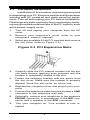
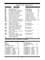
High Performance
V.90/V.34+/V.42bis
56K BPS
PCI Internal
Voice/FAX/Data/
Speakerphone
Modem
User's Manual
Contents
Section One - Introduction .......................... 1
Section Two - Installation ............................. 1
Section Three - AT Command Set ............... 6
Section Four - S Registers ........................ 13
Section Five - Result Codes ...................... 14
Section Six - Troubleshooting .................... 15
Section Seven - Support and Service ......... 17
Appendix A - Specifications ..................... 17
Appendix B - Notices ................................ 17
Part #MAN152 Rev. 1.0
V.90-CL
The information contained in this manual has been
validated at the time of this manual's production.
The manufacturer reserves the right to make any
changes and improvements in the product described in this manual at any time and without
notice. Consequently the manufacturer assumes
no liability for damages incurred directly or indirectly from errors, omissions or discrepancies between the product and the manual.
All registered trademarks are the property of their
respective owners.
Copyright © 1997 All rights reserved. No reproduction
of this document in any form is permitted without prior
written authorization from the Manufacturer.
Section One - Introduction
The MaxTech XPVS56P/C PCI Plug and Play Data,
Fax, Voice Speakerphone Modem connects your computer to all popular high speed modems available today.
The modem utilizes V.90 (56Kbps) technology to provide
increased download speeds using regular telephone
lines. The modem incorporates Plug and Play for ease of
installation.
This manual describes the hardware installation
procedures for your new modem. Additional information
on AT commands and S-registers is provided so that your
system can be customized for a particular operating
environment.
*Note: V.90 is capable of downloading at 56Kbps. However, current FCC regulations limit its speeds to 53Kbps.
Section Two - Installation
This section will provide step by step instructions
on how to install your new 56 Kbps Data, Fax, Voice,
Speakerphone modem. Installation of this modem is a twostep process consisting of: 1) hardware installation and
2) communication software installation.
2.1
Unpacking Your Modem
Be certain that you have all the items listed below.
This package contains:
• A modem
• A telephone cable
• User's manual
• Software for the modem
• Software user's manual
2.2
What You Need
You will need:
1. A phillips-head screw driver.
2. A computer running Microsoft Windows 95 or
later.
3. An available PCI slot in your PC.
Proceed to Section 2.3 now if you have everything required.
1
2.3
Hardware Installation
Installation of this modem requires opening and
manipulating your PC. Exercise caution at all times when
working with AC powered and static-sensitive equipment. Turn off and unplug your PC before installation.
Discharge any static electricity from your body by touching any grounded metal surface of the PC system, such
as its power supply cover.
1.
Turn off and unplug your computer from the AC
outlet.
2.
Remove your computer's cover (refer to your
computer's owner's manual).
3.
Select any available 32-bit PCI card slot and remove
the slot cover (refer to Figure 2-3).
Figure 2-3 PCI Expansion Slots
4.
Carefully slide the PCI internal modem into the slot
you have chosen, applying even pressure until the
modem is completely seated in the slot.
5.
Fasten the retaining bracket with the screw from
the slot cover. Make sure the modem is properly
aligned. Store the slot cover for future use.
6.
Replace the computer cover and plug in your computer.
7.
Connect the telephone cable from the modem's LINE
connector to the telephone wall jack.
8.
Optionally, connect your telephone to the modem's
PHONE connector, a microphone to the MIC connector and a speaker to the SPK connector.
9.
Turn your computer on. Your modem is now installed.
2
2.4
Hardware Configuration
The version of Windows 9x you have will determine
which set of dialog boxes is presented to you when
installing the modem in Windows 9x. Proceed to one of the
following sections, depending on your Windows 9x's
diaglog box:
• Section 2.4.1 when Windows 95 starts for
the first time after card installation, it detects
the modem and it displays the New Hardware Found dialog box
• Section 2.4.1.1 when Windows 95 starts for
the first time after card installation, it detects
the modem and it displays the Update Device
Driver Wizard.
• Section 2.4.1.2 When Windows 98 starts for
the first time after card installation, it detects
the adapter and displays the Add New
Hardware Wizard.
2.4.1 Windows 95 Release 4.00.950
When Windows 95 starts for the first time after card
installation, it detects the modem and displays the New
Hardware Found dialog box.
Under New Hardware Found, when asked to
“Select which driver you want to install for your new
hardware,” click on “Driver from disk provided by hardware manufacturer.” Click “OK.”
The Install From Disk dialog box now instructs
you to “Insert the manufacturer's installation disk into the
drive selected, and then click OK.” Insert the modem's
driver diskette into the disk drive and type A:\ (or B:\ if
inserted in drive B) in the “Copy manufacturer's files
from:” box. Click “OK.”
Windows 95 may request its own installation disks
or CD-ROM for some files. Insert the Windows 95 disks
or CD-ROM as required. When all necessary files are
copied, the modem is configured. Windows 95 will assign
the modem a COM port and IRQ line. Proceed to Section
2.5.
3
2.4.1.1
Windows 95 Release 4.00.950 B
When Windows 95 starts for the first time after card
installation, it detects the modem and displays the Update
Device Driver Wizard. Insert the driver disk into the disk
drive and click “Next.” Windows will find the driver on the
driver disk. Click “Finish. Windows 95 may request its own
installation disks or CD for some files. Insert the Windows
95 disks or CD as required.
Windows will now find a second device on the
modem. Make sure that the driver disk is still in the disk
drive and click “Next.” Windows will find the second
driver. Click “Finish” to complete the installation.
When all necessary files are copied, the modem is
configured. Windows 95 will assign the modem a COM
port and IRQ line. Proceed to Section 2.5.
2.4.1.2
Windows 98
When Windows 98 starts for the first time after card
installation, it detects the adapter and displays the Add
New Hardware Wizard.
Insert the disk that contains your modem drivers into
the appropriate drive and click “Next. Windows 98 will ask
you "What do you want Windows to do" Select "Search
for the best driver for your device". Click "Next". Windows
98 will find the driver on the driver disk. Click "Next".
Windows will now find a second device on the modem.
Make sure that the driver disk is still in the disk drive and
click “Next.” Windows will find the second driver. Click
“Finish” to complete the installation.
When all necessary files are copied, the modem is
configured. Windows 98 will assign the modem a COM
port and IRQ line. Proceed to Section 2.5.
2.5
Software Installation and Configuration
You are now ready to install and configure the
communication software. Refer to your software manual
for installation procedures.
We suggest the following communication parameters when you first use your data communication
4
software. Consult the software manual for information on
using these and other parameters/features.
115,200 bps; 8 data bits; no parity; 1 stop bit;
RTS/CTS flow control set to “on;” initialization
string: AT&F
Select a “Generic Class 1” modem type in your fax
software
Note that your software must be configured to
communicate with the modem on the same COM port and
IRQ line used by the modem.
2.6
Testing Your Modem After Installation
In order to test your modem you should be familiar
with your communication software. Load and set up your
communication software and enter into “terminal mode.”
Make sure that the COM Port and IRQ settings of the
modem match the software. Type AT on your terminal
screen and press ENTER. You may see “AT”, “AATT” or
nothing on the screen. In all cases, the modem should
respond with an OK or 0. If it does not, either the modem
has not been installed properly or the software has not
been properly configured. Review Sections 2.2 -2.5 and
be certain that the modem and the software have been
properly installed. If required, refer to Section 6 for
additional troubleshooting information.
2.7
Using Your Modem
The software included with your modem product
provides a user friendly interface to access the fax, data
and voice/speakerphone functions of your modem. This
software should be sufficient for all of your communication needs. There may be times when you need
to access the modem manually via modem commands.
Read Section 3 for a summary description of the modem
command set before manually accessing the modem. You
may want to read the software manual first, however, as
the software may already provide a user friendly method
of accessing the functions you need (i.e. dialing or
answering calls).
5
2.8
Where To Go From Here
You should familiarize yourself with the functions
available from the included software by reading its
manual. You will be accessing most, if not all, of the
modem's functions from this software. You may also use
any other commercially available communication software with the modem. Read Section 3 only if you are
interested in accessing the modem manually, and not
through the included software. Section 4 and 5 contain
reference material, and can be skipped. If you have
difficulties getting your modem to work, read Section 6
Troubleshooting, to find answers to commonly asked
questions and problems.
Section Three - AT Command Set
3.1
Executing Commands
Commands are accepted by the modem while it is in
Command Mode. Your modem is automatically in Command
Mode until you dial a number and establish a connection.
Commands may be sent to your modem from a PC running
communication software or any other terminal devices.
Your modem is capable of data communication at rates
of: 300,1200,2400,4800,9600,14400,19200,28800,38400,
57600 and 115200 bps. Make sure your COM port baud rate
settings in your communications software is set to one of the
above speeds.
3.2
Command Structure
All commands sent to the modem must begin with
AT and end with ENTER. All commands may be typed in
either upper or lower case, but not mixed. To make the
command line more readable, spaces may be inserted
between commands. If you omit a parameter from a
command that requires one, it is just like specifying a
parameter of 0.
Example:
ATH [ENTER]
This command causes your modem to hang up.
6
3.3
Basic AT Commands
In the following listings, all default settings are
printed in bold text.
Command Function
A
Manually answer incoming call
A/
Repeat last command executed. Do not
precede A/ with AT or follow with ENTER
AT
Appears at the beginning of every
command line
B_
B0
B1
B2
B3
CCITT mode
Bell mode
V.23 at 1200/75
V.23 at 75/1200
C_
C0
C1
Carrier always off
Normal transmit carrier
P
R
T
W
,
@
!
;
0 - 9, A-D, # and *
pulse dialing
originate calls in answer mode
touch-tone dialing
wait for second dial tone
pause
wait for five seconds of silence
flash
return to Command Mode after dialing
D_
DS=n
Dial one of the four telephone numbers
(n=0-3) stored in the modem’s nonvolatile memory
E_
E0
E1
Commands are not echoed
Commands are echoed
F_
F0
F1
Enables online echo
Disables online echo
+++
TIES Escape Characters - Switch from
Data Mode to Command Mode
H_
H0
H1
Force modem on-hook (hang up)
Force modem off-hook (make busy)
I_
I0
I1
I2
I3
I4
Display product-identification code
Factory ROM ID
Internal memory test
Device ID
Reserved
7
I5
I6
I7
I8
I10
Modem chip hardware configuration
Country code
Board manufacturer firmware version
Modem firmware version
Modem board configuration
L_
L0
L1
L2
L3
Low speaker volume
Low speaker volume
Medium speaker volume
High speaker volume
M_
M0
M1
Internal speaker off
Internal speaker on until carrier
detected
Internal speaker always on
Internal speaker on until carrier detected
and off while dialing
M2
M3
N_
N0
N1
Connect only at DTE rate
Automatic rate negotiation
O_
O0
O1
Return to Data Mode
Return to Data Mode and initiate an
equalizer retrain
O3
Renegotiates rate and then returns to
data mode
Set Pulse dial as default
Q0
Q1
Modem sends responses
Modem does not send responses
P
Q_
Sn?
n=0-33 Read and display value in register n
Sn=x
Set register n (n=0-33; x=0-255)
T
Set Tone Dial as default
V_
V0
V1
Numeric responses
Word responses
W_
W0
Modem reports DTE response
codes
Modem reports DTE response codes
Modem reports DCE response codes
Modem reports DTE speed, modulation
mode, error control, data compression,
DCE transmit and receive speed
W1
W2
W3
X_
W4
Modem reports protocol,
compression and DTE data rate
X0
Hayes Smartmodem 300 compatible
responses/blind dialing
8
data
X1
X2
X3
X4
Y_
Y0
Y1
Z_
Z0
Z1
3.4
Same as X0 plus all CONNECT responses/
blind dialing
Same as X1 plus dial tone detection
Same as X1 plus busy signal detection/
blind dialing
All responses and dial tone and
busy signal detection
Modem does not send or respond
to break signals
Modem sends break signal for four
seconds before disconnecting
Reset
and
retrieve
active
configuration profile 0
Reset and retrieve active configuration
profile 1
Extended AT Commands
&C_
&C0 Force Carrier Detect Signal High (ON)
&C1 Turn on Carrier Detect signal when
remote carrier signal is present
&D_
&D0 Modem ignores the Data Terminal Ready
signal
&D1 Modem returns to Command Mode after
DTR toggle
&D2 Modem hangs up, returns to the
Command Mode after DTR toggle
&D3 Resets modem after DTR toggle
&F
&F
&G_
&G0 Guard tone disabled
&G1 550 Hz guard tone
&G2 1800 Hz guard tone
&J_
&J0 Auxiliary relay never operated
&J1 Activates auxiliary relay when modem is
off-hook
&K_
&K0 Disable flow control
&K3 Enable hardware flow control
&K4 Enable software flow control
&M_
&P_
&M0 Asynchronous operation
&P0 United States setting for off-hook(make) to-on-hook (break) ratio
&P1 UK and Hong Kong off-hook-(make) toon-hook (break) ratio
Recall factory default configuration
9
&Q_
&Q0 Modem in asynchronous mode
&S_
&S0 Force DSR Signal High (ON)
&S1 DSR is off in command mode, on in on-line
mode
&T_
&T0 Ends test in progress
&T1 Perform Local Analog Loopback Test
&U_
&U0 Enable Trellis Coding @ V.32
&U1 Disable Trellis Coding @ V.32
&V_
&V0 Displays Active and Stored Profile 0
&V1 Displays Active and Stored Profile 1
&V3 Displays relay and general-purpose I/O
status
&W_
&W0 Stores the active profile as Configuration
Profile 0
&W1 Stores the active profile as Configuration
Profile 1
&Y_
&Y0 Configuration Profile 0 active upon
Power on or reset
&Y1 Configuration Profile 1 active upon Power
on or reset
&Zn=x
n=0-3 Store telephone number x into non-volatile
RAM
+MS?
Displays the current Select Modulation
settings
+MS=?
Displays a list of supported Select
Modulation options
+MS=a,b,c,d
Select modulation where: a=V21, V22,
V22B, V23C, V32, V.32B, V34, V.34S,
V34B, V34BS, V90; b=0-1; c=0-33600;
and d=0-33600. A, b, c, d default=V90,
1, 300, 0. Parameter “a” specifies the
modulation protocol desired. Parameter
“b” specifies automode operations
where: 0=automode disabled, 1=
automode enabled. Parameter “c”
specifies the minimum connection data
rate (0-56600). Parameter “d” specifies
the maximum connection rate (0-56600),
where a 0 specifies highest possible
data rate, depending on the current DTE
rate.
%E_
%E0 V.22bis auto-retrain disabled
10
%E1 V.22bis auto-retrain enabled
%E2 Enable line signal quality monitor and
fallback/fallforward
%G_
%G0 Enable Auto Fall Forward/Back
%G1 Disable Auto Fall Forward/Back
-C_
-C0
-C1
-C2
3.5
Calling tone disabled
1300hz calling tone
V.8 and 1300hz calling tones enabled
MNP/V.42/V.42bis Commands
%An
Set auto-reliable fallback character to n
(where n = 0 to 127, ASCII). Requires the
\C2 setting. Default=13
%C_
%C0 Disable MNP Class 5 data compression
%C1 Enable MNP Class 5 data
compression
\A_
\A0
\A1
\A2
\A3
\Bn
\C_
64-character maximum MNP block size
128-character maximum MNP block size
192-character maximum MNP block size
256-character maximum MNP block
size
Send a 1/10 second line break to the
modem, where n = 1 to 9. At normal
connect, the default is 0
\C0
\C1
\C2
Do not buffer data during LAPM/
MNP handshaking
Buffer all data for 4 seconds, until
receiving 200 characters or until a packet
is detected
Do not buffer data; switch to normal
mode when fallback character is
detected
\G_
\G0
\G1
Disable DCE flow control
Enable DCE flow control
\J_
\J0
Disable serial port data rate
adjustment (keep high data rate
between
DTE
and
modem,
regardless of modem-to-modem
data rate)
Enable serial port data rate adjustment
so serial data rate automatically adjusts
to match the modem-to-modem data rate
\J1
\Kn
Set break control, where n= 0 to 5.
11
Default is 5
\N_
\N0
\N1
\N2
\N3
\N4
Normal data-link only
Normal data-link only
MNP data link only
V.42/MNP/Normal data link
V.42 data link only
\Q0
\Q1
\Q2
Turn off flow control
XON/XOFF software flow control
CTS signal unidirectional hardware flow
control
RTS/CTS signal bi-directional
hardware flow control
\O
Initiate reliable link during a normal link
\Q_
\Q3
\T n
Inactivity timer, where n = 0 to 90 minutes.
Default is 0
\U
Accept reliable link during a normal link
\X_
\X0
\X1
Process XON/XOFF but don’t pass
through
Process XON/XOFF and pass through
\Y
Switch to reliable link from normal link
\Z
End the reliable connection and switch to
normal operation
-J
-J0
-J1
Disable error control detection phase
Enable error control detection
phase
"H
"H0
"H1
V.42bis data compression disabled
Can send but not receive V.42bis data
compression
Can receive but not send V.42bis data
compression
Bidirectional
V.42bis
data
compression enabled
"H2
"H3
"On
3.6
Set maximum V.42bis data block size to
n (n=6-250). Default is 32
Fax Class 1 Commands
+FAE=n
+FCLASS=1
+FRH=n
+FRM=n
+FRS=n
Data/Fax auto answer enable. Default is
0
Sets FAX operating mode
Receive HDLC data
Receive data
Wait for silence
12
+FTH=n
+FTM=n
+FTS=n
3.7
Transmit HDLC data
Transmit data
Stop transmission and pause
ISO 101 Voice Mode Commands
+FCLASS=8
+FLO
+VBT=n
+VCID=n
+VCSD=n
+VDR=n
+VEM=n
+VGM=n
+VGR=n
+VGS=n
+VGT=n
+VIP
+VIT=n
+VLS=n
+VNH=n
+VRA=n
+VRN=n
+VRX
+VSD=n
+VSM=n
+VSP=n
+VTD=n
+VTS=n
+VTX
Voice modem select
Flow control select
Buffwe threshold setting
Caller ID selection
Voice command mode silence detection
Distinctive ring selection
Event reporting and masking
Speakerphone microphone gain
Receive gain selection
Speakerphone speaker gain
Volume selection
Initialize parameter
DTE/DCE inactivity timer
Relay/speaker control
Automatic hang-up control
Ringback-goes-away timer
Ringback-never-appeared timer
Record mode
Silence detection (quiet and silence)
Compression method selection
Speakerphone on/off control
Beep tone duration timer
DTMF and tone generation
Play mode
Section Four - S Registers
Your modem has 24 registers, designated S0
through S33. Table 4-1 shows the registers, their functions, and their default values. Some registers can have
their values changed by commands. If you use a command to change a register value, the command remains
in effect until you turn off or reset your modem. Your
modem then reverts to the operating characteristics
specified in its non-volatile memory. Refer to Section 3 for
information on how to use the AT commands to manipulate
the S registers.
13
Table 4-1 S - Registers
Register
S0
S1
S2
S3
S4
S5
S6
S7
S8
S9
S10
S11
S12
S14
S16
S18
S21
S22
S23
S25
S27
S30
S31
S33
Function
Range/units Default
Auto-answer Ring
Ring counter
Escape code character
Carriage return character
Line feed character
Backspace character
Dial tone wait time
Remote carrier wait time
Comma pause time
Carrier detect time
Carrier loss time
Touch-tone dialing speed
Esc. character detect time
Echo, response, dialing,
originate/answer
Modem test options
Modem test timer
DTR, DCD, DSR, and
Long Space Disconnect
Speaker and response
RDL, DTE data rate,
parity,and guard tone
DTR delay
Async operation, CCITT/
Bell mode
Disconnect timer
Automode,Trellis coding,
calling tone, auto-retrain,
rate renegotiation
Sleep mode time
0-255/rings
0-255/rings
0-127/ASCII
0-127/ASCII
0-127/ASCII
0-32, 127/ASCII
0-255/seconds
1-255/seconds
0-255/seconds
0-255/0.1 second
0-255/0.1 second
50-255/0.001 second
0-255/0.02 second
Bit-mapped
Bit-mapped
0-255/seconds
Bit-mapped
0
0
43
13
10
8
2
60
2
6
7
70
50
0
Bit-mapped
Bit-mapped
0-100/seconds
Bit-mapped
5
0-255/seconds
Bit-mapped
0
0-90/seconds
10
Section Five - Result Codes
BASIC RESPONSE CODES
OK
RING
ERROR
NO DIALTONE
NO ANSWER
CONNECT 75/1200
CONNECT 4800
CONNECT 9600
CONNECT 14400
CONNECT 19200
CONNECT 24000
CONNECT 28800
0
2
4
6
8
23
11
12
13
14
62
64
CONNECT
NO CARRIER
CONNECT 1200
BUSY
CONNECT 1200/75
CONNECT 2400
CONNECT 7200
CONNECT 12000
CONNECT 16800
CONNECT 21600
CONNECT 26400
CONNECT 31200
14
1
3
5
7
22
10
24
25
59
61
63
65
CONNECT 33600
CONNECT 38400
CONNECT 42666
CONNECT 45333
CONNECT 48000
CONNECT 50666
CONNECT 53333
CONNECT 56000
CONNECT 57600
DATA
RINGBACK
66
28
36
38
42
53
55
57
18
35
45
CONNECT
CONNECT
CONNECT
CONNECT
CONNECT
CONNECT
CONNECT
CONNECT
CONNECT
FAX
37333
41333
44000
46666
49333
52000
54666
57333
115200
34
35
37
39
43
54
56
58
31
33
Section Six - Troubleshooting
This section describes some of the common problems you may encounter while using your modem. If you
can not resolve your difficulty after reading this chapter,
contact your dealer or vendor for assistance.
Modem does not respond to commands.
1. Make sure the modem is not configured with a
conflicting COM port and IRQ setting (see Sections
2.2-2.5). As an example, your modem can not be
configured as COM1 if another device in your system
is also configured as COM1.
2. Make sure the communication software is configured
to “talk” to the modem on the correct COM port and IRQ
setting (same COM port and IRQ setting as the
modem). Your communication software must know
which address your modem is using in the system in
order to pass data to it. Similarly, IRQ settings must be
set correctly to receive data from the modem.
3. Make sure that your modem is initialized correctly.
Your modem may have been initialized to not display
responses. You may factory-reset the modem by
issuing AT&F and pressing ENTER. The factory
default allows the modem to display responses after
a command has been executed.
4. Make sure the baud rate setting in your software is
set to 115200, 57600, 38400, 19200, 14400, 9600,
2400, 1200, or 300 bps. An incorrect baud rate
prevents the modem from operating properly.
15
Modem does not dial.
1. Make sure the modem is connected to a working
phone line. Replace the modem with a working phone
to ensure that the phone line is working.
Modem dials but does not connect.
1. Make sure the IRQ setting is identical on both the
modem AND the software. Modem and software
must be configured identically.
2. Make sure the phone line is working properly. Replace
the modem with a regular phone and dial the number.
If the line sounds noisy, you may have difficulty
connecting to the remote device.
Modem makes a connection but no data
appears on your screen.
1. The remote system may be waiting to receive your
data before it begins. Try pressing the ENTER key a
few times.
2. Make sure the correct data format (data bits, stop bits,
and parity bits) and flow control (RTS/CTS) are being
used.
3. Make sure the correct terminal emulation mode is
being used.
High pitch tone is heard whenever you answer
the phone.
1. Make sure Auto-Answer is turned off. Your modem
is factory configured to NOT auto-answer. Issue
AT&F to factory reset your modem.
Modem experiences errors while
communicating with a remote modem.
1. Make sure the DTE speed is the same as the modem
connection speed when in Direct Mode.
2. Make sure the remote system and your modem use the
same communication parameters (speed, parity, etc.).
3. Make sure RTS/CTS hardware flow control is enabled
and XON/XOFF software flow control is disabled in
the communication software.
16
Modem experiences bursts of errors or
suddenly disconnects while communicating
with a remote modem.
1. Make sure Call Waiting is turned off.
2. Make sure the phone line does not exhibit excess
noise.
Section Seven - Support and Service
In the unlikely event you experience difficulty in the
use of this product, we suggest you: (1) consult the
Troubleshooting section of this guide and (2) consult with
your dealer. To obtain service for this product, follow the
Return Merchandise Authorization Procedure as outlined
in the Warranty card.
Appendix A - Specifications
Communication Std. V.90, x2, V.34+ , V.34, V.32bis, V.32, V.29,
V.27ter, V.22bis, V.23, V.22, V.21, V.17,
Bell212/103
Data Compression: V.42bis/MNP5
Error Correction:
V.42/MNP2-4
Host Interface:
PCI
FAX Group:
Group III Send/Receive Standard
FAX Command set: EIA/TIA-578 Service Class 1
Speakerphone:
Full-Duplex
Transmit level:
-10dBm
Receiver sensitivity: -36dBm
UART:
16550 compatible
Data format:
300-115200 bps (8N1, 7E1, 7E2, 7O1, 7O2)
Power:
0.75 W
Temperature:
0-55 degrees C (operating); -20 to 80 degrees C (non-operating)
Appendix B - Notices
FCC Compliance
This equipment complies with Part 68 of the FCC Rules. On this
equipment is a label that contains, among other information, the
FCC registration number and Ringer Equivalence Number (REN)
for this equipment. You must, upon request, provide this information to your telephone company.
If your telephone equipment causes harm to the telephone
network, the Telephone Company may discontinue your service
temporarily. If possible, they will notify in advance. But, if
advance notice isn’t practical, you will be notified as soon as
possible. You will be informed of your right to file a complaint with
17
the FCC.
Your telephone company may make changes in its facilities,
equipment, operations, or procedures that could affect proper
operation of your equipment. If they do, you will be notified in
advance to give you an opportunity to maintain uninterrupted
telephone service.
The FCC prohibits this equipment to be connected to party lines
or coin-telephone service.
In the event that this equipment should fail to operate properly,
disconnect the equipment from the phone line to determine if it is
causing the problem. If the problem is with the equipment,
discontinue use and contact your dealer or vendor.
The FCC also requires the transmitter of a FAX transmission be
properly identified (per FCC Rules Part 68, Sec. 68.381 (c) (3)).
FCC Class B Statement
This equipment has been tested and found to comply with the limits
for a Class B digital device, pursuant to Part 15 of the FCC Rules.
These limits are designed to provide reasonable protection against
harmful interference in a residential installation. This equipment
generates, uses and can radiate radio frequency energy, and if not
installed and used in accordance with the instructions, may cause
harmful interference to radio communications. However, there is
no guarantee that interference will not occur in a particular
installation. If this equipment does cause harmful interference to
radio or television reception, which can be determined by turning the
equipment off and on, the user is encouraged to try to correct the
interference by one or more of the following measures:
• Reorient or relocate the receiving antenna
• Increase the separation between the equipment and the receiver
• Connect the equipment into an outlet on a circuit different from
that to which the receiver is connected
• Consult the dealer or an experienced radio / TV technician for
help
Notice: 1) Shielded cables, if any, must be used in order to comply
with the emission limits. 2) Any change or modification not
expressly approved by the Grantee of the equipment authorization
could void the user’s authority to operate the equipment.
DOC Compliance Information
NOTICE: The Canadian Department of Communications label
identifies certified equipment. This certification means that the
equipment meets certain telecommunications network protective,
operational and safety requirements. The Department does not
guarantee the equipment will operate to the user’s satisfaction.
18
Before installing this equipment, users ensure that it is permissible
to be connected to the facilities of the local telecommunications
company. The equipment must also be installed using an acceptable method of connection. The customer should be aware that
compliance with the above conditions may not prevent degradation
of service in some situations.
Repairs to certified equipment should be made by an authorized
Canadian maintenance facility designated by the supplier. Any
repairs or alterations made by the user to this equipment, or
equipment malfunctions, may give the telecommunications company cause to request the user to disconnect the equipment.
Users should ensure for their own protection that the electrical
ground connections of the power utility, telephone lines and internal
metallic water pipe system, if present, are connected together. This
precaution may be particularly important in rural areas.
Caution: Users should not attempt to make such connections
themselves, but should contact the appropriate electric inspection
authority, or electrician, as appropriate.
NOTICE: The Load Number (LN) assigned to each terminal device
denotes the percentage of the total load to be connected to a
telephone loop which is used by the device, to prevent overloading.
The termination on a loop may consist of any combination of
devices subject only to the requirement that the sum of the Load
Numbers of all the devices does not exceed 100.
UL Notice
Caution: This internal modem adapter is to be installed in UL Listed
computers only. Always disconnect the modem adapter from the
telephone system during installation or when the covers are
removed from the computer.
Man152 First Edition
GZ/DR/DGR - Version 1.0
19