1
ORDER NO.
CPD0706228C1
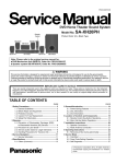
Notebook Computer
Model No.
CF-52AJYZDZM
This is the Service Manual for
the following areas.
M …for U.S.A. and Canada
© 2007 Matsushita Electric Industrial Co., Ltd. All rights reserved.
Unauthorized copying and distribution is a violation of law.
1
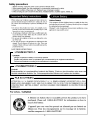
LASER SAFETY INFORMA TION
For U.S.A.
Class 1 LASER-Product
This product is certified to comply with DHHS Rules 21 CFR Subchapter J.
This product complies with European Standard EN60825 (or IEC Publication 825)
For all areas
This equipment is classified as a class 1 level LASER product and there is no hazardous LASER radiation.
Caution:
(1) Use of controls or adjustments or performance of procedures other than those specified herein may result in
hazardous radiation exposure.
(2) The drive is designed to be incorporated into a computer-based system or unit which has an enclosing cover.
It should never be used as a stand alone drive.
Danger:
The serviceman should not remove the cover of drive unit and should not service because the drive unit is a nonserviceable part.
Please check DANGER label on PD-drive unit.
• Unplug the AC power cord to the equipment before opening the top cover of the drive.
• When the power switch it on, do not place your eyes close to the front panel door to look into the interior of the unit.
LASER Specification
Class 1 level LASER Product
Wave Length: DVD 658±8 nm
CD 775~815 nm
Laser safety information is appropriate only when drive with laser is installed.
2
3
4
CONTENTS
1. Specifications ··················································································································1-1
2. Names and Functions of Parts ······················································································2-1
3. Block Diagram ···············································································································3-1
4. Diagnosis Procedure ·····································································································4-1
5. Power-On Self Test (Boot Check) ·················································································5-1
6. List of Error Codes <Only when the port replicator is connected> ································6-1
7. Self Diagnosis Test ········································································································7-1
8. Wiring Connection Diagram ··························································································8-1
9. Disassembly/Reassembly ·····························································································9-1
10. Exploded View ···········································································································10-1
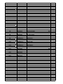
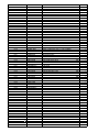
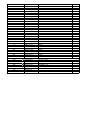
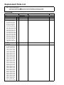
11. Replacement Parts List ·····························································································11-1
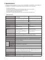
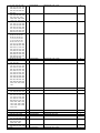
1. Specifications
This page provides the specifications for the basic model CF-52AJCBDBM / CF-52BJCBZBM / CF-52AJCHDBM / CF52CCABXBM / CF-52DCABZBM. The model number is different according to the unit configuration.
To check the model number:
Check the bottom of the computer or the box the computer came in at the time of purchase.
To check CPU speed, memory size and the hard disk drive (HDD) size:
Run the Setup Utility and select [Information] menu.
[CPU Speed]: CPU speed, [System Memory]: Memory size, [Hard Disk]: Hard disk drive size
Main Specifications
Model No.
CF-52AJCBDBM / CF-52BJCBZBM /
CF-52AJCHDBM
CF-52CCABXBM / CF-52DCABZBM
CPU
Intel® Core™ 2 Duo Processor T7300
(2.0 GHz, 4 MB*1 L2 cache, 800 MHz FSB)
Intel® Core™ 2 Duo Processor T7100
(1.8 GHz, 2 MB*1 L2 cache, 800 MHz FSB)
Chipset
Mobile Intel® PM965 Express Chipsets
Mobile Intel® GM965 Express Chipsets
Memory*1*2
1024 MB (4096 MB Max.)
Video Memory*1
512 MB
UMA (384 MB Max.)*3
Hard Disk Drive*4
120 GB
80 GB
Display Method
15.4 WUXGA type (TFT)
15.4 WXGA type (TFT)
Internal LCD*5
65,536/16,777,216 colors
(800 × 600 dots/1024 × 768 dots/1280 × 768
dots/1600 × 1200 dots/1920 × 1080 dots/
1920 × 1200 dots)
65,536/16,777,216 colors
(800 × 600 dots/1024 × 768 dots/1280 × 768
dots/1280 × 800 dots)
External Display*6
65,536/16,777,216 colors (800 × 600 dots/1024 × 768 dots/1280 × 768 dots/1280 × 1024 dots/
1600 × 1200 dots/1920 × 1080 dots/1920 × 1200 dots/2048 × 1536 dots)
LAN
IEEE 802.3 10Base-T, IEEE 802.3u 100Base-TX, IEEE 802.3ab 1000Base-T
Modem
Data: 56 kbps (V.92) FAX: 14.4 kbps
Sound
WAVE and MIDI playback, Stereo speaker, Intel® High Definition Audio subsystem support
Security Chip
TPM (TCG V1.2 compliant)*9
Card Slot
PC Card
Type I or Type II x 1 (3.3 V: 400 mA, 5 V: 400 mA)
ExpressCard
ExpressCard/34 or ExpressCard/54 x 1
SD Memory Card*10 x 1, Data transfer rate = 8 MB per second*11
Smart Card*12
x1
RAM Module Slot
200-pin, 1.8 V, SO-DIMM, DDR2 SDRAM, PC2-5300 Compliant
Interface
USB port (4-pin, USB 2.0) x 4, Serial Port (Dsub 9-pin male), Modem port (RJ-11), LAN port
(RJ-45), External display port (Mini Dsub 15-pin female), IEEE1394a Interface Connector (4-pin
× 1), Microphone Jack (Miniature jack, 3.5 DIA, Stereo), Headphone Jack (Miniature jack, 3.5
DIA, Impedance 32 Ω, Output Power 4 mW × 2, Stereo)
Keyboard / Pointing Device
87 keys / Touch Pad
Power Supply
AC adaptor or Battery pack
AC Adaptor*13
Input: 100 V to 240 V AC, 50 Hz/60 Hz, Output: 15.6 V DC, 8.0 A
1-1
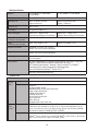
Main Specifications
Model No.
CF-52AJCBDBM / CF-52BJCBZBM /
CF-52AJCHDBM
Battery Pack
Li-ion 11.1 V, 7.65 Ah
Operating Time*14
Approx. 3.5 hours to 4.5 hours*15
(Approx. 4.5 hours*16)
Charging Time*14
Approx. 4 hours
Clock Battery
Coin type lithium battery 3.0 V
Power Consumption*17
Approx. 60 W*18/ Approx. 100 W
(Maximum when recharging in the ON state)
CF-52CCABXBM / CF-52DCABZBM
Approx. 6.0 hours to 9.5 hours*15
(Approx. 7.5 hours*16)
Approx. 45 W*18/ Approx. 100 W
(Maximum when recharging in the ON state)
Physical Dimensions (W × H × D) 355.7 mm × 50.7 - 51.9 mm × 286.8 mm {14.0" × 2.0 " × 11.3"}
(including the carrying handle)
Weight
(including the carrying handle)
Approx. 3.35 kg {Approx. 7.4 lb.}
Approx. 3.3 kg {Approx. 7.3 lb.}
Operation Environment
Temperature: 5 °C to 35 °C {41 °F to 95 °F}
Humidity: 30% to 80% RH (No condensation)
Storage Environment
Temperature: -20 °C to 60 °C {-4 °F to 140 °F}
Humidity: 30% to 90% RH (No condensation)
Operating System
Microsoft® Windows® XP Professional Service Pack 2 with Advanced Security Technologies
(NTFS File System)
Utility Programs
DMI Viewer, Adobe Reader, PC Information Viewer, SD Utility, Icon Enlarger, Loupe Utility,
WinDVD™ 5 (OEM Version), B’s Recorder GOLD8 BASIC, B’s CLiP 6,
Intel® PROSet/Wireless Software*7, Bluetooth™ Stack for Windows® by TOSHIBA*8,
Wireless Switch Utility, Hotkey Settings, Battery Recalibration Utility,
Infineon TPM Professional Package*19, Recover Pro™ 6*19
Setup Utility, Hard Disk Data Erase Utility*20
CD/DVD Drive
CD/DVD Drive
Data
Transfer
Rate*21
DVD MULTI Drive
Reading*22
DVD-ROM: 8X (Max.), CD-ROM: 24X (Max.)
Writing*23
CD-R: 4X/10X/10-16X/10-20X/10-24X
CD-RW: 4X
High-Speed CD-RW: 4X/10X
Ultra-Speed CD-RW: 10X/10-16X/10-20X/10-24X
DVD-R: 1X/2X/2-4X/2-6X/2-8X
DVD-RW: 1X/2X/2-4X/2-6X
DVD-RAM: 2X/3X/3-5X
+R: 2.4X/2.4-4X/2.4-6X/2.4-8X
+R DL: 2.4X/2.4-4X
+RW: 2.4X/2.4-4X
High-Speed +RW: 3.3X/3.3-6X/3.3-8X
Supported Reading
Discs/
Format*4
Writing
DVD-ROM (4.7 GB, 8.5 GB, 9.4 GB, 17 GB), DVD-Video, DVD-R (1.4 GB, 3.95 GB, 4.7 GB),
DVD-R DL (8.5 GB), DVD-RW*24 (1.4 GB, 2.8 GB, 4.7 GB, 9.4 GB), DVD-RAM*25 (1.4 GB,
2.8 GB, 4.7 GB, 9.4 GB), +R (4.7 GB), +R DL (8.5 GB), +RW (4.7 GB), CD-Audio, CD-ROM,
CD-R, Photo CD, Video CD, CD-RW, CD TEXT, CD-EXTRA
DVD-R (1.4 GB, 4.7 GB for General), DVD-R DL (8.5 GB),
DVD-RW*24 (1.4 GB, 2.8 GB, 4.7 GB, 9.4 GB), DVD-RAM*25 (1.4 GB, 2.8 GB, 4.7 GB, 9.4 GB),
+R (4.7 GB), +R DL (8.5 GB), +RW (4.7 GB), CD-R, CD-RW
1-2
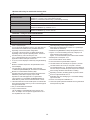
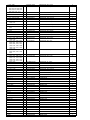
Wireless LAN <Only for model with wireless LAN>
Intel® Wireless WiFi link 4965 AGN (802.11 a + b + g)*26
Data Transfer Rates*27
IEEE802.11a: 54/48/36/24/18/12/9/6 Mbps (automatically switched)
IEEE802.11b: 11/5.5/2/1 Mbps (automatically switched)
IEEE802.11g: 54/48/36/24/18/12/9/6 Mbps (automatically switched)
Standards Supported
IEEE802.11a/IEEE802.11b/IEEE802.11g
Transmission method
OFDM system, DSSS system
Wireless Channels Used
IEEE802.11a: Channels 36/40/44/48/52/56/60/64/149/153/157/161/165
IEEE802.11b/IEEE802.11g: Channels 1 to 11
RF Frequency Band
IEEE802.11a: 5.18-5.32 GHz, 5.745-5.825 GHz
IEEE802.11b/IEEE802.11g: 2.412-2.462 GHz
Bluetooth™ <Only for model with Bluetooth>
Bluetooth Version
2.0 + EDR
Transmission method
FHSS system
Wireless Channels Used
Channels 1 to 79
RF Frequency Band
2.402-2.48 GHz
*1
*2
*3
*4
*5
*6
*9
*10
*11
*12
*13
*14
1MB = 1,048,576 bytes
You can physically expand the memory up to 4096 MB, but
the total amount of usable memory available will be less
depending on the actual system configuration.
A segment of the main memory is allotted automatically
depending on the computer’s operating status. The size of
the Video Memory cannot be set by the user.
1GB = 1,000,000,000 bytes. Your operating system or some
application software will report as fewer GB.
A 16,777,216 color display is achieved by using the dithering
function.
Maximum resolution depends on the specifications of the
external display.
For information on TPM, click [start] - [Run] and input
“c:\util\drivers\tpm\README.pdf”, and refer to the Installation
Manual of “Trusted Platform Module (TPM)”.
Operation has been tested and confirmed using Panasonic
SD Memory Cards with a capacity of up to 2 GB.
Operation on other SD equipment is not guaranteed.
This computer is not compatible with MultiMediaCards or
SDHC Memory Cards. Do not insert these kinds of cards.
Theoretical value and not the actual speed. The transfer rate
does not become higher even if you use a card that supports
the higher transfer rate.
Only for model with Smart Card slot
<Only for North America>
The AC adaptor is compatible with power sources up to
240 V AC adaptor. The computer is supplied with a 125 V
AC compatible AC cord. 20-M-2-1
*15
*16
*17
*18
*19
*20
*21
*22
*23
*24
*25
*26
*27
1-3
Varies depending on the usage conditions.
Measured using BatteryMark™ Version 4.0.1 (LCD brightness: Maximum - Minimum)
Measured using MobileMark™ 2005 (LCD brightness: 60 cd/m2)
Approx. 0.9 W when the battery pack is fully charged (or not
being charged) and the computer is OFF.
Approx. 1.5 W when the Wake up from LAN has been enabled.
Rated power consumption 23-E-1
You need to install to use the feature.
The Product Recovery DVD-ROM is required.
The data transfer rate of DVD per 1X speed is 1,350 KB/s.
The data transfer rate of CD per 1X speed is 150 KB/s.
If an unbalanced disc (e.g., the balance has been displaced
from the center) is inserted, the speed may become slower if
there are large vibrations while the disc is rotating.
Depending on the disc, the writing speed may become slower.
Does not support DVD-RW Ver.1.0.
DVD-RAM: Only non-cartridge type or removable cartridge
type can be used.
It does not correspond to IEEE802.11n.
These are speeds specified in IEEE802.11a+b+g standards.
Actual speeds may differ.
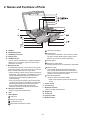
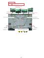
2. Names and Functions of Parts
G
H
I
J
K
A
A
L
M
N
B
I
I
C
O
D
I
E
F
P
A : Speaker
Hard disk drive status
B : Multimedia pocket
Power status
(Off: Power off/Hibernation, Green: Power on, Blinking green: Standby, Blinking green rapidly: Cannot
power on or resume due to low temperature.)
Battery status
C : SD Memory Card slot
D : Battery pack
E : Headphone jack
You can connect headphones or amplified speakers.
When they are connected, audio from the internal
speakers is not heard.
F : Microphone jack
A condenser microphone can be used. If other types
of microphones are used, audio input may not be possible, or malfunctions may occur as a result.
• When recording in stereo using a stereo microphone:
Click [start] - [All Programs] - [SoundMAX] - [Control
Panel] and select [Microphone], and then add a
check mark for [No Filtering] in [Microphone
Enhancements].
• When using a monaural microphone with a 2-terminal plug:
Click [start] - [All Programs] - [SoundMAX] - [Control Panel]
and select [Microphone], and then add a check mark for
[Voice Recording] in [Microphone Enhancements].
Otherwise, only audio on the left track will be recorded.
G : Wireless LAN antenna
<Only for model with wireless LAN>
H : LCD
I : LED indicator
Caps lock
SD Memory Card status
(Blinking: During access or a password is requested)
Wireless ready
This indicator lights when Wireless LAN, Bluetooth, and/or Wireless WAN are connected and
ready. It does not necessarily indicate the On/Off
condition of the wireless connection.
Wireless WAN status
<Only for model with wireless WAN>
Refer to the instruction manual of the wireless
device
J : Power switch
K : Function key
L : Bluetooth antenna
<Only for model with Bluetooth>
M : Keyboard
N : Touch pad
O :Carrying handle
P : Wireless switch
Numeric key (NumLk)
Scroll lock (ScrLk)
Multimedia pocket device status
2-1
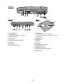
Right side
A B
C
D
G
EX PC
E
F
1394
Rear side
Bottom
N
O
F
H
I
J
K
L
M
Q
R
P
LOCK
A : Hard disk drive
B : Smart Card slot
<Only for model with Smart Card slot>
C : ExpressCard slot
I : Security lock
A Kensington cable can be connected.
For further information, read the manual that comes
with the cable.
J : Ventilation hole
K : Modem port
D :PC Card slot
E : IEEE 1394 interface connector
L : LAN port
F : USB port
M : Serial port
N : Expansion bus connector
O : RAM module slot
G : DC-IN jack
H : External display port
P : Hard disk drive latch
Q : Multimedia pocket release button
R : Battery latch
2-2
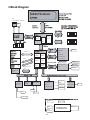
3 Block Diagram
Intel® Core™
Intel
Core Duo 2 processor
Processor Number T7300
L2 Cache 4M
(uFCBGA)
LCD
Clock
ock Sp
Speed
eed 2GHz
Front Side Bus 800MHz
(15.4” WXGA or WUXGA)
CRT
Processor
AGTL+
System Bus
64bit 800 MHz
Main Memory(DDR2-SDRAM )
SO-DIMM 2 (512MB / 1G / 2G)
Max 4G BYTE 667 MHz CL4
533 / 667MHz
VGA (1.15V)
Radeon X????
(M71M) ATi
64bit
PM965 (1.05V)
PCI
Express
PCI
Express
Memory
Host
1.8V
Interface
Hub
Bridge
64bit
DMI x 4
USB2.0 x4
iCH8-M (1.05V)
USB 2.0/1.1
FingerPrint
Bluetooth
WWAN
SATA
HDD
80GB/100GB
2.5inch
COMBO
MULTI
GLAN
I/F
USB x10
PCI
Interface
Express
Secondary IDE
MC82566
PCI
Express
Mini-Card
Wireless LAN
802.11 a+b+g
ExpressCard
LPC
HD Audio
Bridge
Interface
PCI Bus
33MHz
LPC Bus 3.3V
TPM 1.2
SLB9635
Infineon
Super I/O
PC87391
Winbond
TYPE I
Card Bus(3.3V)
SD SLOT
Ricoh
IEEE1394
SPI
BIOS ROM
AT26DF321
Atmel
RJ-45
Intel
SATA/IDE PCI
Interface
Bridge
or
Gig bit Ethernet
Intel® High Definition Audio Interface
Intel
EC
Mitsubishi
Audio(3.3V)
AD1884
Analog Devices
Microphone
(EXT)
Headphone
Modem(3.3V)
RD02-D330
Conexant
Speaker
Int KB
Serial
Flat Pad
Smart Card
Serial
CRT
LAN
1000BASE
3-1
Power SW
Port Re
Port
Replicato
plicator Conn
Conn
USB 2.0 x4
RJ-11
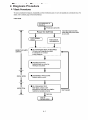
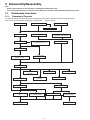
4 Diagnosis Procedure
4.1.
4-1
4.2.
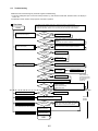
Troubleshooting
Please take note of the following two points with regard to troubleshooting:
1. Know-how of diagnosis upon occurrence of heavy troubles, e.g. ‘Set cannot be turned ON’, ‘Set fails to start’, ‘No display on
screen’, etc.
2. Explanation of each trouble, mainly symptom of trouble in operation.
● Flow Chart
START
START
Set cannot be supplied with current.
Power lamp fails to light up.
Pay attention to the following points when in pursuit of the cause of a troubleshooting.
1. Peripheral apparatus connected with the set should all be removed before operation check.
2. Make sure that cables, boards, etc. are not coming off, and recheck the contact condition.
NG
AC
Adaptor/Battery
Output voltage
Replace AC Adaptor/Battery
OK
NO
Power lamp
check
YES
Dark display on screen.
Screen fails to display.
NG
Inverter board
Check contact condition of power input terminal. Replace if
defective.
Check Power SW. Replace if defective.
Replace inverter board.
Check inverter cable continuity. Replace if defective
OK
NO
LCD back
light lighting
YES
NG
LCD unit
check
Replace LCD back light.
Replace LCD unit.
OK
Failure in starting
NO
BIOS operation
check
Replace main board (Check fuse at power source).
YES
NG
Result of
POST
OK
NG
Set-up utility
starting
Refer to POST
error code table.
Replace main board.
Replace main board.
OK
Return set-up utility setpoint to the state of ‘delivery from factory’.
NO
HDD access
YES
Not displayed properly on screen.
NG
Main board
check
Heavy trouble e.g.,
‘Set cannot be turned
ON’, ‘Set fails to start’,
‘No display on
screen’, etc.
Check HDD cable connection and continuity.
Replace if defective.
Replace HDD & Reinstall.
Replace main board.
Replace main board
OK
Some or all keys cannot be input.
DVD/CD CALL not practicable.
Make sure of contact of K/B connector in use.
Replace keyboard or main board.
NO
Trouble
symptoms on some
of DVD or CD
YES
*Clean DVD-ROM drive with an applicator.
Replace DVD drive.
Replace main board.
Starts but operates unstably.
Reinstall HDD.
Replace main board.
START
END
4-2
Check if there are any flaws on DVD or CD
media. Since flaws may appear on specific
media, DVD or CD media can be defective.
Each kind of
trouble in
operation.
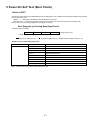
5 Power-On Self Test (Boot Check)
Outline of POST
The set has a boot check function called POST (Power-On Self Test) in it. The condition of the main body is diagnosed by checking
beep sound or error code.
z Start .............Test begins automatically when power switch is set to ON.
z Normal finish .....After memory checking, a beep sound is issued once and the set is placed into automatic stop.
Note: If no error occurs, nothing is displayed. (No display of OK, etc.)
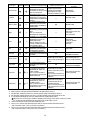
Error Diagnosis by Checking Beep Signal Sound
The beep sound is as follows:
(1 (long sound) -2-3-4)
(Length of bar shows length of sound.)
= long sound (about 0.4 sec.),
= short sound (about 0.2 sec.), Length between sounds is about 0.1 sec.
z Table of errors classified by beep sounds
Diagnosis
Main board
Beep signal sound
Error message
1(long sound)-2
BIOS ROM error
1-2-2-3
BIOS ROM error
1-3-1-1
RAM error
1-3-1-3
Keyboard controller error
1-3-4-1
RAM error
1-3-4-3
RAM error
1-4-1-1
RAM error
2-1-2-3
BIOS ROM error
2-2-3-1
Occurrence of unexpected offering
(Note) A beep sound is also issued in case of other I/O trouble.
5-1
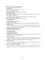
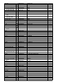
6 List of Error Codes <Only when the port replicator is connected>
The following is a list of the messages that BIOS can display. Most of them occur during
POST. Some of them display information about a hardware device, e.g., the amount of memory
installed. Others may indicate a problem with a device, such as the way it has been configured.
Following the list are explanations of the messages and remedies for reported problems.
If your system displays one of except the messages marked below with an asterisk (*), write
down the message and contact Panasonic Technical Support. If your system fails after you
make changes in the Setup menus, reset the computer, enter Setup and install Setup defaults
or correct the error.
0200 Failure Fixed Disk
Fixed disk in not working or not configured properly. Check to see if fixed disk is attached
properly. Run Setup. Find out if the fixed-disk type is correctly identified.
0210 Stuck key
Stuck key on keyboard.
0211 Keyboard error
Keyboard not working.
0212 Keyboard Controller Failed
Keyboard controller failed test. May require replacing keyboard controller.
0213 Keyboard locked - Unlock key switch
Unlock the system to proceed.
0230 System RAM Failed at offset : nnnn
System RAM failed at offset nnnn of in the 64k block at which the error was detected.
0231 Shadow RAM Failed at offset : nnnn
Shadow RAM failed at offset nnnn of the 64k block at which the error was detected.
0232 Extended RAM Failed at offset : nnnn
Extended memory not working or not configured properly at offset nnnn.
0250 System battery is dead - Replace and run SETUP
The CMOS clock battery indicator shows the battery is dead. Replace the battery and run Setup
to reconfigure the system.
*0251 System CMOS checksum bad - Default configuration used
System CMOS has been corrupted or modified incorrectly, perhaps by an application program
that changes data stored in CMOS. The BIOS installed Default SETUP Values. If you do not
want these values, enter Setup and enter your own values. If the error persists, check the system
battery or contact Panasonic Technical Support.
0260 System timer error
The timer test failed. Requires repair of system board.
0270 Real time clock error
Real-time clock fails BIOS test. May require board repair.
*0280 Previous boot incomplete - Default configuration used
Previous POST did not complete successfully. POST loads default values and offers to run
Setup. If the failure was caused by incorrect values and they are not corrected, the next boot
will likely fail. On systems with control of wait states, improper Setup settings can also terminate POST and cause this error on the next boot. Run Setup and verify that the wait-state
configuration is correct. This error is cleared the next time the system is booted.
0281 Memory Size found by POST differed from EISA CMOS
Memory size found by POST differed from EISA CMOS.
6-1
6-2
Troubleshooting
02D0 System cache error - Cache disabled
Contact Panasonic Technical Support.
02F0: CPU ID:
CPU socket number for Multi-Processor error.
02F4: EISA CMOS not writable
ServerBIOS2 test error: Cannot write to EISA CMOS.
02F5: DMA Test Failed
ServerBIOS2 test error: Cannot write to extended DMA (Direct Memory Access) registers.
02F6: Software NMI Failed
ServerBIOS2 test error: Cannot generate software NMI (Non-Maskable Interrupt).
02F7: Fail - Safe Timer NMI Failed
ServerBIOS2 test error: Fail-Safe Timer takes too long.
device address Conflict
Address conflict for specified device.
Allocation Error for: device
Run ISA or EISA Configuration Utility to resolve resource conflict for the specified device.
Failing Bits : nnnn
The hex number nnnn is a map of the bits at the RAM address which failed the memory test.
Each 1 (one) in the map indicates a failed bit. See error 230,231 or 232 for offset address of the
failure in System, Extended or Shadow memory.
Invalid System Configuration Data
Problem with NVRAM (CMOS) data.
I/O device IRQ conflict
I/O device IRQ conflict error.
Operating System not found
Operating system cannot be located on either drive A: or drive C:. Enter Setup and see if fixed
disk and drive A: are properly identified.
Parity Check 1 nnnn
Parity error found in the system bus. BIOS attempts to locate the address and display it on the
screen. If it cannot locate the address, it displays ????. Parity is a method for checking errors
in binary data. A parity error indicates that some data has been corrupted.
Parity Check 2 nnnn
Parity error found in the I/O bus. BIOS attempts to locate the address and display it on the
screen. If it cannot locate the address, it displays ????.
Press <F1> to resume, <F2> to Setup
Displayed after any recoverable error message. Press <F1> to start the boot process or <F2> to
enter a Setup and change the settings. Write down and follow the information shown on the
screen.
7 Self Diagnosis Test
As for the self-diagnosis test(PC-Diagnostic utility) to use this model, a standard test and the
enhancing test by the module of the main body building in are possible.
●Notes To skip BIOS password
Use <Ctrl>+<F10> key to skip BIOS password or authentication of fingerprint.
This key is only for entering DIAG mode. Not available to boot the computer.
If customer set "HDD Lock", the DIAG program cannot perform HDD test.
*This key is for service purpose only. Do not disclose this information to unrelated others.
1. Beginning of self-diagnosis test
1-1. Setting of content of setup
1. The power supply of the computer is turned on.
2. " F2 " is pushed on the screen of "Panasonic" while " press <F2 to enter Setup> " is displayed.
3. The setup utility starts and then takes notes of the content of the BIOS setup of present set.
4. " F9 " is pushed, " Yes" is selected on the screen of " Is the default value loaded? ", and " Enter"
is pushed.
5. " F10 " is pushed.
6. " Yes" is selected on the screen of the setup confirmation, and " Enter" is pushed.
7. The computer starts automatically.
Attention
・If the device which can be set is set to "Invalidity" by "Advanced" or "Security" menu, becomes an
error by "PC-Diagnostic utility".
(It is judged that the device which can be set to "Invalidity" by "Main" menu such as "Flat pad" is
normal if the controller operates normally though sets to "Invalidity" by the setup. )
・In the model with built-in DVD of the USB connection, even if DVD is normal, becomes an error if
legacy USB is set to "Invalidity"
1-2. When you execute an automatic test
1. "Ctrl" + "F7" is pushed while the "Panasonic" start screen is displayed after the computer is started.
2. The test of all devices begins automatically by "PC-Diagnostic utility" 's starting.
Attention
・It is a test which the customer who bought PC can execute. (As for HDD, the enhancing test is also
possible.)
・A flat pad does not work for a while after starting "PC-Diagnostic utility".
・The movement of a flat pad might become abnormal If after RAM begins from the CPU/System
test, a flat pad will be operated in about 30 seconds. In that case,restarts pushing"Alt" + "Ctrl" +
"Del" key. Or, please start "PC-Diagnostic utility" again after doing the power supply switch in the
slide, and turning off the power supply.
1-3. When you execute the enhancing test
1. Please let me discontinue diagnosing clicking
to end an automatic test.
2. Please click on the character of "D" "PC-Diagnostic utility" on the screen while pushing both of right
"Shift" and left "Shift" keys.
3. All devices which can select the enhancing test make the setting of the enhancing test possible.
4. The district device is made"FULL" display (enhancing test).
5. The test begins clicking
.
*Please refer to item 4 for the error result of each test and the division of the breakdown part.
7-1
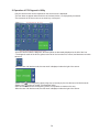
2. Operation of PC-Diagnostic Utility
-Only the device which can be inspected on the entire screen is displayed.
-The item does not appear when the device of wireless LAN etc. is not physically connected.
-The movement of the item must use an arrow key or a flat pad.
-As for the device under the diagnosis, blue and yellow are alternately displayed at the left of the icon.
- The diagnosis result of the device greens at the left of the icon when it is normal, and becomes red when
abnormal.
-When the test of all devices ends, the test result is displayed under the right of the screen.
-Please click
while diagnosing when being stop on the way by the time the test of all devices ends.
-Please click
when you restart "PC-Diagnostic utility".
*Each device is tested from the beginning, and it is not possible to restart on the way.
-When the test of all devices ends, the test result is displayed under the right of the screen.
7-2
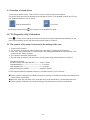
2-1. Selection of tested device
-To test only a specific device, "Test" and "Do not test" of each device can be selected.
-The device which can select the enhancing test changes in order of "The standard is tested" and "Do not
test" whenever the device icon is clicked.
Start the standard test
Please begin testing clicking
Do not test
if the selection of the tested device ends.
2-2. "PC-Diagnostic utility" End method
When
of "Close" on the right of the screen is clicked, the computer reactivates automatically. Or, the
power supply switch is done in the slide and the power supply is turned off.
2-3. The content of the setup is returned to the setting of the user
1. Turned on the computer.
2. "F2" is pushed on the screen while "Press<F2>to enter Setup" is displayed of "Panasonic".
3. Push "F10", and on the screen of "Is the change in the setting preserved and do end?"and then "Yes"
is selected, and "Enter" is pushed.
4. The computer reactivates automatically.
5. The end option is chosen by the start menu, and the power supply of the computer is turned off.
Standard at test time
All devices other than RAM and HDD ---------- about 1 minute
RAM standard test ----------------------------------- 1 - 2 minutes
HDD standard test ----------------------------------- 2 - 3 minutes
HDD enhancing test (60GB) ---------------------- about 40 minutes
Ex.The standard when the standard <all device> is tested becomes 1+2+3=6 minutes.
■ There is greatly a difference from RAM test when the memory is increased according to the performance
of the memory occasionally.
■ Moreover, when the main body of PC under the test is a high temperature, it occasionally takes time.
■ There is greatly a difference from HDD according to the performance of the drive occasionally.
7-3
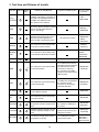
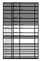
3. Test Item and Division of trouble
Test item Stanard Enhancing
Content of standard test
Content of enhancing test
Place with possibility of breakdown
CPU /
SYSTEM
CPU is shifted to protected mode, and
"Violation of the paging", "Operation of
the violation of a privileged instruction",
and DMA, INT, TIMER, and the
RTC operation are confirmed.
CPU /
Main board
RAM
All memory space is tested in a special
memory access pattern based on
"R.S.T . technology".
Memory /
Mainboard
The record area frequently accessed
with Microsoft Windows XP to test in
about two minutes regardless of
points of HDD is emphatically tested.
HDD /
Mainboard /
Cable /
Connector
HDD
MODEM
It is confirmed not to find abnormality
in the AC97 modem controller.
Wireless
LAN
It is confirmed not to find abnormality
in the Wireless LAN modem controller.
All record area is tested.
MODEM/
Mainboard
Wireless LAN
board /
Connector /
Mainboard
Sound *5
*1
USB
*2
It is confirmed not to find abnormality
in the USB controller.
It is confirmed not to find abnormalityin the wiring between
the USB controller and the
connector by confirming
the connection of the USB
equipment connected with the
USB connector.
It is confirmed not to find abnormalityin the wiring between
the controller and the
connector by connecting to
HUB with LAN cable.
Mainboard /
Connector
Mainboard /
Connector
LAN
It is confirmed not to find abnormality
in the LAN controller.
PC Card
It is confirmed not to find abnormality
in the CardBus controller.
Mainboard
SD
It is confirmed not to find abnormality
in the SD controller.
Mainboard
Keyboard
Touch Pad
DVD-ROM
*3
It is confirmed not to find abnormality
in keyboard controller's keyboard interface.
The key is actually input, and
the operation is displayed on
the screen.
Mainboard /
Keyboard
*4
Whether keyboard controller's mouse
interface operates normally is confirmed.
The operation is actually displayed on the screen by operating the touch pad.
Mainboard /
Touch Pad
*6
The drive is normally reset, and it is
accessible is confirmed.
It is confirmed to be able to
read media normally.
7-4
Mainboard /
DVD Drive /
DVD Cable /
DVD Connector
Test Item
Standard Enhanced
Content of Standard Test
It is confirmed not to find
abnormality in the USB
connection of Touch Screen.
This test cannot find
abnormality of Touch Screen.
It is confirmed not to find
abnormality in the connection
of Main board and Bluetooth
module.
It is confirmed not to find
abnormality in the connection
of Main board and Wireless
WAN module.
It is confirmed not to find
abnormality in the legacy FD
drive.
This test cannot find
abnormality of mechanical
breakdown. (e.g.. Head, Motor)
It is confirmed not to find
abnormality in access to
VRAM with VESA.
The PC which uses main
memory as VRAM may fail with
main memory failure.
It is confirmed not to find
abnormality in the connection
of Main board and GPS
It is confirmed not to find
abnormality in the IEEE1394
controller.
Touch Screen
Bluetooth
Wireless WAN
Floppy
Video
GPS
IEEE1394
Perform Touch Screen
functionality practically.
Operator has to judge
PASS/FAIL with test result.
Smart Card
It is confirmed not to find
abnormality in the Smart Card
controller.
Serial Port
*7
It is confirmed not to find
abnormality of Super I/O
UART function.
This test cannot find lack of
wiring between Super I/O and
Serial Connector.
*8
It is confirmed not to find
abnormality of Super I/O
parallel function.
This test cannot find lack of
wiring between Super I/O and
Parallel Connector.
*1
*2
*3
*4
*5
The place with possibility of
breakdown
Main board/
Touch Screen
Bluetooth cable
WWAN cable
FD Drive/
Main board (Super I/O)/
FDD cable
FDD connector
Main board
(Chipset, Graphic
Controller)/
Memory
GPS cable
Main board
(IEEE#394 Controller)
It is confirmed not to find
abnormality in the wiring
between Chipset and Express
Card.
Express Card
Parallel Port
Content of Extend Test
Main board (Chipset)/
Express Card Connector
Main board
(Smart Card Controller)
It is confirmed not to find
abnormality in the wiring
between Super I/O and Serial
Connector.
This test cannot find failure of
cable characteristic and device
problems.
It is confirmed not to find
abnormality in the wiring
between Super I/O and
Parallel Connector.
This test cannot find failure of
cable characteristic and device
problems.
Main board (Super I/O)/
Serial Connector
Main board (Super I/O)/
Parallel Connector
Please connect the USB device with the port (USB connector) which wants to test before the tests.
Please connect LAN port with LAN HUB with LAN cable before the tests.
The operator actually inputs the key, and the operator judges PASS/FAIL of the test.
The operator actually operates the mouse, and the operator judges PASS/FAIL of the test.
It is not abnormal though the sound is emitted from the speaker while testing.
When the test result is PASS, trouble is thought by not hearing of the sound under the test from
the speaker and the headphone by the wiring of the audio output system.
*6 Please set DVD/CD media in the drive before the tests.
*7 Please set a Special Loop Back Connector Tool at serial connector for Enhanced Test.
(This Connector Tool is same as the one used before.)
*8 Please set a Special Loop Back Connector Tool at parallel connector for Enhanced Test.
(This Connector Tools is same as the one used before.)
7-5
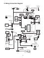
8 Wiring Connection Diagram
SPEAKER (R)
SPEAKER (L)
SERIAL PCB
SW LED MDC PCB
CN4000
CN4001
CN4201
SERIAL PORT
CN4200
CN4202
CN4203
LCD
INVERTER
EX/PC CARD
EJECTOR
EXTERNAL
DISPLAY
Connector by Cable
Direct connection by Connectors
CN28
USB
USB
CN30
CN29
EXPANTION
BUS
MODEM
Parts on Bottom Side
JK1000
CN31
CN5
CN36
DC-IN
CN35
FAN
MAIN PCB
CN16
USB
CN15
USB
CN18
CN7
CN5000
IEEE1394
CN9
DIMM MEMORY CARD
CN10
CN19
CN4
LITHIUM
BATTERY
CN3
CN33
CN2
BT PCB
DVD DRIVE
KEYBOARD
CN22
CN34
ANTENNA
PWB L
KBD FPC
CN21
ANTENNA
PWB R
CN13
HDD
SD PCB
SC RELAY PCB
CN1000
CN4300
BATT FPC
CN6503
CN7002
CN27
SD
CN25
CN3401
CN14
CN9000
CN23
JK7001 JK7003
JK7002
JK7004
BIOS PCB
TOUCH PAD PCB
WWAN PCB
CN4100
CN4101
PWR BATT
LED PCB
WIRELESS
LAN MODULE
PAD
CN4400
AUDIO PCB
JK3004 JK3003
CN3000
Microphone
Headphone
8-1
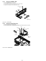
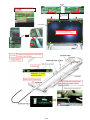
9 Disassembly/Reassembly
Note:
Power off the computer. Do not shut down to the Suspend or hibernation mode.
Do not add peripherals while the computer is in the Suspend or hibernation mode; abnormal operation may result.
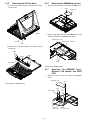
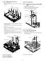
9.1.
9.1.1.
Disassembly Instructions
Disassembly Flowchart
The chart below shows the various parts which should be removed in order to remove the parts that are to be replaced.
Parts can be replaced efficiently be following the disassembly
steps in the chart.
9.1.3.1. Battery Pack
9.1.3.3. DVD Multi Drive
9.1.3.2. HDD Mounting Kit
▼
9.1.4. HDD
▼
9.1.5. Tilt Panel Ass'y
▼
▼
9.1.8. Display Unit
9.1.6. DIMM Memory Card
9.1.7. ROBSON Cover, Wireless
LAN Module and BIOS PCB
9.1.10. Handle Ass'y
9.1.9. LCD Unit, Inverter Ass'y,
and ANTENNA PWB L, R
▼
9.1.11. Modem
▼
9.1.12. SW LED MDC PCB,
Speaker L and R
▼
9.1.13. Keyboard
▼
9.1.14. Top Cover
▼
9.1.15. Pad and TOUCH
PAD PCB
▼
9.1.20. KBD Earth Plate
▼
9.1.19. PWR BATTERY
LED PCB
▼
9.1.18. AUDIO PCB
▼
9.1.22. Fan Ass'y
▼
9.1.21. Hinge Support R
▼
9.1.24. Battery Connector
Ass'y
▼
9.1.17. WWAN PCB
▼
9.1.16. SD PCB
▼
9.1.25. SC RELAY PCB
and HDD Hold Plate
▼
9.1.26. Heat Sink Ass'y
▼
9.1.23. Hinge support L
and MP Hold Plate
▼
9.1.27. SERIAL PCB
▼
9.1.28. MAIN HIGH PCB
9-1
9.1.2.
Preparation
9.1.3.2.
Before disassembling, be sure to make the following preparations.
• Shut down Windows and turn off the power.
• Disconnect the AC adaptor.
• Remove the optional DIMM memory card and PCMCIA card
if they are connected.
• Remove other devices if they are connected.
Attention:
• Please execute writing BIOS ID when you exchange the
Main Board.
• You cannot reuse the Conductive Clothes and the heat dissipating parts such as Sheet and Rubber. Use new parts.
9.1.3.
HDD Mounting Kit
1. Pull out the HDD Mounting Kit with sliding the Lock Knob
(HDD).
9.1.3.3.
DVD Multi Drive
1. Pull out the DVD Multi Drive with pushing the MP Latch.
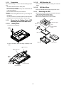
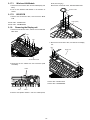
9.1.4.
Removing the HDD
1. Remove the six Hooks, and remove the HDD Case Upper
, HDD case and HDD Insulation Sheet.
2. Remove the HDD from the HDD Dumper.
3. Disconnect the HDD FPC Ass’y from the HDD.
Hook
Removing the Battery Pack, HDD
Mounting Kit and DVD Multi Drive
Hook
9.1.3.1.
Battery Pack
HDD FPC
ass'y
1. Remove the Cover Battery.
HDD case upper
Hook
HDD insulation
sheet
Cover
battery
HDD
HDD case
2. Pull out the Battery Pack with sliding the Battery Latch
Knob.
HDD mounting
kit
Battery latch knob
Battery
pack
Lock knob (HDD)
MP latch
DVD multi drive
9-2
HDD damper
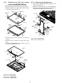
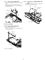
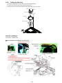
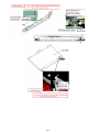
9.1.5.
Removing the Tilt Panl Ass’y
9.1.6.
1. Turn the Cover down and pull the Tilt Panel in the direction of arrows.
Removing the DIMM Memory Card
1. Remove the Screw <N10>, and remove the DIMM Cover.
<N10>
Tilt panel
DIMM cover
2. Open the right and left Hooks of the DIMM Memory Card
outward, and remove the DIMM Memory Card.
DIMM memory card
Tilt panel
DIMM memory connector
Cover
2. Remove the five Screws <N202>, and remove the Tilt
Panel Ass’y.
<N202>
<N202>
<N202>
Hook
Tilt panel ass'y
Screws <N10>: DRSB2+3FKLT
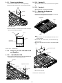
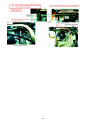
9.1.7.
Removing the ROBSON Cover,
Wireless LAN Module and BIOS
PCB
1. Remove the Screw <N3>, and remove the ROBSON
Cover.
ROBSON cover
<N3>
Screws <N202> : DRSB2+4FKLT
<N2>
BIOS PCB
Wireless
LAN module
9-3
<N2>
Cables
(Gray and blue)
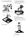
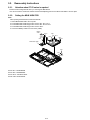
9.1.7.1.
Wireless LAN Module
white, blue and grey).
Remove the two Screws <N2>, and BIOS HIGH PCB.
1. Remove the two Screws <N2> and two Cables(Gray and
Blue).
2. Pull out the Wireless LAN Module in the direction of
Speaker holder
arrows.
9.1.7.2.
<N2>
BIOS PCB
1. Remove the two Screws <N2>, and remove the BIOS
PCB.
Cable (black)
Screws <N2> : DFHE5122YA
Screws <N3> : DRHM0065ZA
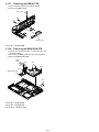
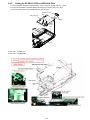
9.1.8.
Removing the Display unit
1. Remove the six Screws <N2>, and turn over the SW LED
MDC PCB.
<N2>
<N2>
Cable (white)
<N2>
BIOS HIGH PCB
4. Remove the four Screws <N4>, and remove the Display
unit.
<N4>
Display unit
SW LED MDC PCB
<N4>
2. Disconnect the two Cables from the Connectors (CN5
and CN35).
Cables
Screws <N2> : DFHE5122YA
Screws <N4> : DRHM0093ZA
CN5
CN35
3. Remove the Speaker Holder L and four Cables (black,
9-4
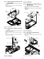
9.1.9.
Removing the LCD unit, Inverter
Ass’y and ANTENNA PWB L,R
9.1.10. Removing the Handle Ass'y
1. Remove the two Handle Sheets and two Screws <K172>,
remove the Handle Ass’y.
2. Remove the two Screws <K92-5>, and disassemble the
Handle Ass’y (Grip Upper, Grip Lower, Handle Base L,
Handle Base R, Handle Ring and Handle Pom) .
1. Remove the two LCD Rubbers and five LCD Sheets.
2. Remove the five Screws <N4> and two Screws <N15>.
3. Release the twenty-one Hooks fixing the LCD Front to the
LCD unit, remove the LCD Front.
LCD
rubber
LCD screw
sheet
LCD screw
sheet
<N4>
Grip upper
<N15>
<N15> LCD
rubber
<N4>
<N4>
<N4>
Handle
ring
LCD screw
sheet
<N4>
Handle
pom
Handle
ring
Handle
base L
LCD front
Hooks
Hooks
Handle
<K172>
sheet
Handle
ring
Hooks
<K172>
Handle
sheet
Handle
ring
Grip
lower
Hooks
<K92-5>
Hooks
Hooks
4. Remove the Screw <N12> and Tape, and remove the
LCD unit.
5. Disconnect the two Cables, and remove the Inverter
Ass’y.
6. Remove the eleven Tapes and two Screws <N2>, and
remove the ANTENNA PWB L, R.
Screws <K92-5>: DRSB3+8FKLT
Screws <K172>: DRYN4+J12KLT
LCD unit
<N12>
Cable
Tape
Inverter
ass'y
Cable
<N2>
LCD rear cover
ANTENNA
PWB L
ANTENNA
PWB R
<N2>
Screws <N2> : DFHE5122YA
Screws <N4> : DRHM0093ZA
Screws <N12> : DXSB2+4FNLT
Screws <N15> : XQN17+BJ6FJ
9-5
Handle
pom
Handle
base R
9.1.11.
Removing the Modem
9.1.12.2. Speaker R
1. Disconnect the Cable from the Connecor(CN4200).
2. Remove the two Screws <N2>, and remove the Modem.
1. Remove the Speaker Holder R, and remove the Speaker
R
9.1.12.3. Speaker L
<N2>
1. Remove the Tape, and remove the Speaker L.
Cable
9.1.13. Removing the Keyboard
Modem
1. Remove the two Tapes.
2. Lift the upper part of the Keyboard and draw it backward,
and then turn the Keyboard over forward.
CN4200
Keyboard
Tape
SW LED MDC PCB
3. Remove the Tape1, Conductive tape-modem and Tape2,
disconnect the Cable from Modem
Cable
Tape 2
Tape
Note:
Take extreme care when peeling off the tape as it is
strongly sticked.
3. Remove the four Screws <N2>, and remove the Keyboard Lid Plate.
4. Disconnect the two FPC from the two Connectors (KBD
FPC).
Tape 1
Conductive
tape-modem
<N2>
<N2>
<N2>
Screws <N2> : DFHE5122YA
Key board lid plate
<N2>
9.1.12. Removing the SW LED MDC PCB
and Speakers
Connectors
9.1.12.1. SW LED MDC PCB
1. Disconnect the Cables from the Connectors(CN4202 and
CN4203), and remove SW LED MDC PCB.
Speaker
L
Tape
Speaker holder R
Cable
CN4202
CN4203
Cable
FPC
Speaker
R
KBD FPC
5. Remove the Keyboard.
Screws <N2> : DFHE5122YA
9-6
9.1.14. Removing the Top Cover
Screws <N12> : DXSB2+4FNLT
Screws <N14> : XTB26+10GJKT
1. Remove the Gasket.
2. Remove the Screws <N2>, <N4>, <N9> and ten Screws
<N14>
9.1.15. Removing the Pad and TOUCH PAD
PCB
1. Remove the six Screws <N12>.
2. Remove the Top Relay Plate and Pad Holder.
3. Remove the Pad and TOUCH PAD PCB.
<N14>
<N4>
Gasket
<N14>
<N14>
<N12>
<N14>
<N2>
Top relay plate
<N14>
<N9>
<N12>
<N14>
Pad holder
TOUCH PAD
PCB
<N14>
Pad
3. Turn the unit to the face, remove the Screw <N12> and
five Screws <N8>.
4. Remove the WP Sheet and Tape, and remove the Screw
<N12>.
5. Remove the two Screw Sheets.
Remove the two Screws <N9>, and remove the Cover
BT.
Remove the Screw <N2> and disconnect the Cable from
the BT UNIT PCB, and remove it.
6. Disconnect the FFC and KBD FPC from the Connectors(CN23 and CN22), and lift up the Top Cover Ass’y and
remove it.
9.1.16. Removing the SD PCB
1. Remove the two Screws <N12>.
2. Disconnect the FFC from the Connector(CN4300), and
remove the SD PCB.
Screw
sheet
WP sheet
<N12>
<N9>
<N8>
<N2>
<N8>
<N12>
<N8>
SD PCB
BT UNIT
PCB
FFC
CN23
CN22
<N12>
CN4300
Cover
BT
<N2>
<N9>
Tape
Top cover ass'y
Screws <N12> : DXSB2+4FNLT
FFC
KBD FPC
Screws <N12> : DXSB2+4FNLT
Screws <N2> : DFHE5122YA
Screw <N4> : DRHM0093ZA
Screws <N8> : DRHM5054XAT
Screws <N9> : DRHM5104ZAT
9-7
9.1.17. Removing the WWAN PCB
9.1.19. Removing the PWR BATTERY LED
PCB
1. Disconnect the Cables(Gray and Blue) from the WWAN
PCB.
2. Remove the two Screws <N2> and the Screw <N9>.
3. Disconnect the FPC from the Connector(CN7002), and
remove the SD PCB.
1. Remove the PWR BATTERY LED PCB, and disconnect
the Cable from the Connector(CN4400).
Cable
PWR BATTERY
LED PCB
<N9>
<N2>
CN4400
<N2>
WWAN PCB
CN7002
Cable
(Gray)
Cable
(Blue)
Bottom case ass'y
Screws <N2> : DFHE5122YA
Screw <N9> : DRHM5104ZAT
9.1.18. Removing the AUDIO PCB
1. Remove the two Screws <N4>.
2. Disconnect the Cable from the Connector(CN3000), and
remove the AUDIO PCB.
<N4>
AUDIO PCB
CN3000
<N4>
Cable
Screw <N4> : DRHM0093ZA
9-8
9.1.20. Removing the KBD Earth Plate
9.1.21. Removing the Hinge Support R
1. Remove the Tape in the direction of arrow.
Tape
1. Peel off the Tape and remove the Screw <N4>.
2. Disconnect the Cable from the Connector (CN7).
3. Turn the Cover PC Card down in the direction of arrow,
and remove the Hinge Support R.
FFC
CN34
Tape
<N4>
Hinge support R
2. Remove the four Screws <N4> and two Screws <N13>,
and remove the KBD Earth Plate.
<N13>
<N4>
CN7
KBD EARTH
PLATE
Cover PC card
<N4>
Screw <N4> : DRHM0093ZA
9.1.22. Removing the Fan Ass’y
1. Disconnect the Cable from the Connector(CN18).
2. Remove the two Screws <N4>, and remove the Fan
Ass’y.
3. Remove the three Screws <N12>, and remove the Fan.
4. Remove the three Screws <N2>, and remove the Fan
Case Plate.
<N12>
<N12>
<N12>
Fan
<N4>
Screw <N4> : DRHM0093ZA
Screw <N13> : DXYN2+F12FNL
Fan case
Fan case plate
<N2> <N2>
Screw <N2> : DFHE5122YA
Screw <N4> : DRHM0093ZA
Screw <N12> : DXSB2+4FNLT
9-9
9.1.23. Removing the Hinge Support L and
MP Hold Plate
1. Peel off the three Tapes and remove the two Cables(Gray
and Blue).
2. Remove the six Screws <N4>, remove the Hinge Support
L and MP Hold Plate.
Cables
<N4>
(Gray and
Blue)
<N4>
Screw <N5> : DRHM0112ZA
Screw <N6> : DRHM0115ZA
9.1.25. Removing the SC RELAY PCB and
HDD Hold Plate
1. Disconnect the FFC from the Connector(CN6503).
2. Remove the two Screws <N2>, and remove the SC
RELAY PCB.
3. Remove the two Screws <N4>, and remove the HDD
Hold Plate.
<N4>
Tapes
Hinge
support L
SC RELAY PCB
<N4>
HDD hold plate
<N2>
<N4>
<N4>
<N4>
CN6503
<N4>
MP hold
plate
Tape
FFC
Screw <N4> : DRHM0093ZA
9.1.24. Removing the Battery Connector
Ass’y
1. Remove the two Screws <N2> and <N4>, and remove
the Battery Connector Ass’y.
2. Remove the two Screws <N6>, and remove the Batt FPC
Plate.
3. Remove the two Screws <N5>, and remove the Batt Con
Holder from the FPC Batt.
<N4>
Screw <N2> : DFHE5122YA
Screw <N4> : DRHM0093ZA
9.1.26. Removing the Heat Sink Ass’y
1. Remove the Fan Duct.
2. Remove the four Screws <K138>, and remove the Heat
Sink Ass’y.
<N6>
<K138>
<N4>
Batt FPC plate
<N5>
<K138>
<N2>
FPC batt
Batt con holder
Fan duct
Heat sink
ass'y
Screw <N2> : DFHE5122YA
Screw <N4> : DRHM0093ZA
Screw <K138> : DRHM0119ZAT
9-10
9.1.27. Removing the SERIAL PCB
1. Remove the two Screws <N1> and Hex Spacer.
2. Remove the SERIAL PCB.
Hex spacer
<N1>
<N1>
SERIAL PCB
Screw <N1> : DFHE5035ZB
9.1.28. Removing the MAIN HIGH PCB
1. Remove the two Screws <N1>, four Screws <N4> and
two Screws <N13>.
2. Disconnect the Battery Cable from the Connector(CN4).
3. Remove the MAIN HIGH PCB.
Battery
cable
<N13>
<N4>
<N4>
<N4>
CN4
MAIN HIGH PCB
<N1>
Screw <N1> : DFHE5035ZB
Screw <N4> : DRHM0093ZA
Screw <N13> : DXYN2+F12FNL
9-11
9.2.
9.2.1.
Reassembly Instructions
Attention when CF-52 series is repaired
• Please execute writing BIOS ID when you exchange the Main Board.
• You cannot reuse the Conductive Clothes and the heat dissipating parts such as Sheet and Rubber. Use new parts.
9.2.2.
Setting the MAIN HIGH PCB
Note:
After replacing the Main Board, rewrite the BIOS ID.
1. Set the MAIN HIGH PCB to the computer.
2. Fix the MAIN HIGH PCB using the two Screws <N1>. No.1, No.2
3. Fix the MAIN HIGH PCB using the two Screws <N4>. No.3 to No.6
4. Fix the MAIN HIGH PCB using the two Screws <N13>.
5. Connect the Battery Cable to the Connector (CN42).
Battery
cable
<N13>
<N4>
:No.4
<N4>
:No.5
:No.6
CN4
<N4>
:No.3
MAIN HIGH PCB
<N1>
:No.1
:No.2
Screw <N1> : DFHE5035ZB
Screw <N4> : DRHM0093ZA
Screw <N13> : DXYN2+F12FNL
Screws <N9>: DFHE5025XA
9-12
■ Setting of Main PCB before assembling.
9-13
9-14
9.2.3.
Setting the SERIAL PCB
1. Set the SERIAL PCB to the computer.
2. Fix the SERIAL PCB using the two Screws <N1>. No1, No.2
3. Tighten the Hex Spacer to the SERIAL PCB. No.3
Hex spacer
:No.3
<N1>
<N1>
:No.2
:No.1
SERIAL PCB
Screw <N1> : DFHE5035ZB
9.2.4.
Setting the Heat Sink Ass’y
1. Set the Fan Duct to the Heat Sink Ass’y.
2. Fix the Heat Sink Ass’y to the MAIN PCB using the four Screws <K138>. No.1 to No.4
:No.3
<K138>
:No.1
<K138>
:No.2
:No.4
Fan duct
Heat sink
ass'y
Screw <K138> : DRHM0119ZAT
9-15
9.2.5.
Setting the Fan Ass’y
1. Fix the Fan Case Plate to the Fan Case using the three Screws <N2>.
2. Fix the Fan to the Fan Case using the three Screws <N12>.
3. Set the Fan Ass’y to the computer, and fix it using two Screws <N4>. No.1, No.2
<N12>
<N12>
<N12>
Fan
<N4>
Fan case
Fan case plate
<N2> <N2>
Screw <N2> : DFHE5122YA
Screw <N4> : DRHM0093ZA
Screw <N12> : DXSB2+4FNLT
■How to assemble the Heat Sink Ass’y and Fan Ass’y.
9-16
9-17
9.2.6.
Setting the SC RELAY PCB and HDD Hold Plate
1. Set the SC REALY PCB to the HDD Hold Plate, and fix it using two Screws <N2>. No.1, No.2
2. Fix the HDD Hold Plate to the MAIN HIGH PCB using the two Screws <N4>. No.3, No.4
3. Connect the FFC to the Connector(CN6503) and paste the Tape.
SC RELAY PCB
HDD hold plate
<N2>
<N4>
:No.1
CN6503
<N4>
:No.2
Tape
FFC
Screws <N2> : DFHE5122YA
Screws <N4> : DRHM0093ZA
9-18
9.2.7.
1.
2.
3.
4.
Setting the Battery Connector Ass’y
Fix the Batt Con Holder to the FPC Batt using the two Screws <N5>.
Fix the Batt Con Holder to the Batt FPC Plate using the two Screws <N6>.
Fix the Batt FPC Plate to the computer using the two Screws <N4>. No.1, No.2
Connect the FPC Batt’s connector to the connector(CN1000), and fix the FPC Batt to the MAIN HIGH PCB using the two
Screws <N2>. No.1, No.2
<N4>:No.4
<N6>
<N4>:No.3
Batt FPC plate
<N5>
<N2> :No.1
<N2> :No.2
Batt con holder
FPC batt
Screw <N2> : DFHE5122YA
Screw <N4> : DRHM0093ZA
Screw <N5> : DRHM0112ZA
Screw <N6> : DRHM0115ZA
9.2.8.
Setting the Hinge Support L and MP Hold Plate
1. Set the Hinge Support L and MP Hold Plate to the computer.
2. Fix the Hinge Support L and MP Hold Plate using the six Screws <N4>. No.1 to No.6
3. Paste the Tapes.
<N4>
:No.7
Hinge
<N4>
support L :No.2
Cables
<N4> :No.1
<N4> (Gray and
<N4>
:No.5 Blue)
:No.6
Tapes
<N4>
:No.4
<N4>
:No.3
MP hold
plate
Screw <N4> : DRHM0093ZA
9-19
9.2.9.
Setting the Hinge Cover R
1. Place the Cable through the rectangled hole of Hinge Support R and connect the Cable to the Connector (CN7).
2. Fix the Hinge Support R to the computer using the Screw <N4>.
<N4>
Tape
Hinge support R
CN7
Screw <N4> : DRHM0093ZA
■How to place the Cable
9-20
Cover PC card
9.2.10. Setting the KBD Earth Plate
1. Set the KBD Earth Plate to the computer.
2. Fix the KBD Earth Plate using the four Screws <N4>. No.1 to No.4
3. Fix the KBD Earth Plate using the two Screws<N13>.
<N13>
<N4>:No.3
<N4>:No.2
<N4>:No.1
KBD EARTH
PLATE
<N4>:No.4
4. Paste the tape, and connect the FPC to the Connector(CN34).
Tape
CN34
Screw <N4> : DRHM0093ZA
Screw <N13> : DXYN2+F12FNL
9-21
FFC
9.2.11.
Setting the PWR BATTERY LED PCB
1. Connect the Cabel to the Connector(CN4400), and insert it to the computer.
Cable
CN4400
PWR BATTERY
LED PCB
Bottom case ass'y
9-22
9.2.12. Setting the AUDIO PCB
1. Connect the Cable to the Connector(CN3000).
2. Set the AUDIO PCB to the computer, and fix it using the two Screws <N4>. No.1, No.2
<N4>:No.1
AUDIO PCB
CN3000
<N4>:No.2
Cable
Screw <N4> : DRHM0093ZA
■Arranging the Cable and setting the WL button.
9-23
9.2.13. Setting the WWAN PCB
1. Connect the FPC to the Connector(CN7002).
2. Set the WWAN PCB, and fix it using two Screws <N2> and the Screw <N9>. No.1 to No.3
3. Connect the Cable(Gray) to JK7002 and Cable(Blue) to JK7004.
<N2>:No.2
<N9>:No.3
<N2>:No.1
WWAN PCB
CN7002
Cable
(Gray)
Cable
(Blue)
Screw <N2> : DFHE5122YA
Screw <N9> : DRHM5104ZAT
■Arranging the Cables and Tapes
9-24
9.2.14. Setting the SD PCB
1. Connect the FFC to the Connector(CN4300).
2. Set the SD PCB to the Top Cover, and fix it to using the two Screws <N12>. No.1, No.2
<N12>
<N12>
CN4300
SD PCB
FFC
Screw <N12> : DXSB2+4FNLT
9.2.15. Setting the Pad and TOUCH PAD PCB
1. Paste the Pad and set the TOUCH PAD PCB to the Top Cover.
2. Set the Pad Holder and Top Relay Plate, and fix them using the six Screws <N12>. No.1 to No.6
<N12>:No.2
Top relay plate
<N12>:No.5
<N12>:No.1
<N12>:No.6
<N12>:No.3
<N12>:No.4
Pad holder
TOUCH PAD
PCB
Pad
Screw <N12> : DXSB2+4FNLT
9-25
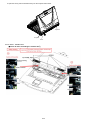
9.2.16. Setting the Top Cover
1.
2.
3.
4.
Connect the KBD FPC and FFC to the Connectors(CN22 and CN23), and place the Top Cover on the computer.
Fix the Top Cover using the five Screws <N8>. No.1 to No.5
Fix the Top Cover using the Screw <N12>.
Fix the BT UNIT PCB to the Top Cover using the Screw <N2> and connect the Cable to the connector.
Screw
sheet
WP sheet
<N9>:No.1
Cover
BT
<N2>
<N9>
:No.2
Tape
Top cover ass'y <N8>:No.1
<N2>
<N8>:No.3
<N8>
:No.4
<N12>
BT UNIT
PCB
<N8>
:No.2
<N8>
:No.5
FFC
CN23
KBD FPC
CN22
5.
6.
7.
8.
9.
Fix the Top Cover using the Screw <N2>, and paste the Tape and WP Sheet on it.
Fix the Cover BT to the Top Cover using the two Screws <N9> No.1, No.2, and paste the Screw Sheet on the Screws.
Fix the Bottom Case to the Top Cover using the Screw <N2>, <N4> and ten Screws <N14>. No.1 to No.12
Fix the Bottom Case using the Screw <N9>.
Paste the Gasket on the Screw <N14>.
<N14>
:No.2
<N14>
:No.9
<N4>:No.11
Gasket
<N14>
:No.3
<N14>
:No.10
<N2>
:No.12
<N14>
:No.5
<N14>:No.8
<N14> <N14>
:No.7 :No.4
<N9>
<N14>
:No.6
<N14>
:No.1
Screws <N2> : DFHE5122YA
Screw <N4> : DRHM0093ZA
Screws <N8> : DRHM5054XAT
Screws <N9> : DRHM5104ZAT
Screws <N12> : DXSB2+4FNLT
Screws <N14> : XTB26+10GJKT
9-26
9.2.17. Setting the Keyboard
1. Connect the FPCs to the Connector on the KBD FPC.
2. Place the Keyboard Lid Plate on the Top Cover, and fix it using the four Screws <N2>. No.1 to No.4
<N2>:No.2
<N2>:No.3
<N2>:No.4
Key board lid plate
<N2>:No.1
Connectors
FPC
KBD FPC
3. Place the Keyboard on the Top Cover and paste the Tapes.
Keyboard
Tape
Tape
Screws <N2> : DFHE5122YA
9-27
■Caution for when assembling the Keyboard.
9-28
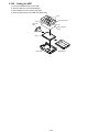
9.2.18. Setting the Speakers
1.
2.
3.
4.
Place the Speakers on the computer.
Connect the Cables to the Connector(CN4202 and CN4203).
Paste the Tape on the Cable.
Attach the Speaker Holder R to the computer.
Speaker
L
Tape
Speaker holder R
Cable
CN4202
CN4203
Cable
Note:
Do not attach the Speaker Holder L to the computer yet.
9.2.19. Setting the Modem
1. Connect the Cable to the Connector.
2. Paste the Tape2, Conductive Tape-Modem and Tape1.
3. Fix the Modem to the SW LED MDC PCB using the two Screws <N2>.
<N2>
Cable
Modem
CN4200
SW LED MDC PCB
Screws <N2> : DFHE5122YA
9-29
Speaker
R
■How to paste the Tape
9-30
9.2.20. Setting the Handle Ass’y
1. Assemle the Handle Ass’y (Grip Upper, Grip Lower, Handle Base L, Handle Base R, Handle Ring and Handle Pom), and fix
them using the two Screws <K92-5>.
2. Fix the Handle Base Ass’y to the computer using the two Screws <K172>.
Paste the Handle Sheet on the Screws <K172>.
Grip upper
Handle
ring
Handle
pom
Handle
ring
Handle
base L
Handle
<K172>
sheet
Handle
ring
Handle
pom
<K172>
Handle
sheet
Handle
ring
Grip
lower
<K92-5>
Screws <K92-5>: DRSB3+8FKLT
Screws <K172>: DRYN4+J12KLT
9-31
Handle
base R
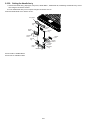
9.2.21. Setting the LCD Unit, Inverter Ass’y and Antenna PWB L, R
1. Set the LCD Unit to the LCD Rear Cover
2. Fix the Inverter Ass’y using the Screw <N12>.
3. Fix the Anttena PWB L and R using the Screws <N2>.
LCD unit
<N12>
Cable
Tape
Inverter
ass'y
Cable
ANTENNA
PWB L
<N2>
ANTENNA
PWB R
LCD rear cover
<N2>
4. Place the LCD Front on the LCD Rear Case.
Confirm that the twenty-one Hooks are fixed perfectly.
5. Fix the LCD Front using the five Screws <N4> and two Screws <N15>.
6. Paste the LCD Screw Sheet and LCD Rubber.
LCD screw
sheet
LCD
rubber
<N4>
LCD screw
sheet
<N15>
<N15> LCD
rubber
<N4>
<N4>
<N4>
LCD screw
sheet
<N4>
LCD front
Hooks
Hooks
Hooks
Hooks
Hooks
Hooks
Screws <N2> : DFHE5122YA
Screw <N4> : DRHM0093ZA
Screws <N12> : DXSB2+4FNLT
Screws <N15> : XQN17+BJ6FJ
9-32
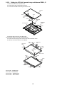
■Setting of LCD unit ass’y
LCD DAMPER D
Using JIG
LCD
LCD DAMPER A
LCD DAMPER B
Gasket
LCD DAMPER C
LCD
Gap within 0.5mm
Using JIG
Alminium (silvery) paster is stuck on the gasket.
th
Gasket
Paster
LCD
Pressurizing range
SHIELD SHEET A
LCD
Schematic for sticking at Point A
A
A
SHIELD SHEET B
SHEET
Insert LCD CABLE surely
A
LCD CABLE
Range of
pressurizing
LCD SHEET
A
70mm
The cloth conductor shall be stuck along the gasket.
9-33
Bending
ADHESIVE TAPE B
ADHESIVE TAPE B
ADHESIVE TAPE A
Do not exceed
the edge.
Do not exceed
the edge.
5
8mm
Do not exceed
the edge.
9-34
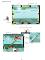
Safety Working
CAUTION
S1:Insulation S2:Pinching Cables S3:Sharp Edge
S4:Part No. Check S5:Others
The Cable is under
the base plate
Along the slot
SCREW
PWB ANT L
Along the slot
SCREW
PWB ANT R
Tape shall not cover the round hole
Tape shall not cover the round hole
LCD REAR COVER
TAPE
S5
20mm
20mm
LCD DAMPER E
LCD DAMPER E
TAPE
SCREW
HINGE L
S5
Attention: The heat-resistant adhesive tape
shall be stuck onto the part surely.
9-35
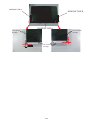
SCREW
HINGE R
SHEET
Note: Paster shall be firmly stuck and
does not float.
Note:
Do not exceed the
edge of the metal
frame
LCD ASS'Y
There are total 12 gaskets indicated by yellow
arrows which must be installed surely.
Refer to the specification pictures on the left.
OK
NG
9-36
9-37
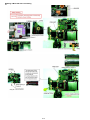
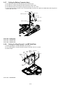
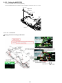
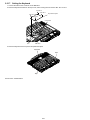
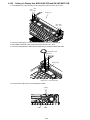
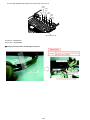
9.2.22. Setting the Display Unit, BIOS HIGH PCB and SW LED MDC PCB
1. Set the Display Unit to the computer, and fix it using the four Screws <N4>. No.1 to No.4
<N4> <N4>
:No.2 :No.1
Display unit
<N4> <N4>
:No.4 :No.3
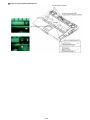
2. Connect the Cable(gray) to JK7001 and the Cable(blue) to JK7003 on WWAN PCB.
3. Set the BIOS HIGH PCB, and fix it using the two Screws<N2>. No.1, No.2
4. Connect the Cable(black) to JK6103 and the Cable(white) to JK6102 on BIOS HIGH PCB.
Speaker holder
<N2>:No.2
<N2>:No.1
Cable (black)
Cable (white)
5. Connect the two Cables to the Connector(CN5 and CN35).
Cables
CN5
CN35
9-38
BIOS HIGH PCB
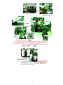
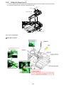
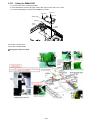
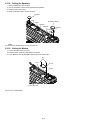
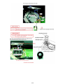
6. Fix the SW LED MDC PCB using the six Screws <N2>. No.1 to No.6
<N2>
:No.6
<N2>
:No.2
<N2>
:No.3
<N2>
:No.5
<N2>
:No.4
<N2>
:No.1
SW LED MDC PCB
Screw<N2> : DFHE5122YA
Screw <N4> : DRHM0093ZA
■Arranging the Cables when assembling the LCD Unit.
9-39
9-40
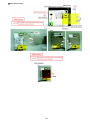
■Arranging the Speaker Cables when assembling the SW LED MDC PCB.
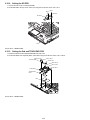
9.2.23. Setting the Wireless LAN Module, BIOS PCB and ROBSON Cover
1. Put the Wireless LAN Module into the connector at an angle of fourty-five degrees.
2. Attach the BIOS PCB to the MAIN HIGH PCB, fix it using the two Screws <N2>.
3. Set the ROBSON Cover, and fix it using the Screw <N3>.
ROBSON cover
<N3>
<N2>
BIOS PCB
Wireless
LAN module
<N2>
Cables
(Gray and blue)
Screw <N2> : DFHE5122YA
Screw <N3> : DRHM0065ZA
9-41
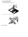
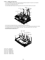
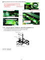
9.2.24. Setting the DIMM Memory Card and DIMM Cover
1. Put the DIMM Memory Card into the connector.
2. Close the right and left Hooks, and paste the Tape.
DIMM memory card
DIMM memory connector
Hook
3. Set the DIMM Memory Card, and fix it using the Screw <N10>.
<N10>
DIMM cover
Screw <N10> : DRSB2+3FKLT
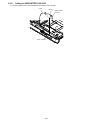
9.2.25. Setting the Tilt Panel Ass’y
1. Set the Tilt Panel Ass’y to the computer, and fix it using the five Screws <N202>.
<N202>
<N202>
Tilt panel ass'y
9-42
<N202>
2. Open the Cover, push the Tilt Panel Ass’y into the computer until it clicks.
Tilt panel
Tilt panel
Cover
Screw <N202> : DRSB2+4FKLT
■Caution for when assembling the Tilt Panel Ass’y
9-43
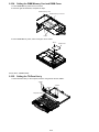
9.2.26. Setting the HDD
1.
2.
3.
4.
Connect the HDD FPC Ass’y to the HDD.
Insert the HDD Ass’y into the HDD Damper.
Set the HDD Ass’y into the HDD Case Upper.
Attach the HDD Case into the HDD Case Upper Ass’y
Hook
HDD case upper
Hook
HDD FPC
ass'y
Hook
HDD insulation
sheet
HDD
HDD damper
HDD case
9-44
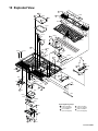
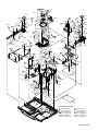
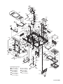
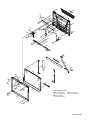
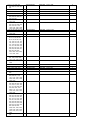
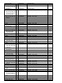
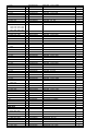
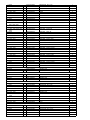
10 Exploded View
E N202
E N2
K120
E N2
E N202
K214
K213
E N2
E N2
E N202
K216
K212
K121
K215
K212
K31
K140
E N2
B N2
K218
K217
E39
E201
K211
E5
H N8
K176
K151
K175
E N12
E N2
K155
E N2
E34
H N8
N2
H N8
K154
K160
K33
E N9
K159
E N9
K30
E N2
K47
K46
K174
K44
E24
K160
E11
F N2
K45
K125
K41
K34
E6
K42
E21
K41
E N12
K32
K41
E33
K43
K35
K36
E20
K37
E4
Screw tightening torque
E18
K39
B 0.18 ± 0.02 N.m
(1.8 ± 0.2 kgf.cm)
E 0.2 ± 0.02 N.m
(2.0 ± 0.2 kgf.cm)
F 0.18 ± 0.01 N.m
(0.8 ± 0.1 kgf.cm)
H 0.44 ± 0.02 N.m
(4.4 ± 0.2 kgf.cm)
K38
K40
B N12
B N12
CF-52AJYZDZM
K95
E K93-3
K94
K93
K152
K99
K93-4
K158
K134
H N4
K98
E N4
H N4
K142
H N4
K47
K132
K143
E32
K157
H N4
K153
E29
K103
K105
K104
K139
K157 E N4 E30
H N13
K93-2
K97
K158
K142
K156
K101
K73
K141
K137
E K93-5
K138 H
K62
K136
K138
K96
K139
K145
K139
K144
F K124
K135
H
F K124
K106
K140
K131
K100
H N4
K102
K74
H N4
K123
K76
H N4
K122
H N4
K75
H N4
C N6
K80
K146
B N2
E19
K90
K78
C N5 A N2
C N5
K91
E32
K153
H K138
K104
K98
K93-1
K139
K105
H N4
N13 H
E38
K89
H
E N4
N2
K133
K77
H N4
H N4
K109
E36
H N4
H N4
E8
K107
E N13
K128
K108
E1
K79
E10
K82
K88
K88
K88 K83
K84
B N16
B N2
B N2
K83
E17
E37
E N2
K85
K86
K164
K87
K202
Screw tightening torque
A 0.3 ± 0.02 N.m
(3.0 ± 0.2 kgf.cm)
B 0.18 ± 0.02 N.m
(1.8 ± 0.2 kgf.cm)
C 0.25 ± 0.02 N.m
(2.5 ± 0.2 kgf.cm)
E 0.2 ± 0.02 N.m
(2.0 ± 0.2 kgf.cm)
F 0.18 ± 0.01 N.m
(0.8 ± 0.1 kgf.cm)
H 0.44 ± 0.02 N.m
(4.4 ± 0.2 kgf.cm)
CF-52AJYZDZM
N2
E
E10
E N9
E27
E28
E
DM1-1
N2
DM1
E31
K130
K129
E9
E25
DM5
DM3
G
G
DM6
E26
E22
K117
DM6
G DM7
DM2
E
H
N2
N11
E
E
N11
K58
K127
K126
E3
H N4
E
N11
K70
K52
K73
DM4
K147
K69
K119
K118
K63
G DM7
H N4
K149
K150
K50
K59
K81
H
N1
K51
H
E2
N14
K148
K68
K161
N2
K64
K57
K66
K54
K72 K66
J
N9
K67
K71
K65
K61
K162
H
K60
K92
N1
K73
K48
H N14
K201
K168
K92-4
K49
K92-9
K92-8
K92-2
H
K55
H
E
K92-3
E7
N14
N2
H
N14
K92-2
K92-6
H
E23
K92-2
N4
H N14
K56
K53
I
K172
K173
B
H
N14
N9
N14
H
K92-8
K170
K92-7
K173
I
K116
K113
E
N7
K221-3
K92-9
K115
K166
K165
K167
K92-1
K92-5
K50
K51
K163
K49
K92-3
K170
N14
E
K221-6
K221-5
K221-8
N7
K221-4
K172
K221-7
E202
K111
E
N3
K110
K112
K221-1
Screw tightening torque
B 0.18 ± 0.02 N.m
(1.8 ± 0.2 kgf.cm)
D 0.9 ± 0.05 N.m
(9 ± 0.5 kgf.cm)
E 0.2 ± 0.02 N.m
(2.0 ± 0.2 kgf.cm)
G 0.13 ± 0.01 N.m
(1.3 ± 0.1 kgf.cm)
H 0.44 ± 0.02 N.m
(4.4 ± 0.2 kgf.cm)
I 1.5 ± 0.1 N.m
(15 ± 1 kgf.cm)
J 0.28 ± 0.02 N.m
(2.8 ± 0.2 kgf.cm)
K221
E
N10
K114
K169
K171
E
N7
CF-52AJYZDZM
K14
K26
E16
E16-2
K14
H N4
K27
E16-1
E N2
K11
E15
K17
E15-1
H N4
K18
E15-2 K23
E N2
H N4
K15
K16
E N2
N4
K12
K13
E41
K22
E N12
H N4
N4
K20
E35
K21
K5
K4
E42
K7
K1
K8
K6
E40
K19
K25
K9
K2
B N15
H N4
K19
K3
K28
K9
K29
K29
H N4
H N4
K28
K10
Screw tightening torque
B 0.18 ± 0.02 N.m
(1.8 ± 0.2 kgf.cm)
E 0.2 ± 0.02 N.m
(2.0 ± 0.2 kgf.cm)
H N4
K29
K24
H 0.44 ± 0.02 N.m
(4.4 ± 0.2 kgf.cm)
H N4
K29
CF-52AJYZDZM
Replacement Parts List
Note : Important Safety Notice
! mark have special characteristics important for safety.
Components identified by
When replacing any of these components, use only manufacturer's specified parts.
CF-52AJYZDZM
NRP: Non Reusable Parts
REF. NO and AREA
Main Block Unit
E1
E2
E3
E4
E5
E6
E7
E8
E9
E10
E11
E15
E15-1
E15-2
E16
E16-1
E16-2
E17
E18
E19
E20
E21
E22
E23
E24
E25
E26
E27
E28
E29
E30
E31
E32
E33
E34
E35
E36
E37
E38
E39
E40
E41
E42
E201
E202
Accessories
A1
A2
A3
A4
A5
Packing Material
P1
P2
P3
P4
S
S
S
S
S
S
S
S
PART NO.
DESCRIPTION
Q'TY
DL3U11616AAA
DL3U21616AAA
DL3U31616AAA
DL3U41616AAA
DL3U51616AAA
DL3U61616AAA
DL3U71616AAA
DL3U81616AAA
DL3U91616AAA
DL3UA1616AAA
DL3UP1621AAA
DL3U11622AAA
DFJS1098ZB
DFJS1100ZA
DL3U21622AAA
DFJS1097ZB
DFJS1099ZB
N5ZZ00000128
DFJK9012YA
DFJK9014YA
DFJK9024ZB
DFJK9025ZA
DFJS1078ZA
DFJS1079ZA
DFJS1080ZA
DFJS1081ZB
DFJS1082ZB
DFJS1095ZB
DFJS1096ZC
DFJS1111ZB
DFJS1112ZB
DFUP1641ZA
L0AA02A00080
N2EAYYY00003
N5HAZ0000016
N0GF1J000011
K1NB94B00002
N5HZC0000031
DFWP0146ZA
DFWP0147ZB
L5EDDYY00060
DFJS1077YA
DFJS1128ZA
N2ABZY000035
N3CAYYY00021
PCB, MAIN HIGH
PCB, AUDIO
PCB, SERIAL
PCB, TOUCH PAD
PCB, SW LED MDC
PCB, SD
PCB, PWR BATTERY LED
PCB, SC RELAY
PCB, WWAN
PCB, BIOS HIGH
PCB, BT UNIT
ANTENNA PWB R
WLAN ANTENNA CABLE R
WWAN ANTENNA CABLE R
ANTENNA PWB L
WLAN ANTENNA CABLE L
WWAN ANTENNA CABLE L
1GB DDR2-667 SO-DIMM
FFC, PAD
FFC, SC FS
FFC, CLICK
FFC SD
SW LED I/O CABLE
AUDIO LED SW CABLE
BLUETOOTH CABLE
LAN CABLE
MODEM CABLE
CABLE ANT RELAY WLAN L
RELAY WLAN ANTENNA CABLE R
SPEAKER CABLE-L
SPEAKER CABLE-R
FPC
SPEAKER
PAD
MODEM
INVERTER
EX/PC CARD EJECTOR
WIRELESS LAN MODULE
BATTERY FPC ASS'Y
KBD SD RELAY FPC ASS'Y
LCD HIGH
INVERTER CABLE
LCD CABLE
KEYBOARD VISTA US
HDD
RTL
RTL
RTL
RTL
RTL
RTL
RTL
RTL
RTL
RTL
RTL
RTL
DFQW5048ZBT
K2CG3DR00004
CF-AA1683AMA
CGR-B/982AE
DFJS1070ZA
MANUAL(CF-52MK1 USA)
AC CORD
AC ADAPTOR
LITHIUM ION BATTERY PACK
MODEM CABLE
1
1
1
1
1
DFPN0851ZAT
DFPN0852ZAT
DFPE0873ZAT
DFPE0874ZBT
CUSHION T
CUSHION B
BATTERY HOLDER
MANUAL HOLDER
2
2
1
1
RTL
NRP
1
1
1
1
1
1
1
1
1
1
1
1
1
1
1
1
1
1
1
1
1
1
1
1
1
1
1
1
1
1
1
1
2
1
1
1
1
1
1
1
1
1
1
1
1
P5
P6
P7
P8
Mechanical Parts
K1
K2
K3
K4
K5
K6
K7
K8
K9
K10
K11
K12
K13
K14
K15
K16
K17
K18
K19
K20
K21
K22
K23
K24
K25
K26
K27
K28
K29
K30
K31
K32
K33
K34
K35
K36
K37
K38
K39
K40
K41
K42
K43
K44
K45
K46
K47
K48
K49
K50
K51
K52
K53
K54
K55
K56
K57
K58
K59
K60
K61
S
S
S
S
S
DFPE0875ZCT
DFPK1234ZAT
DFPH0077ZAT
DFPP0136ZAT
ACCESSORY HOLDER
PACKING CASE
PROTECTION SHEET
PROTECTION BAG
DFHR3G84ZB
DFHR3G85ZC
DFHR3G86ZC
DFHR3G87ZA
DFMC0770ZA
DFHE1071ZB
DFMC0889ZA
DFMC0890ZA
DFHR3J68ZA
DFHR3J67ZA
DFKF0281YA-0
DFBH1184ZB
DFBH1185ZB
DFHR3J72ZA
DFKE0900ZA-0
DFUN0086ZA
DFDF5026ZA
DFMD7B37ZA
DFHE1068ZB
DFMX1282ZC
DFQT6077YAT
DFHE1067ZA
DFHR6358ZA
DFKM0535ZE-0
DFHE0893ZA
DFGB0131YA-0
DFGX0482ZC-0
DFHG2009ZA-0
DFGX0283ZA-1
DFKA0062ZC-0
DFHR3G01ZA
DFHR3G79ZB
DFHR3G80ZB
DFHR3H76ZA
DFBC0324ZA-0
DFBC0325ZA-0
DFHR3H74ZA
DFMC0797ZA
DFHR6327ZA
DFMD7B36ZA
DFHR3H38ZA
DFMC0613ZAT
DFHR3H50ZA
DFHR6324ZA
DFMC0852ZA
DFHR3J91ZA
DFHR3J90ZA
DFKM0534ZC-0
DFHG2035ZA-0
DFHG1976ZB-0
DRHM0130ZAT
DFBD0178ZA-0
DFBD0196ZA-0
DFHR6331ZC
DFHR3H19ZB
DFHR3H20ZC
DFUQ0105ZA
DFMD7B45ZA
DFUD0043ZB
DFHG2033ZA
DFHE1064ZA
LCD DAMPER A
LCD DAMPER B
LCD DAMPER C
LCD DAMPER D
CONDUCTIVE TAPE
CONDUCTIVE TAPE
SHIELD SHEET A
SHIELD SHEET B
ADHESIVE TAPE-B
ADHESIVE TAPE-A
LCD REAR COVER
HINGE L
HINGE R
LCD DAMPER E
LCD LATCH
LCD_LATCH_SPRING
LCD LATCH SHAFT
LATCH HOLD PLATE
CONDUCTIVE TAPE-20X20
INVERTER CASE
CAUTION LABEL(INVERTER)
CONDUCTIVE TAPE-10X30
TUBE
LCD FRONT
LID MAGNET
PANASONIC BADGE
ANTENNA COVER
LCD RUBBER
LCD SCREW SHEET
TOP CASE
KB WATER PROOF B
WATER PROOF SC
WATER PROOF BT
PAD WP SHEET
CLICK BUTTON L
CLICK BUTTON R
PAD BUTTON WP SHEET
EARTH PLATE
PAD HLDER
TOP RELAY PLATE
KBD WATER PROOF SHEET A
CONDUCTIVE TAPE-10X39
FIN DUCT B
SD LED LENZ
SD EARTH PLATE
CUSHION-E
CUSHION-D
BOTOTM CASE
FOOT RUBBER
LEG
SCREW (CANCELLED 2007/7/12 BY KAWADA)
LOCK KNOB(HDD)
BATTERY LATCH KNOB
FIN COVER
WL SHEET
LED SHEET
LOCK SPRING HDD
HDD LOCK COVER PLATE
BATTERY LATCH SPRING
SPACER CUSHION
GASKET-3X3X10
1
1
1
1
NRP
NRP
NRP
NRP
NRP
NRP
NRP
NRP
NRP
NRP
NRP
NRP
NRP
NRP
NRP
NRP
NRP
NRP
NRP
NRP
NRP
NRP
NRP
NRP
NRP
NRP
NRP
NRP
NRP
NRP
NRP
NRP
1
1
1
1
1
1
1
1
2
1
1
1
1
2
1
1
1
1
2
1
1
1
1
1
1
1
1
2
5
1
1
1
1
1
1
1
2
1
1
1
3
1
1
1
1
1
2
1
2
2
2
1
1
1
1
1
1
1
1
1
1
K62
K63
K64
K65
K66
K67
K68
K69
K70
K71
K72
K73
K74
K75
K76
K77
K78
K79
K80
K81
K82
K83
K84
K85
K86
K87
K88
K89
K90
K91
K92
K92-1
K92-2
K92-3
K92-4
K92-5
K92-6
K92-7
K92-8
K92-9
K93
K93-1
K93-2
K93-3
K93-4
K93-5
K94
K95
K96
K97
K98
K99
K100
K101
K102
K103
K104
K105
K106
K107
K108
K109
K110
K111
K112
K113
S
S
S
S
S
S
S
S
DFHR3G78ZA
DFMC0895ZA
DFHE1061ZA
DFHR3G83ZA
DFUN0056ZA
DFKE0555YA-0
DFME0138ZA
DFMX1294ZB
DFMC0804ZB
DFMD9098ZC
DFHR3J14ZA
DFHR3J88ZA
DFMY0258YA
DFMX1317ZA
DFMY0467ZA
DFHR3F89ZA
DFMY0466ZA
DFHR9122ZA
DFHR3K04ZA
CR2032/S5Z
DFHD04H006ZA
DFMY0468ZA
DFMY3248ZA
DFMX1316ZA
DFHR3E46ZA
DFHR3E47ZB
DFHR3H85ZA
DFHR6289ZA
DFMD7B27ZA
DFMX1308ZC
DFKE9094ZA-0
DFKE0829ZA-0
DFHR6223ZA
DFKE0899ZA-0
DFKE0828ZA-0
DRSB3+8FKLT
DFKE0904ZA-0
DFKE0905ZA-0
DFHR6330ZA
DFHR3J00ZA
DFMY9035ZA
DFMY3244ZA
DFMY3245ZA
DXSB2+4FNLT
UDQF2ZH37
DFHE5122YA
DFHE1067ZA
DFHE0128YAT
DFME0157ZC
DFHE1054ZB
DFHG1978ZA
DFHR6319ZB
DFKW0001ZB
DFHR3J79ZA
DFHR3K05ZA
DFME0156ZD
DFHR3J83ZA
DFHR3J66ZB
DFHR3J92ZA
DFMD7B29ZC
DFHR3H88ZA
DFHR3J69ZA
DFMD7B28ZB-0
DFMX1288ZB
DFMD7B32ZB-0
DFHE1053ZA
FIN DUCT
EARTH PLATE PORTRE
GASKET-6-6-20
BOTTOM WP CUSHION
PORT RE COVER SPRING
PORTRE COVER
SHUTTER HOLD PLATE
INSULATION SHEET POTORE
EARTH PLATE PORTRE L
KENGSINTONG PLATE ASS'Y
PORTRE SHEET
CUSHION-B
CPU THERMAL SHEET 2
INSULATION SHEET VGA
VGA THERMAL RUBBER
MCH SHEET
MCH THERMAL RUBBER
HDD GUIDE ASS'Y
SPACER
BATTERY
HEX SPACER 46
LAN THERMAL RUBBER
VRAM THERMAL SHEET
INSULATION SHEET HDD HOLDER
PROTECTION SHEET
PROTECTION SHEET
PWB SPACER
BAT CON HOLDER
BATT FPC PLATE
INSULATION SHEET FPC
HANDLE ASS'Y
GRIP LOWER
HANDLE RING
HANDLE JOINT
GRIP UPPER
SCREW
HANDLE BASE L
HANDLE BASE R
HANDLE POM
HANDLE SPACER
FAN CASE ASS'Y
FAN CASE
FAN CASE PLATE
SCREW
FAN
SCREW
CONDUCTIVE TAPE-10X30
GASKET-65TSV10-5-10
HINGE SUPPORT R
GASKET-65TSV6-6-12
SPEAKER RUBBER
SPEAKER HOLDER
DC JACK COVER
BT SHEET
SPACER
HINGE SUPPROT L
MP HOLD SHEET-2
MP SPACER
SHEET-2
HDD HOLD PLATE
HDD SHEET B
HDD PROTECT SHEET
DIMM COVER
INSULATION SHEET DIMM
ROBSON COVER
GASKET-65TSV3-3-20
NRP
NRP
NRP
NRP
NRP
NRP
NRP
NRP
NRP
NRP
NRP
NRP
NRP
NRP
NRP
NRP
NRP
NRP
NRP
NRP
NRP
NRP
NRP
NRP
NRP
NRP
NRP
NRP
1
1
1
1
2
2
1
1
1
1
1
3
2
1
1
1
1
1
1
1
2
2
1
1
1
1
4
1
1
1
1
1
4
2
1
2
1
1
2
2
1
1
1
3
1
3
1
1
1
1
2
1
1
1
1
1
2
2
1
1
1
1
1
1
1
1
K114
K115
K116
K117
K118
K119
K120
K121
K122
K123
K124
K125
K126
K127
K128
K129
K130
K131
K132
K133
K134
K135
K136
K137
K138
K139
K140
K141
K142
K143
K144
K145
K146
K147
K148
K149
K150
K151
K152
K153
K154
K155
K156
K157
K158
K159
K160
K161
K162
K163
K164
K165
K166
K167
K168
K169
K170
K171
K172
K173
K174
K175
K176
K201
K202
K211
DFHG2034ZB-0
DFHE1089ZA
DFHE1088ZA
DFHR6342ZB
DFMX1311ZA
DFHR6343ZB
DFHM0430ZA
DFHR3G76ZB
DFHR6344ZB
DFMD7B33ZC
DXHM0040ZA
DFGX0487ZD-0
DFMC0884ZA
DFHD14H001ZA
DFHG6034ZB
DFMD7B57ZA
DFMX1297ZA
DFMD7B31ZB
DFHR3J84ZA
DFHR3H87ZA
DFHR6318ZA
DFMY5043ZA
DFHE0854ZAT
DFHE1097ZA
DRHM0119ZAT
DFUQ0117ZA
DFHE0284YAT
DFHM0426ZA
DFHE1062ZA
DFHE1063ZA
DFMX1309ZB
DFHE1076ZA
DFHE1078ZA
DFHR6328ZA-0
DFMX1139ZA
DFGM0011ZA
DFHE1057ZB
DFHR3H62ZA
DFHR6357ZB
DFMX1298ZA
DFHE1096ZA
DFMX1333ZA
DFHR3J70ZB
DFMC0766YBT
DFHE1072ZA
DFGX0484ZD-0
DFGX0283ZA-1
DFMD7B60ZA
DFGX0483ZC-0
DFHE1077ZA
DFMX1334ZA
DFHR6340ZA-0
DFHR6339ZA-0
DFGX0486ZC-0
DFGX0497ZC-0
DFGX0488ZC-0
DFHM0424ZB-0
DFHM0427ZC-0
DRYN4+J12KLT
DFHR3H45ZA
DFQT0048ZA
DFQT9974ZA
DFQT0045ZA
S DFGT1228ZA
DFQT0055ZA
DFBC0323ZA-0
FOOT RUBBER
GASKET-3-3-65
GASKET-65TSV2.5-1.5-20
MODELAN HOLDER-1
INSULATION SHEET LAN
MODELAN HOLDER-2
KBD LID PLATE
KBD LID SHEET
SC EJECTER DUMMY
SMART CARD HOLDER
SCREW
COVER DUMMY
EARTH PLATE MP
HEX SPACER (13.6)
MP GUIDE
MODEM PLATE
INSULATION SHEET SIM
MP HOLD PLATE
MP CUSHION
HDD SHEET A
FAN DUCT
HEAT SINK ASS'Y
GASKET-65TSV6-6-10
GASKET-65TSV10-13-15
SCREW (CANCELLED 2007/7/12 BY KAWADA)
HEAT SINK SPRING
GASKET-10-4-10
KBD EARTH PLATE
GASKET-10X1X10
GASKET-10X5X15
INSULATION SHEET FPC2
CONDUCTIVE TAPE-30X80
CONDUCTIVE TAPE HDD
WL BUTTON
PROTECTION SHEET
BOTTOM MESH PLATE
CONDUCTIVE TAPE-7X35
TOP WATERPROOF SHEET
SPEAKER HOLDER L
INSULATION SHEET SPEAKER
CONDUCTIVE TAPE-MODEM
INSULATION SHEET
CABLE SHEET-A
GASKET-6-8-8
CONDUCTIVE TAPE-9X60
COVER BT
LCD SCREW SHEET
SIM COVER PLATE
COVER BATTERY
GASKET 6-6-6
DIMM SHEET
DUMMY PC CARD
DUMMY EXPRESS CARD
COVER IO-L
COVER IO-R
COVER PC CARD
IO COVER PLATE
PC COVER PLATE
SCREW (CANCELLED 2007/7/12 BY KAWADA)
HANDLE SHEET
CENTRINO CORE2DUO LABEL
WINDOWS XP LABEL(NOTE)
ENERGY STAR LABEL
INFORMATION LABEL(US)
COA SERIAL LAMINATE
POWER SW BUTTON
NRP
NRP
NRP
NRP
NRP
NRP
NRP
NRP
NRP
NRP
NRP
NRP
NRP
NRP
NRP
NRP
NRP
NRP
NRP
NRP
NRP
NRP
NRP
NRP
NRP
NRP
NRP
NRP
NRP
NRP
1
1
1
1
1
1
1
1
1
1
2
1
1
1
1
1
1
1
1
1
1
1
1
1
4
4
2
1
2
1
1
1
1
1
1
1
1
1
1
2
1
1
1
2
2
1
3
1
1
1
1
1
1
1
1
1
2
1
2
2
1
1
1
1
1
1
K212
K213
K214
K215
K216
K217
K218
K221
K221-1
K221-3
K221-4
K221-5
K221-6
K221-7
K221-8
N1
N2
N3
N4
N5
N6
N7
N8
N9
N10
N11
N12
N13
N14
N15
N16
N202
DVD Drive
DM1
DM1-1
DM2
DM3
DM4
DM5
DM6
DM7
DFGE0132ZB-0
DFGX0493ZA-0
DFHR3H21ZA
DFHR3H77ZC
DFHR3H78ZB
DFHR3H79ZB
DFHR3H99ZC
DFWV99A0120
DFGX0492ZC-0
DFHM0431ZA
DFHR3F99YA
DFHR6203ZA
DFMX1305ZA
DFMX1330ZA
DFWP0148ZA
DFHE5035ZB
DFHE5122YA
DRHM0065ZA
DRHM0093ZA
DRHM0112ZA
DRHM0115ZA
DRHM5025YAT
DRHM5054XAT
DRHM5104ZAT
DRSB2+3FKLT
DXQT2+F3FNLT
DXSB2+4FNLT
DXYN2+F12FNL
XTB26+10GJKT
XQN17+BJ6FJ
DRQT2+E8FKLT
DRSB2+4FKLT
S DFWV78A0267
DFHR9131ZA
S DFKE0709YA-0
S DFKE0710ZA-0
DFHR6085ZA-0
DFWP0142YA
DRHM5067YA
DRQT2+E8FKLT
CENTER COVER NET
TILT PANEL
TILT PANEL SHEET
TILT PANEL WP SHEET
TILT PANEL WP SHEET B
TILT PANEL WP SHEET C
KBD TAPE
HDD MOUNTING KIT
HDD CASE
HDD CASE UPPER
HDD DAMPER
HOLDER HDD CN
INSULATION SHEET HDD
INSULATION SHEET
HDD FPC ASSY
SCREW
SCREW
SCREW
SCREW
SCREW
SCREW
SCREW
SCREW
SCREW
SCREW
SCREW
SCREW
SCREW
SCREW
SCREW
SCREW
SCREW
DVD MULTI DRIVE
BEZEL ASSY
MP BOTTOM
MP CABINET TOP
MP LATCH
MP FPC
SCREW
SCREW
2
1
1
1
1
1
3
1
1
1
1
1
1
1
1
4
40
1
38
2
2
10
5
5
1
3
10
4
10
2
2
5
1
1
1
1
1
1
2
2
Replacement Parts List
Note: Important Safety Notice
Components identified by ! mark have special characteristics important for safety.
When replacing any of these components use only manufacturer's specified parts.
CF-52AJYZDZM
REF. NO and AREA
PART NO.
DESCRIPTION
Q'TY
MAIN PCB
IC
IC
IC
C
1
2
4
1, 2, 3, 5, 6, 7, 10, 11,
12, 14, 15, 16, 18, 19,
20, 22, 23, 24, 27, 28,
29, 30, 31, 32, 33, 34,
35, 36, 37, 38, 39, 40,
44, 89, 106, 108, 112,
115, 121, 136, 138, 141,
143, 170, 172, 174, 176,
185, 187, 189, 191, 222,
226, 232, 234, 247, 251,
300, 302, 306, 308, 314,
315, 320, 329, 332, 340,
341, 342, 345, 347, 366,
370, 414, 425, 433, 449,
450, 451, 452, 453, 483,
492, 497, 515, 528, 531,
613, 614, 650, 652, 654,
656, 658, 660, 662, 664,
729, 730, 731, 1027,
1028, 1046, 1087, 1096,
1139
C 4, 91, 123, 134, 153,
233, 242
C 8, 9, 13, 17, 21, 25, 46,
47, 48, 49, 50, 88, 90, 95,
98, 102, 109, 122, 124,
131, 147, 151, 154, 155,
156, 164, 165, 166, 167,
171, 173, 175, 177, 180,
181, 182, 183, 186, 188,
190, 192, 218, 219, 221,
223, 225, 229, 235, 237,
238, 239, 240, 241, 243,
244, 245, 248, 249, 259,
295, 296, 297, 298, 299,
313, 337, 343, 348, 361,
362, 364, 369, 372, 374,
375, 376, 377, 378, 395,
398, 402, 403, 404, 405,
406, 407, 408, 409, 410,
411, 412, 413, 424, 426,
438, 440, 441, 442, 460,
461, 462, 463, 464, 474,
480, 481, 489, 490, 491,
495, 500, 509, 516, 517,
518, 519, 520, 521, 522,
553, 554, 555, 557, 559,
567, 568, 569, 580, 581,
582, 584, 601, 602, 603,
606, 607, 608, 609, 615,
624, 625, 626, 627, 628,
629, 630, 631, 642, 643,
644, 645, 646, 647, 648,
649, 651, 653, 655, 657,
659, 661, 663, 665, 725,
726, 727, 1098, 1156,
1157, 1158, 1172, 1220
C2GBD0000033
C1CB00002803
C1CB00002746
F1J0J106A016
CPU
CHIPSET PM
CHIPSET
CAPACITOR, 6.3V, 10µF
1
1
1
106
EEFCX0D221R
CAPACITOR, 2V, 220µF
7
F1G1C104A042
CAPACITOR, 16V, 0.1µF
172
C 41, 107, 110, 194, 195,
236, 312, 328, 334, 336,
339, 400, 416, 471, 473,
486, 487, 499, 546, 547,
560, 583
C 45, 421, 422, 423, 439,
488, 558, 588, 598, 600,
612, 732, 1041, 1043,
1048, 1082, 1085, 1089,
1134, 1141, 1216, 1219
C 51, 52, 105, 132, 133,
162, 169, 178, 193, 200,
201, 202, 203, 224, 228,
246, 322, 323, 351, 355,
371, 373, 527, 618, 619,
620, 621, 636, 637, 638,
639 672 674 675 677
C 53, 54, 55, 56, 57, 58,
59, 60, 61, 62, 63, 64,
65, 66, 67, 68, 69, 70,
71, 72, 73, 74, 75, 76,
77, 78, 79, 80, 81, 82,
83, 84, 210, 211, 212,
213, 214, 215, 262, 263,
264, 265, 266, 267, 268,
269, 270, 271, 272, 273,
274, 275, 276, 277, 278,
279, 280, 281, 282, 283,
284, 285, 286, 287, 288,
289, 290, 291, 292, 293,
458, 459, 470, 472, 475,
545 564 565 566
C 85, 86, 87, 94, 126, 135
C 92, 93, 142, 146, 149,
152, 157, 158
C 96, 97, 111, 117, 118,
129, 137, 139, 217, 220,
227, 230, 231, 257, 261,
294, 301, 303, 304, 305,
307, 309, 310, 311, 316,
317, 318, 319, 321, 324,
325, 326, 327, 330, 331,
333, 335, 344, 352, 353,
354, 358, 359, 360, 363,
365, 367, 368, 454, 455,
456, 469, 498, 678, 679,
1007, 1015, 1016, 1093,
1161
F1J0J4750019
CAPACITOR, 6.3V, 4.7µF
22
F1G1H102A496
CAPACITOR, 50V, 1000pF
22
F1H0J1050022
CAPACITOR, 6.3V, 1µF
35
F1G1A104A014
CAPACITOR, 10V, 0.1µF
79
F1G0J474A001
F1G0J224A001
CAPACITOR, 6.3V, 0.47µF
CAPACITOR, 6.3V, 0.22µF
6
8
F1G0J105A001
CAPACITOR, 6.3V, 1µF
60
C 113
C 119, 120, 127, 128, 130,
150, 159, 250, 357, 533
C 196, 197, 198, 199, 216,
252, 253, 254, 255, 260,
417, 418, 419, 431, 432,
457, 466, 467, 476, 549,
550, 594, 610, 733, 734,
1025, 1026, 1090, 1150,
1151, 1154, 1155, 1165,
1167, 1206, 1207, 1209,
1215, 1218
D0GAR00J0005
F1J0J226A051
RESISTOR, 1/16W, 0Ω
CAPACITOR, 6.3V, 22µF
1
10
F1G1E103A062
CAPACITOR, 25V, 0.01µF
39
C
C
C
C
F1G1H220A542
F1G1H150A542
F1G1H470A542
F1G1H222A496
CAPACITOR, 50V, 22pF
CAPACITOR, 50V, 15pF
CAPACITOR, 50V, 47pF
CAPACITOR, 50V, 2200pF
5
2
4
10
F1G1H471A496
CAPACITOR, 50V, 470pF
12
F1G1H221A496
CAPACITOR, 50V, 220pF
10
F1J1E334A081
CAPACITOR, 25V, 0.33µF
1
204, 205, 393, 401, 1138
256, 258
338, 551, 552, 1086
356, 505, 506, 507, 510,
511, 512, 525, 526, 1014
C 397, 445, 446, 447, 448,
622, 623, 640, 641,
1008, 1044, 1084
C 399, 427, 428, 429, 430,
482, 504, 575, 576, 1136
C 415
C 420, 1005
C 434, 435, 436, 437, 496,
503, 523, 524, 529, 530,
592, 616, 617, 632, 633,
634, 635, 1102, 1177
C 443, 444, 1132
C 465
C 468, 1045, 1083
C 477, 478, 479, 494
C 501, 502, 570, 571
C 508, 532, 1103, 1125,
1126, 1127
C 596
C 1000, 1006, 1009, 1011,
1012
C 1002, 1042, 1143
C 1003
C 1004
C 1010
C 1013
C 1017, 1018, 1038, 1079,
1130, 1140
C 1019, 1020, 1022, 1023,
1036, 1051, 1076, 1077,
1094, 1095, 1129, 1144,
1180, 1184, 1185, 1188,
1189, 1190, 1191, 1192,
1193, 1194
C 1029, 1031, 1032, 1034,
1035, 1099, 1100, 1196,
1204
C 1039, 1049, 1091
C 1040, 1047, 1080, 1081,
1088, 1131, 1133, 1142,
1159, 1162, 1163, 1174,
1176, 1178, 1179, 1198
C 1052, 1075
C 1097
C 1137
C 1145
C 1147, 1149
C 1166
C 1168
C 1175
C 1181, 1182, 1183
CF 1, 2, 3
CN 2
CN 3
CN 4
CN 5, 3000
CN 7
CN 9
CN 10
CN 13
CN 14
CN 15, 16, 29, 30
CN 18
CN 19, 27
CN 21
CN 22
CN 23, 25
CN 28
CN 31
CN 33
CN 34
CN 35
CN 36
F1G1H271A495
F1H1A1050015
CAPACITOR, 50V, 270pF
CAPACITOR, 10V, 1µF
2
19
F1G1H330A542
F1L3D102A003
F1G1H100A544
F1J2A103A018
EEFUD0J151ER
EEFCX0J101R
CAPACITOR, 50V, 33pF
CAPACITOR, 2000V, 1000pF
CAPACITOR, 50V, 10pF
CAPACITOR, 100V, 0.01µF
CAPACITOR, 6.3V, 150µF
CAPACITOR, 6.3V, 100µF
3
1
3
4
4
6
F1G0J683A001
F1H1H1830001
CAPACITOR, 6.3V, 0.068µF
CAPACITOR, 50V, 0.018µF
1
5
F1G1H1010005
F1H1H562A748
F1G1H121A495
F1G1H181A495
F1G1H390A542
F1H1C224A074
CAPACITOR, 50V, 100pF
CAPACITOR, 50V, 5600pF
CAPACITOR, 50V, 120pF
CAPACITOR, 50V, 180pF
CAPACITOR, 50V, 39pF
CAPACITOR, 16V, 0.22µF
3
1
1
1
1
6
F1K1E1060001
CAPACITOR, 25V, 10µF
22
EEFSX0D331ER
CAPACITOR, 2V, 330µF
9
F1H1H182A748
F1H1H104A748
CAPACITOR, 50V, 1800pF
CAPACITOR, 50V, 0.1µF
3
16
EEFUD0D271ER
EEFCD0D101ER
F1G1H331A496
EEFCX0G151R
F1G1C473A004
F1L1E106A017
F1J1E105A009
F1G1H152A496
CAPACITOR, 2V, 270µF
CAPACITOR, 2V, 100µF
CAPACITOR, 50V, 330pF
CAPACITOR, 2V, 150µF
CAPACITOR, 16V, 0.047µF
CAPACITOR, 25V, 10µF
CAPACITOR, 25V, 1µF
CAPACITOR, 50V, 1500pF
CAPACITOR, 16V, 10µF
THERMISTOR
CONNECTOR
CONNECTOR
CONNECTOR
CONNECTOR
CONNECTOR
CONNECTOR
CONNECTOR
CONNECTOR
CONNECTOR
CONNECTOR, USB
CONNECTOR
CONNECTOR
CONNECTOR
CONNECTOR
CONNECTOR
CONNECTOR
CONNECTOR
CONNECTOR
CONNECTOR
CONNECTOR
CONNECTOR
2
1
1
1
2
1
1
1
3
3
1
1
1
2
1
1
1
1
1
4
1
2
1
1
2
1
1
1
1
1
1
DCUI1C106HDB
D4CC1103A038
K1MML0B00005
K1MML0B00006
K1KA02AA0329
K1KA30AA0184
K1KA10AA0033
K2HZ104B0014
K1NAF0D00003
K1MY52B00003
K1KB30B00021
K1FY104BA024
K1KA03AA0329
K1KA40AA0330
K1KY42B00001
K1MY45AA0040
K1MY10AA0040
K1FB115BA014
K1KAA0AA0244
K1KA62B00003
K1MY14AA0040
K1KA07AA0329
K1KA08AA0266
CN
D
D
D
D
D
D
D
D
D
D
D
D
D
F
F
F
F
FL
IC
IC
IC
IC
IC
IC
IC
IC
IC
IC
IC
IC
IC
IC
IC
IC
IC
IC
IC
IC
IC
IC
IC
IC
IC
IC
IC
IC
IC
IC
IC
IC
IC
IC
IC
IC
IC
IC
IC
IC
1000
2, 3, 10, 17, 18
4, 7, 29, 1033, 1039,
8, 9, 22, 23, 30, 31, 33,
19, 20, 21, 25, 26, 27,
28, 1030, 1031, 1032
24, 1027, 1029, 1042
1002, 1003, 1004, 1010
1005, 1009, 1015
1006, 1008, 1014, 1016,
1038
1019, 1020, 1021, 1022,
1023, 1024, 1026
1028
1034, 1037
1035
1036
2, 7, 8, 9, 10, 11
5
1000
1001, 1002
4, 5, 6, 7, 8, 9, 10, 11,
12, 13
3
5
7
12
15
17
18
19, 66
23
25, 32
26
27
28
31, 33, 65
34, 36, 1019, 1020
38, 39
41
42, 49, 51, 53, 83, 84,
89, 90, 92, 1011, 1021,
44
45
47
52
74
75, 76, 77, 78, 79, 80,
81, 82
85
86
87
88
91
1000, 1001, 1003
1004
1006
1007
1008
1009
1010
1012, 1018
1013
1014
1022
S
S
S
S
K1KB40AA0217
MA2J72900L
MA3J741E0L
B0KB00000044
B0ADDH000004
CONNECTOR
DIODE
DIODE
DIODE
DIODE
1
5
6
8
10
MA2S111-TX
B0JCPD000023
B0JDAE000004
B0JCMD000014
DIODE
DIODE
DIODE
DIODE
4
4
3
5
MAZ80620ML
DIODE
7
B2ABAM000002
B0JDSD000020
MAZ81200ML
MAZ81800ML
K5H202Z00005
K5H402Z00003
K5H153A00001
K5H123Y00001
J0HAAC000061
DIODE
DIODE
DIODE
DIODE
FUSE, 2A, 32V
FUSE, 4A, 32V
FUSE, 15A, 65V
FUSE, 12A, 65V
EMI FILTER
1
2
1
1
6
1
1
2
10
C0JBBZ000319
C0DBZYY00271
C0CBCBC00137
C1CB00002734
C0JBZZ000327
C3EBDC000073
DA2205IDBLET
C0JBAZ002422
C2CBJA000003
C0DBZYY00026
C1DB00001379
C1CB00002790
C0ZBZ0000679
C0JBAR000500
C0EBE0000459
C0JBAZ002346
C0JBAZ002192
C0JBAA000362
PLL
IC
IC, REGULATOR
TEMPERATURE SENSOR
IC, THERMAL SENSOR
IC, EEPROM
IC, LOGIC
IC, FET SWITCH
IC, MICON
IC, USB POWER SW
IC, SUPER I/O
IC, SECURITY CHIP
IC, RS232C TRANSCEIVER
IC, SWITCH
IC
IC, LOGIC
IC
IC, LOGIC
1
1
1
1
1
1
1
2
1
2
1
1
1
3
4
2
1
12
C1CB00002748
C1CB00002328
C0JBAB000624
C0JBAA000254
C0DBZYY00265
C3ABSG000046
IC, VGA
IC, CARD BUS CONTROLLER
IC
GATE LOGIC
POWER MANAGEMENT SWTICH
MEMORY
1
1
1
1
1
8
C0JBAE000321
C1CB00002752
C0JBAZ002420
C0BBAA000034
C0DBZYY00017
C0DBALH00003
C0DBAYY00281
C0DBEFH00002
C0DBEZG00024
C0EBE0000333
C0ABZA000047
C0DBDJH00009
C0JBAD000195
C0JBAZ002195
C0ABBA000093
C0EBA0000034
IC, LOGIC
LAN CONTROLLER
IC, LAN SW
CMOS COMPARATOR
IC
IC
DC/DC CONTROLLER FOR CPU
IC, REGULATOR
IC
IC
IC, AMP
IC, LINER
IC
IC
IC, OP AMP
IC
1
1
1
1
1
3
1
1
1
1
1
1
2
1
1
1
JK 1000
JK 8101, 8102
L1
L4
L 5, 7, 8, 12, 17, 67, 68
L 10, 13
L 11
L 16, 64
L 20, 25, 26, 43, 44
L 22, 33, 34, 47, 48
L 24
L 28
L 31, 32, 41, 42, 76
L 58
L 61
L 66
L 71, 73, 74, 75
L 1000, 1001
L 1002, 1006
L 1003, 1005
L 1009
L 1010
L 1011, 1012
L 1013
PA 4
Q 1, 2, 42, 77, 79, 1010,
1014, 1019, 1022, 1037,
1040, 1045, 1092, 1111,
1112, 1119
Q 3, 28, 46, 74, 1009,
1016, 1025, 1046, 1047,
1076, 1077, 1078, 1079,
1082, 1087, 1091, 1099,
1100, 1101, 1102, 1114,
1118
Q 4, 16, 17, 18, 19, 20, 21,
23, 24, 25, 45, 52, 54,
65, 70, 72, 1043, 1044,
1075, 1088, 1113, 1117
Q 5, 29, 48, 59, 61
Q 14, 38, 43, 47, 51
Q 26
Q 34, 35, 41, 60, 62, 66,
1036, 1055, 1060, 1062,
1064, 1065, 1066, 1067,
1068, 1069, 1070, 1072,
1080, 1081, 1083, 1086,
1090, 1122, 1123, 1124,
1125 1126 1127
Q 67
Q 73, 75, 1015, 1021,
1051, 1116, 1121
Q 1001, 1003
Q 1004, 1005, 1006, 1007,
1012, 1024, 1038, 1096,
1097, 1110
Q 1008, 1054
Q 1013, 1023, 1039, 1041,
1057, 1058, 1115
Q 1050, 1052, 1084, 1085,
1089, 1093
Q 1094
R 1, 2, 27, 40, 42, 44, 193,
266, 267, 534, 579, 591,
592, 621
R3
R 7, 32, 74, 80, 82, 1026
R 8, 33, 303
S K2EEYB000001
K1QZA1AE0001
G1C91NM00001
G1C1R0Z00002
J0JJC0000021
G1C1R0MA0076
JACK
CONNECTOR
INDUCTOR
INDUCTOR
INDUCTOR
INDUCTOR
INDUCTOR
CHIP BEADS
CHIP BEADS
INDUCTOR
RESISTOR, 1/16W, 0Ω
INDUCTOR
INDUCTOR
INDUCTOR
INDCUTOR
INDUCTOR
IDUCTOR, COMMON MODE FILTER
INDUCTOR
CHOKE COIL
COIL
CHOKE COIL
COIL
INDUCTOR
COIL
SWITCH
TRANSISTOR
1
2
1
1
7
2
1
2
5
5
1
1
5
1
1
1
4
2
2
2
1
1
2
1
1
16
B1GBCFJN0037
TRANSISTOR
22
B1GDCFNN0031
TRANSISTOR
22
B1MBDCA00004
B1GFCFNN0019
B1DHDC000028
B1GBCFNN0042
TRANSISTOR
TRANSISTOR
TRANSISTOR
TRANSISTOR
5
5
1
29
2SB0766ARL
B1MBFDG00001
TRANSISTOR
FET
1
7
B1CFRD000009
B1CFRD000020
TRANSISTOR
FET
2
10
B1DHDD000031
B1CFRD000014
TRANSISTOR, FET
FET
2
7
B1CHRD000001
TRANSISTOR
6
B1MBEDA00008
D0GA102JA023
TRANSISTOR
RESISTOR, 1/16W, 1KΩ
1
14
D1H85104A024
D1BA1001A023
D1BA2001A023
RESISTOR ARRAY
RESISTOR, 1/16W, 1KΩ
RESISTOR, 1/16W, 2KΩ
1
6
3
DDAZR100KTD
J0JGC0000038
J0JDC0000105
J0JHC0000074
D0GAR00J0005
G1BYYYY00009
J0MAB0000200
J0MAB0000116
J0JCC0000317
G1C4R7MA0077
J0ZZB0000080
G1AR56PA0001
G1A1R2PA0001
G1C100M00030
G1A4R7PA0001
G1C2R8MA0240
J0JKC0000007
G1A160HA0032
S D4FB1R100009
B1CFGD000023
R 10, 11, 31, 333, 334,
335, 336, 341, 342, 343,
344
R 14, 16
R 15, 17, 36, 37
R 19
R 20, 24, 25, 257, 305,
605, 606, 607, 608, 617,
618, 619, 620
R 21, 1027, 1029, 1053,
1101, 1161
R 22, 23, 175, 221, 256,
379, 419, 516, 526, 533,
574, 575, 576, 1192,
1193, 1194, 1195, 1196,
1197, 1200, 1206, 1207
R 26, 35, 99, 156, 212, 252
R 29, 350, 1213, 1216,
1219, 1234
R 30
R 34, 46, 60, 61, 62, 68,
69, 72, 73, 84, 85, 88,
90, 91, 94, 95, 96, 135,
137, 139, 142, 144, 145,
146, 148, 149, 150, 151,
167, 178, 224, 251, 258,
312, 317, 355, 358, 370,
390, 391, 420, 431, 432,
436, 504, 505, 508, 547,
555, 557, 558, 645,
1001, 1003, 1018, 1054,
1113, 1204, 1225
R 49, 50, 359, 364, 449,
694, 1038, 1039, 1056,
1121, 1122, 1169, 1208
R 58, 244, 1080, 1106,
1166
R
R
R
R
R
R
R
R
R
70, 71
75
81, 1024, 1246, 1247
97, 98
138, 143, 147, 233, 234,
239
140, 165, 246, 459, 520,
695, 696, 697, 1176,
1181, 1183, 1188, 1189,
1285, 1286, 1287, 1288,
1289, 1290
153, 247, 311, 325, 337,
346, 360, 362, 363, 388,
413, 416, 417, 461, 463,
511, 517, 525, 548, 552,
578, 646, 1005, 1047,
1064, 1114, 1175, 1223,
1226, 1229, 1263, 1264,
1293 1294
154, 171, 176, 211, 219,
236, 237, 238, 259, 309,
319, 322, 323, 332, 347,
361, 414, 415, 427, 428,
440, 441, 462, 486, 487,
490, 492, 496, 500, 510,
518, 523, 524, 529, 538,
539, 572, 573, 581, 583,
584, 590, 593, 644,
1008, 1044, 1048, 1052,
1100, 1108, 1160, 1203,
1222, 1230, 1279, 1291,
1292
157, 158, 160, 161, 162,
164
D1BA1000A023
RESISTOR, 1/16W, 100Ω
11
D1BA27R4A023
D1BA54R9A023
D0GA680JA023
D0GA560JA023
RESISTOR,
RESISTOR,
RESISTOR,
RESISTOR,
2
4
1
13
D0GB100JA065
RESISTOR, 1/16W, 10Ω
6
D0GA101JA023
RESISTOR, 1/16W, 100Ω
22
D1BA24R9A023
D0GA562JA023
RESISTOR, 1/16W, 24.9Ω
RESISTOR, 1/16W, 5.6KΩ
6
6
D1BA2210A023
D0GAR00J0005
RESISTOR, 1/16W, 221Ω
RESISTOR, 1/16W, 0Ω
1
59
D1BA1002A022
RESISTOR, 1/16W, 10KΩ
13
D0GA203JA023
RESISTOR, 1/16W, 20KΩ
5
D1BA20R0A023
D1BA3920A023
D1BA3001A022
D0GA222JA023
D0GB1R0JA065
RESISTOR,
RESISTOR,
RESISTOR,
RESISTOR,
RESISTOR,
2
1
4
2
6
D0GA105JA023
RESISTOR, 1/16W, 1MΩ
19
D0GA104JA023
RESISTOR, 1/16W, 100KΩ
34
D0GA103JA023
RESISTOR, 1/16W, 10KΩ
57
D1HA5608A010
RESISTOR, 1/16W, 56Ω
6
1/16W, 27.4Ω
1/16W, 54.9Ω
1/16W, 68Ω
1/16W, 56Ω
1/16W, 20Ω
1/16W, 392Ω
1/16W, 3KΩ
1/16W, 2.2KΩ
1/16W, 1Ω
R 159, 163, 366
R 168, 169, 206, 207
R 173, 187, 188, 203, 205,
222, 264, 375, 423, 439,
473, 587, 589
R 174, 457
R 180, 183, 184, 202, 265,
351, 352, 353, 354, 376,
385, 411, 429, 430, 437,
452, 453, 478, 488, 521,
522, 535, 567, 568
R 201, 225
R 204, 261, 262, 263, 425,
438, 477
R 213
R 226, 450, 464
R 228, 230
R 229, 231
R 232
R 235, 559, 586, 596, 681,
682, 683, 687
R 240, 242
R 245
R 254
R 260, 313, 314, 338, 339,
551, 553, 561, 562,
1179, 1184, 1245
R 268
R 269
R 302
R 304
R 306
R 315, 699, 1014, 1032,
1033, 1034, 1035
R 340
R 367
R 373, 374, 1049, 1050,
1061, 1062, 1097, 1098,
1111, 1112, 1157, 1158,
1170, 1171
R 400, 401, 402, 403, 404,
405, 406, 407
R 409
R 410, 1036, 1037
R 412, 512, 1156, 1180,
1182, 1228, 1232
R 421, 422, 541, 569
R 424, 426
R 458
R 465, 466, 467, 469, 536,
537, 542, 543, 1115
R 475
R 480, 482, 519, 1010,
1155, 1221, 1227, 1256
R 506, 507
R 544, 594
R 546, 550
R 564, 565, 566, 628, 629,
630
R 570
R 571, 1162, 1214, 1218
R 597, 598, 599, 600, 601,
602, 603, 604, 609, 610,
611, 612, 613, 614, 615,
616
R 623, 624, 625
R 648
R 1006
R 1007, 1082, 1233
D1H85604A024
D0GA150JA023
D1H81034A024
RESISTOR ARRAY
RESISTOR, 1/16W, 15Ω
RESISTOR ARRAY
3
4
13
D1H83304A024
D0GA330JA023
RESISTOR ARRAY
RESISTOR, 1/16W, 33Ω
2
24
D1H84724A024
D1HA1038A010
RESISTOR ARRAY
RESISTOR, 1/16W, 10KΩ
2
7
D1BA22R6A023
D0GA471JA023
D1BA3241A023
D1BA4530A023
D0GA121JA023
D1H8R0040009
RESISTOR,
RESISTOR,
RESISTOR,
RESISTOR,
RESISTOR,
JUMPER
1/16W, 22.6Ω
1/16W, 470Ω
1/16W, 3.24KΩ
1/16W, 453Ω
1/16W, 120Ω
1
3
2
2
1
8
D1BA3323A023
D0GA106JA023
D0GA334JA023
D0GA472JA023
RESISTOR,
RESISTOR,
RESISTOR,
RESISTOR,
1/16W, 332KΩ
1/16W, 10MΩ
1/16W, 330KΩ
1/16W, 4.7KΩ
2
1
1
12
D1BA1210A023
D1BA71R5A023
D1BA5620A023
D1BA1471A023
D1BA7150A023
D0GBR00J0004
RESISTOR, 1/16W, 121Ω
RESISTOR, 1/16W, 71.5Ω
RESISTOR, 1/16W, 562Ω
RESISTOR, 1/16W, 1.47KΩ
RESISTOR, 1/16W, 715Ω
RESISTOR, 1/16W, 0Ω
1
1
1
1
1
7
D1BA2430A023
D1BA5101A023
D0GA100JA023
RESISTOR, 1/16W, 243Ω
RESISTOR, 1/16W, 5.1KΩ
RESISTOR, 1/16W, 10Ω
1
1
14
D1BA49R9A023
RESISTOR, 1/16W, 49.9Ω
8
D1BA1401A023
D1BA1501A023
D0GA474JA023
RESISTOR, 1/16W, 1.4KΩ
RESISTOR, 1/16W, 1.5KΩ
RESISTOR, 1/16W, 470KΩ
1
3
7
D1BA75R0A023
D1BA3901A023
D0GA181JA023
D0GA221JA023
RESISTOR,
RESISTOR,
RESISTOR,
RESISTOR,
1/16W, 75.0Ω
1/16W, 3.9KΩ
1/16W, 180Ω
1/16W, 220Ω
4
2
1
9
D1HA1028A010
D0GA473JA023
RESISTOR, 1/16W, 1KΩ
RESISTOR, 1/16W, 47KΩ
1
8
D1HA4728A010
D1H84734A024
D0GA682JA023
D1BA1500A023
RESISTOR, 1/16W, 4.7KΩ
RESISTOR ARRAY
RESISTOR, 1/16W, 6.8KΩ
RESISTOR, 1/16W, 150Ω
2
2
2
6
D1BA1871A023
D1BA1003A022
D1BA4991A023
RESISTOR, 1/16W, 1.87Ω
RESISTOR, 1/16W, 100KΩ
RESISTOR, 1/16W, 4.99KΩ
1
4
16
D1BA4990A023
D0GA152JA023
D1BA6801A023
D1BA3652A022
RESISTOR,
RESISTOR,
RESISTOR,
RESISTOR,
3
1
1
3
1/16W, 499Ω
1/16W, 1.5KΩ
1/16W, 6.8KΩ
1/16W, 36.5KΩ
R
R
R
R
R
R
R
R
R
R
R
R
R
R
R
R
R
R
R
R
R
R
R
R
R
R
R
R
R
R
R
R
R
R
R
R
R
R
R
R
R
T
X
X
X
X
X
ZA
1011
1012
1013
1015
1016
1021
1028
1030, 1031, 1220
1040, 1041
1042, 1043
1045, 1116, 1117, 1118,
1119, 1120, 1149, 1153,
1154, 1172, 1173, 1250,
1251, 1282, 1283, 1284
1051, 1057, 1099, 1159
1055
1058, 1105, 1165
1059
1060, 1109, 1209
1063
1065, 1066, 1067
1094, 1095, 1174, 1252,
1253
1103
1104
1110
1150, 1151
1152
1163
1164
1167
1168
1177, 1185, 1224
1199
1201, 1202
1205
1212
1215, 1217
1231
1235
1236, 1237, 1238, 1239,
1240, 1241
1243
1244
1248, 1249
1265, 1266
1, 2
1
2
5
7
8
3, 4, 5, 6, 1001, 1002
0
D1BA3093A023
D1BA1052A023
D1BA2151A023
D1BA2000A023
D1BA2550A023
D1BA1821A023
D0GB101JA065
D0GB3R3JA065
D1JB1M00A001
D1BA10R0A023
D1BDR0220001
RESISTOR, 1/16W, 309KΩ
RESISTOR, 1/16W, 10.5KΩ
RESISTOR, 1/16W, 2.15KΩ
RESISTOR, 1/16W, 200Ω
RESISTOR, 1/16W, 255Ω
RESISTOR, 1/16W, 1.82KΩ
RESISTOR, 1/16W, 100Ω
RESISTOR, 1/16W, 3.3Ω
RESISTOR, 1W, 1mΩ
RESISTOR, 1/16W, 10Ω
RESISTOR, 1/8W, 0.022Ω
1
1
1
1
1
1
1
3
2
2
16
D0GA153JA023
D1BA3161A023
D0GA333JA023
D1BA8201A023
D1BA1502A022
D1BA2400A023
D1BDR0470002
D1BDR0330001
RESISTOR, 1/16W, 15KΩ
RESISTOR, 1/16W, 3.16KΩ
RESISTOR, 1/16W, 33KΩ
RESISTOR, 1/16W, 8.2KΩ
RESISTOR, 1/16W, 15KΩ
RESISTOR, 1/16W, 240Ω
RESISTOR, 1/8W, 0.047Ω
RESISTOR, 1/8W, 0.033Ω
4
1
3
1
3
1
3
5
D1BA1602A022
D1BA1802A023
D1BA1202A023
D1BA5601A023
D1BA1302A023
D1BA6201A022
D1BA2002A022
D1BA1301A022
D1BA3002A022
D0GA564JA023
D0GA223JA023
D0GD222JA052
D1ZZ00000046
D1BDR4700001
D1BB1503A074
D1BA1103A022
D1BA1503A023
D1BDR1000002
RESISTOR, 1/16W, 16KΩ
RESISTOR, 1/16W, 18KΩ
RESISTOR, 1/16W, 12KΩ
RESISTOR, 1/16W, 5.6KΩ
RESISTOR, 1/16W, 13KΩ
RESISTOR, 1/16W, 6.2KΩ
RESISTOR, 1/16W, 20KΩ
RESISTOR, 1/16W, 1.3KΩ
RESISTOR, 1/16W, 30KΩ
RESISTOR, 1/16W, 560KΩ
RESISTOR, 1/16W, 22KΩ
RESISTOR, 1/8W, 2.2KΩ
RESISTOR, 1W, 5mΩ
RESISTOR, 1/8W, 0.47Ω
RESISTOR, 1/16W, 150KΩ
RESISTOR, 1/16W, 110KΩ
RESISTOR, 1/16W, 150KΩ
RESISTOR, 1/8W, 0.1Ω
1
1
1
2
1
1
1
1
1
3
1
2
1
1
2
1
1
6
D1BB1623A075
D1BB1692A075
D1BDR0680001
D0GD122JA052
G5BYC0000015
H0J143500042
H0J327200150
H2D800400015
H0J245500046
H0J250500027
K1YGZZ000068
D0GAR00J0005
RESISTOR, 1/16W, 162KΩ
RESISTOR, 1/16W, 16.9KΩ
RESISTOR, 1/8W, 0.068Ω
RESISTOR, 1/16W, 1.2KΩ
TRANCE
OSCILLATOR, 14.375MHz
OSCILLATOR, 32.768KHz
OSCILLATOR, 8MHz
OSCILLATOR, 24.576MHz
OSCILLATOR, 25MHz
STUD
RESISTOR, 1/16W, 0Ω
1
1
2
2
2
1
1
1
1
1
6
2
F1G1A104A014
CAPACITOR, 10V, 0.1µF
7
F1G0J105A001
F1G1H102A496
F1L0J107A016
F1H1A1050015
F1J0J106A016
F1G0J224A001
F1J0J4750019
F1G0J334A001
CAPACITOR, 6.3V, 1µF
CAPACITOR, 50V, 1000pF
CAPACITOR, 6.3V, 100µF
CAPACITOR, 10V, 1µF
CAPACITOR, 6.3V, 10µF
CAPACITOR, 6.3V, 0.22µF
CAPACITOR, 6.3V, 4.7µF
CAPACITOR, 6.3V, 0.33µF
3
3
4
3
3
2
3
2
AUDIO PCB
C 3003, 3014, 3015, 3028,
3035, 3050, 3051
C 3004, 3042, 3044
C 3005, 3006, 3043
C 3007, 3008, 3019, 3020
C 3009, 3017, 3041
C 3010, 3033, 3052
C 3016, 3027
C 3023, 3024, 3025
C 3031, 3032
C
C
C
C
D
D
IC
IC
IC
JK
L
Q
R
R
R
R
R
R
R
R
R
R
R
R
R
R
R
R
R
R
R
R
R
SW
3036
3037, 3038
3039, 3040
3047
3001, 3002
3046
3052
3053
3054
3003, 3004
3043, 3044, 3045, 3046,
3047, 3048, 3049
3014
3001, 3003
3002, 3036, 3039, 3041,
3049
3006
3009, 3011
3010, 3012
3014
3015, 3017
3016, 3018
3019
3021, 3022
3023
3024, 3043
3025
3027, 3061, 3062
3028
3030, 3031
3032, 3033
3035
3042
3045
3052, 3055
3001
F1G1C104A042
F1G1H1010005
F1H1A225A039
ECUV1H103ZFG
B3ACB0000020
B0JCMD000014
C1CB00002733
C1AB00002507
C0CBCBC00181
K2HC1YYB0040
DDB5Z021D-Y
CAPACITOR, 16V, 0.1µF
CAPACITOR, 50V, 100pF
CAPACITOR, 10V, 2.2µF
INDUCTOR
DIODE
DIODE
AUDIO CODEC
IC, AUDIO POWER AMPLIFIER
IC
AUDIO JACK
CHIP BEADS
1
2
2
1
2
1
1
1
1
2
7
B1GFCFNN0019
D0GA203JA023
D0GAR00J0005
TRANSISTOR
RESISTOR, 1/16W, 20KΩ
RESISTOR, 1/16W, 0Ω
1
2
5
D0GDR00J0004
D0GA562JA023
D0GA103JA023
D0GA333JA023
D0GA153JA023
D0GA243JA023
D0GA473JA023
D1BA30R1A023
D0GA1R0JA023
D1BA2671A023
D0GA330JA023
D0GA101JA023
D1BA2002A023
D0GA392JA023
D0GA4R7JA023
D0GA273JA023
D0GA100JA023
D1BA3922A023
D0GBR00J0004
K0D112B00071
RESISTOR, 1/8W, 0Ω
RESISTOR, 1/16W, 5.6KΩ
RESISTOR, 1/16W, 10KΩ
RESISTOR, 1/16W, 33KΩ
RESISTOR, 1/16W, 15KΩ
RESISTOR, 1/16W, 24KΩ
RESISTOR, 1/16W, 47KΩ
RESISTOR, 1/16W, 30.1Ω
RESISTOR, 1/16W, 1.0Ω
RESISTOR, 1/16W, 2.67KΩ
RESISTOR, 1/16W, 33Ω
RESISTOR, 1/16W, 100Ω
RESISTOR, 1/16W, 20KΩ
RESISTOR, 1/16W, 3.9KΩ
RESISTOR, 1/16W, 453Ω
RESISTOR, 1/16W, 273Ω
RESISTOR, 1/16W, 10Ω
RESISTOR, 1/16W, 39.2KΩ
RESISTOR, 1/16W, 0Ω
SW
1
2
2
1
2
2
1
2
1
2
1
3
1
2
2
1
1
1
2
1
K1KA10AA0033
K1FA209BA004
CONNECTOR
CONNECTOR
1
1
F1H0J1050022
K1MY10BA0101
K1MY12BA0101
EVQPLDA15
CAPACITOR, 6.3V, 1µF
CONNECTOR
CONNECTOR
SWITCH
1
1
1
2
F1J0J4750019
F1G1C104A042
F1G1H222A496
K1KA30BA0060
K1KY12A00005
K1KA02BA0014
B3ABB0000210
CAPACITOR, 6.3V, 4.7µF
CAPACITOR, 16V, 0.1µF
CAPACITOR, 50V, 2200pF
CONNECTOR
CONNECTOR
CONNECTOR
DIODE
1
1
4
1
1
2
5
B3AGB0000040
D0GA330JA023
EVQPLDA15
K1YGZZ000068
DIODE
RESISTOR, 1/16W, 33Ω
SWITCH
STUD
1
1
1
2
F1H1A1050015
F1G1H330A542
F1G1E103A062
K1MY15BA0101
K1NA09E00073
B3ACB0000020
CAPACITOR, 10V, 1µF
CAPACITOR, 50V, 33pF
CAPACITOR, 25V, 0.01µF
CONNECTOR
CONNECTOR
DIODE
1
1
1
1
1
1
SERIAL PCB
CN 4000
CN 4001
TOUCH PAD PCB
C
CN
CN
SW
4101
4100
4101
4102, 4103
SW LEDPCB
C
C
C
CN
CN
CN
D
D
R
SW
ZA
4200
4201
4202, 4203, 4204, 4205
4200
4201
4202, 4203
4200, 4201, 4202, 4204,
4205
4203
4200
4200
4201, 4202
SD PCB
C
C
C
CN
CN
D
4302
4303
4304
4300
4301
4301
Q
R
R
SW
4300
4300
4301
4301
UNR9113J0L
D0GD101JA052
D0GA101JA023
K0ZZ00000619
TRANSISTOR
RESISTOR, 1/8W, 100Ω
RESISTOR, 1/16W, 100Ω
SW
1
1
1
1
K1KA05BA0014
B3ABB0000210
B3AGB0000040
CONNECTOR
DIODE
DIODE
1
1
1
K1KA10BA0162
K1MY10BA0101
F1G1C104A042
F1G1H221A495
F1J0J106A016
EEFCX0G151R
F1G1H1010005
K1MY52BA0190
K1NA08E00007
K1MY14BA0101
DEDRB081L20
C0DBAYY00204
K1QZA1AE0001
CONNECTOR
CONNECTOR
CAPACITOR, 16V, 0.1µF
CAPACITOR, 50V, 220pF
CAPACITOR, 6.3V, 10µF
CAPACITOR, 2V, 150µF
CAPACITOR, 50V, 100pF
CONNECTOR
CONNECTOR
CONNECTOR
DIODE
IC, DC/DC CONVERTER
CONNECTOR
1
1
5
1
3
2
1
1
1
1
1
1
6
G1C2R7MA0273
B1GBCFNN0042
B1CFGD000023
B1GDCFNN0031
B1CHRD000001
D0GA103JA023
D1BA1002A023
D1BB3002A074
D1BA1001A023
D1BDR0470002
D1BDR0330001
D0GAR00J0005
D0GA101JA023
K0D211A00015
K1YGZZ000060
INDUCTOR, COIL
TRANSISTOR
TRANSISTOR
TRANSISTOR
TRANSISTOR
RESISTOR, 1/16W, 10KΩ
RESISTOR, 1/16W, 10KΩ
RESISTOR, 1/10W, 30KΩ
RESISTOR, 1/16W, 1KΩ
RESISTOR, 1/8W, 0.047Ω
RESISTOR, 1/8W, 0.033Ω
RESISTOR, 1/16W, 0Ω
RESISTOR, 1/16W, 100Ω
DIP SWITCH
SPACER
1
1
1
1
1
2
1
1
1
1
1
2
2
1
2
K1QZA1AE0001
CONNECTOR
2
F1G1C104A042
F1J0J106A016
K1KA30A00119
C3FBLY000041
D0GA103JA023
D1H83304A024
CAPACITOR, 16V, 0.1µF
CAPACITOR, 6.3V, 10µF
CONNECTOR
FLASH MEMORY
RESISTOR, 1/16W, 10KΩ
RESISTOR ARRAY
1
1
1
1
2
1
F1J0J1060004
F1G1C104A042
F1G1H102A496
F1G1E103A062
F1G1H220A542
F1G1HR50A543
K1KA10BA0014
C0JBAZ002422
N5HZZ0000056
C0EBE0000460
J0JHC0000074
CAPACITOR, 6.3V, 10µF
CAPACITOR, 16V, 0.1µF
CAPACITOR, 50V, 1000pF
CAPACITOR, 25V, 0.01µF
CAPACITOR, 50V, 22pF
CAPACITOR, 50V, 0.5pF
CONNECTOR
IC, FET SWITCH
BLUETOOTH MODULE
IC
INDUCTOR
1
3
2
2
1
1
1
2
1
1
1
PWR BATTERY LED PCB
CN 4400
D 4401
D 4402
SC RELAY PCB
CN
CN
C
C
C
C
C
CN
CN
CN
D
IC
JK
L
Q
Q
Q
Q
R
R
R
R
R
R
R
R
SW
ZA
6502
6503
7000, 7004, 7008, 7012,
7002
7006, 7007, 7009
7010, 7011
7014
7000
7001
7002
7003
7000
7001, 7002, 7003, 7004,
7005, 7006
7000
7000
7001
7002
7003
7000, 7002
7001
7003
7004
7005
7006
7008, 7013
7011, 7012
7000
7001, 7002
WWAN PCB
WLAN DUMMY PCB
JK 8001, 8002
WWAN DUMMY PCB
BIOS PCB
C
C
CN
IC
R
R
9003
9025
9000
9001
9004, 9020
9022
BT PCB
C
C
C
C
C
C
CN
IC
IC
IC
L
5000
5001, 5006, 5009
5002, 5004
5005, 5008
5007
5010
5000
5000, 5003
5001
5002
5000
L
L
Q
Q
R
R
5001
5003
5000
5001
5000, 5001
5002
J0JJC0000021
G1C6N8JA0024
B1GBCFNN0042
B1DHDC000028
D0GA104JA023
D0GAR00J0005
INDUCTOR
CHIP INDUCTOR
TRANSISTOR
TRANSISTOR
RESISTOR, 1/16W, 100KΩ
RESISTOR, 1/16W, 0Ω
1
1
1
1
2
1