1
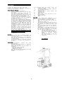
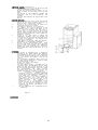
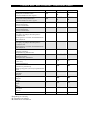
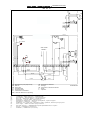
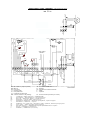
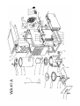
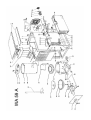
USER’S MANUAL
INSTRUKCJA OBSŁUGI
РУКОВОДСТВО ПО ПРИЕМЕНЕНИЮ
WA 41 A
WA 59 A
UNIVERSAL OIL HEATERS
NAGRZEWNICE NA OLEJ UNIWERSALNY
НАГРЕВАТЕЛИ НА УНИВЕРСАЛЬНОЕ
МАСЛО
Installation must be made in accordance with local regulations which may differ from this installation manual.
Montażu należy dokonać zgodnie z lokalnymi przepisami, które mogą się odbiegać od zaleceń w poniższej
instrukcji obsługi.
Сборку следует провести в согласии с местными законами, которые могут отличаться от этого
руководства.
CONTENTS
SPIS TREŚCI
СОДЕРЖАНИЕ
PAGE
STRONA
СТРАНИЦА
*
Description, warnings and installation
Opis, ostrzeżenia i montaż
Описание, предупреждения, сборка
*
Combustion chamber, ignition procedire and safeguards
Komora spalania, uruchamianie i zabezpieczenia
Камера сгорания, порядок запуска, предохранительные устройства
*
Maintenance, taking out of operation,
and draught test indicator
Konserwacja, wyłączanie i tester przewodu kominowego
поддержка, oкончание процесса и указатель проверки тяги
*
Drawing
Schemat urządzenia
Схема нагревателя
*
Spare parts list
Lista części zamiennych
Список запасных частей
*
Faults
Usuwanie usterek
Устранение неисправностей
*
Technical details
Dane techniczne
Технические данные
Electric wiring diagram
Schemat elektryczny
Электрическая схема
40.020.040
ENGLISH
To obtain full benefit from the WA 41 A and
trouble free operation, read the following
structions and information carefully.
* The
in1x
DESCRIPTION AND FUNCTION
*
The control panel incorporates a
switch, a locking device for the fuel and a
pilot light.
*
The electric pump motor drives the fuel
pump, which is positioned in the tank.
*
The fuel pump delivers fuel to the combustion dish and is controlled by means of
the button above the control panel,
At position low, the consumption is approx.
2,5 l/h. At position high, the consumption
is approx. 4,3 l/h.
One and another depends on viscosity.
*
The main fan is controlled by a thermostat.
As soon as the combustion chamber has warmed
up sufficiently, the fan starts to operate.
*
The burner is equipped with an air intake
fan to supply air for combustion. This air
combustion fan stops when the flame has
extinguished.
Pipes φ 200 mm can be
connected to this fan so that the combustion
air can be sucked from outside the area to
be heated.
*
Most types of waste oil can be used, such as
gearbox oil, gas oil, diesel oil, hydraulic
oil, HBO 1, 2 and 3, but not those with a
high viscosity, such as SAE90.
DO NOT USE TRANSFORMER OIL WHICH MIGHT
CONTAIN
SUBSTANCES
DETRIMENTAL
TO
THE
PERFORMANCE OF THE BURNER (PCB)
*
When the pump motor stops, the flame will
extinguish once the fuel in the burner dish
is exhausted.
WARNINGS
1
There could be a possible danger of
explosion if the burner is reignited while
it is still warm.
2
There must be sufficient air for combustion;
make sure that the combustion air intake fan
is never blocked.
3
Modifications made to the burner by dealer
or end user, invalidate the manufacturer's
warranty.
INSTALLATION
*
For
installation,
consult
the
local
prescriptions.
*
The burner must be installed on a completely
level, concrete floor.
*
Check that the chose position presents no
problem for:
- electrical supply 230V/2Amp.;
- flue pipe installation;
- combustion air supply.
*
Open the top cover of the burner and remove
the cover of the combsution
chamber.
-NLC-
1x
1x
1x
2x
1x
2x
1x
following
items
are
packed
within
the
combustion chamber:
T-piece with built-in draught stabiliser
for flue pipe connection
cleaning shovel
scraping tool to remove residue from
combustion dish
combustion dish
burner ring
spare card to seal the bottom of combustion chamber
handle with bolts
pedal
FLUE PIPE
For clean and trouble free combustion, it is
essential that the flue pipe is installed correctly.
a.
minimum diameter of flue pipe: 150mm
b.
check that flue connections are well sealed
c.
minimum flue height: 5 m
d.
the wind must be able to reach the top of
the flue from all directions (e.g.: it may
be necessary to extend flue above roof
apex)
e.
all pipes should be vertical if possible,
keep horizontal pipes to the absolute
minimum
f.
avoid bends in the flue installation if
possible but if unavoidable e.g. if flue
has two bends because of installation
through a wall or window, then:
1.
the pipe should be as high as
possible within the building
2.
flue pipe outside the building
should
be
insulated
(double
walled)
3.
the minimum height of the flue
has to be increased to 7.5 m to
compensate.
use a raincap
COMBUSTION CHAMBER (see figure 1)
*
Place burner ring (1) in the burner pot and
replace combustion chamber cover.
*
Unlock the sliding bottom drawer (2) by
means of pedal (3) and safety catch (6) and
open.
*
The bottom of the combustion chamber and
combustion dish are now accessible, see
figure 2.
Ignition and cleaning can now be dealt with
easily.
IGNITION PROCEDURE
1.
Fill the tank with fuel. Slide the locking
button on the control panel vertically to
open the tank, which hinges forward.
2.
Switch to "0"; connect plug to electricity
sypply and switch on at socket.
3.
Put capacity regulator in low position.
4.
Pour apporx. 1/3 litre of paraffin in the
combustion dish. Crumple some paper into a
ball, light it and drop into the dish to
ignite the oil. Close and lock the sliding
drawer. Check through the top cover that the
sealing around the bottom of the combustion
chamber is visible.
5.
Switch to "1". After about 5 minutes the
combustion
chamber
will
be
warmed
up
sufficiently for the main fan and pump motor
to come into operation. The orange pilot
light will illuminate.
6.
After approx. 30 minutes, make any necessary
adjustments to the draught stabiliser.
7.
During initial commissioning burn, there
will be some fumes from the heat resistant
paint finish and because the combustion
chamber has been oiled against corrosion.
These fumes will cease after about 30 to 40
minutes.
SAFEGUARDS
*
The burner is equipped with a thermostat
controlling the flame. Should the flame be
extinguished for any reason, this thermostat
will stop the fuel pump as well as the main
fan. For causes, see chapter "Location of
faults".
*
An overheating thermostat which shuts off
the fuel supply completely is reset by means
of a push button in the
burner. For causes, see chapter
"Location of faults".
*
The fuel supply system is equipped with an
"overflow tube", through which the oil flows
back into the tank incase the pipe to the
burner becomes obstructed. After the flame
has
extinguished,
the
flame
control
thermostat will switch off the burner. For
causes, see chapter "Location of faults".
*
The burner is equipped with an
"overflow security", located underneath
the bottom of the combustion chamber. This
will come into operation if, over a
period, the fuel is not burnt completely.
The excess fuel will flow from the
combustion dish, via an inlet tube, into a
small
container.
This
container
is
positioned
on
a
spring-loaded
micro
switch. As soon as this container is half
full, the fuel pump is switched off automatically. For causes, see chapter "Location of faults".
*
The air combustion fan is equipped with a
thermostat.
Figure 1
MAINTENANCE
-GBB-
The heater requires very little maintenance and the
regularity of such maintenance will depend greatly on
the type(s) of waste oil being burnt. The cleaner the
fuel, the less maintenance is required.
In general:
*
clean combustion dish and overflow tube daily;
*
clean burner pot, burner ring and combustion
chamber at least once a week. Ensure that the
air intake holes of combustion chamber and
lower side (3) at bottem connection are not
obstructed;
*
clean heat exchanger, fuel supply pipe, tank
and filter once per heating season;
*
combustion chamber bottom: as soon as the seal
around the bottom of the combustion chamber is
no longer visible, it is essential that it is
replaced, normally this is once per heating
season.
*
Clean filling sieve, fuel tank and filter
regularly.
*
The water in the tank can be drained by means
of a tap at the bottom of the tank.
TAKING OUT OF OPERATION
*
Switch to position "0". The fuel pump will
stop and the flame will be extinguished once
the oil in the combustion chamber is burnt.
*
Remove the plug from the wall socket after the
air intake fan has cooled down.
*
If the burner is not to be used for a long
period, combustion chamber, combustion dish,
heat exchanger and tank should be cleaned
carefully and protected against corrosion.
The heater is delivered with a spare seal. If this
seal is not replaced at the appropriate
time, leakages causing soot formation may occur. The
pedal assembly is equipped with an adjusting
screw (2).
If leakages occur or replacement of the seal is
necessary, adjust this screw so that the bottom of the
combustion chamber is set at more pres-sure against
the chamber.
┌────────────────────────────────────────────────┬─────────────────────────────────────────────────────────────┐
│
LOCATION OF FAULTS
│
│
├──────┬──────┬──────┬──────┬──────┬──────┬──────┤
│
│ A
│ B
│ C
│ D
│ E
│ F
│
│
│
├──────┼──────┼──────┼──────┼──────┼──────┼──────┤
│
│Flame │Flame │Soot │Heater│Heater│Over- │
│
│
│extin-│extin-│forma-│stops │heats │flow │
│
│
│
│gui- │gui- │tion │after │insuf-│secu- │
│
│shed │shes │in
│15 min│fi│rity │
│
CHECK:
│
│imme- │after │burner│or
│cient-│is
│
│
│
│diate-│the
│pot
│longer│ly
│filled│
│
A. Electrical connection.
│
│ly af-│main │and
│period│
│with │
│
B. Positioning of burner pan and burner ring.
│
│ter
│fan
│combus│
│
│oil
│
│
C. Flue installation, see page 1.
│
│
│
│
│
│
│igni- │has
│tion │
│tion │star- │cham- │
│
│
│
├─────────────────────┬───────────────────────────────────────┤
│
│ted
│ber
│
│
│
│
│
CAUSE
│
SOLUTION
│
├──────┼──────┼──────┼──────┼──────┼──────┼──────┼─────────────────────┼───────────────────────────────────────┤
│
│
1 │
│
7 │
5 │
│
│Fuel tank is empty or│ Clean filter.
│
│
│
│
│
│
│
│
│filter is obstructed.│
│
├──────┼──────┼──────┼──────┼──────┼──────┼──────┼─────────────────────┼───────────────────────────────────────┤
│
2 │
│
│
│
│Combustion air fan
│ Check: if plug is in socket.
│
│
2 │
│
│
│
│
│
│
│
│does not work.
│ Check: if fan motor is blocked.
│
│
│
│
│
│
│
│
│
│ Check: electrical connections and
│
│
│
│
│
│
│
│
│
│ thermostat.
│
│
│
│
│
│
│
│
│
│ Check: air supply to the fan.
│
├──────┼──────┼──────┼──────┼──────┼──────┼──────┼─────────────────────┼───────────────────────────────────────┤
│
3 │
│
5 │
3 │
│
│Supply tube is ob│ Fuel flows into tank via return pipe, │
│
│
│
│
│
│
│
│
│structed.
│ clean fuel supply tube.
│
├──────┼──────┼──────┼──────┼──────┼──────┼──────┼─────────────────────┼───────────────────────────────────────┤
│
│
4 │
│
4 │
│
│
│Pump motor is not
│ Check if pump shaft can be turned by │
│
│
│
│
│
│
│
│working.
│ hand. if not, remove and clean pump. │
│
│
│
│
│
│
│
│
│ Check if oil is too viscously: turn
│
│
│
│
│
│
│
│
│
│ capacity regulator to position high. │
│
│
│
│
│
│
│
│
│ Check overflow security switch by mo- │
│
│
│
│
│
│
│
│
│ ving the overflow tray a few times up │
│
│
│
│
│
│
│
│
│ and down.
│
│
│
│
│
│
│
│
│
│ Control switch is not pushed in or
│
│
│
│
│
│
│
│
│ drawn out well.
│
│
├──────┼──────┼──────┼──────┼──────┼──────┼──────┼─────────────────────┼───────────────────────────────────────┤
│
3 │
5 │
│
1 │
│
│
│Overheating security │ Too much oil has been used for the
│
│
│
│
│
│
│
│
│has switched off
│ ignition procedure.
│
│
│
│
│
│
│
│
│heater.
│ Check if main fan is not blocked and │
│
│
│
│
│
│
│
│(Reset this security │ working.
│
│
│
│
│
│
│
│
│by pushing the button│ Check fan and electric connections.
│
│
│
│
│
│
│
│
│in the heater)
│ Capacitor in switch box may be faulty.│
│
│
│
│
│
│
│
│
│ Overflow security is filled with oil, │
│
│
│
│
│
│
│
│
│ see F.
│
├──────┼──────┼──────┼──────┼──────┼──────┼──────┼─────────────────────┼───────────────────────────────────────┤
│
│
│
│
1 │
│
│
1 │
│Burner pan, burner
│ Clean burner pan daily.
│
│
│
│
│
│
│
│ring and burner pot │ Clean burner pot and burner ring at
│
│
│
│
│
│
│
│
│have not been cleaned│ least once a week.
│
│
│
│
│
│
│
│
│regularly.
│
│
├──────┼──────┼──────┼──────┼──────┼──────┼──────┼─────────────────────┼───────────────────────────────────────┤
│
│
│
4 │
│
│
│
│Poor connection be- │ Check packing and slide construction. │
│
│
│
│
│
│
│
│
│tween sliding panel │ Replace packing if necessary.
│
│
│
│
│
│
│
│with bottom and bur- │ Adjust set screw for spring pressure. │
│
│
│
│
│
│
│
│ner pot.
│
│
├──────┼──────┼──────┼──────┼──────┼──────┼──────┼─────────────────────┼───────────────────────────────────────┤
│
4 │
│
│
│
│
│
│Flame control thermo-│ Connect the two wires to the thermo- │
│
│
│
│
│
│
│
│stat is defective.
│ stat (attention, 220V) on nr. 5 and 12│
│
│ If main blower starts to rotate, this │
│
│
│
│
│
│
│
│
│
│
│
│
│
│
│
│ indicates a defective thermostat.
│
├──────┼──────┼──────┼──────┼──────┼──────┼──────┼─────────────────────┼───────────────────────────────────────┤
│
1 │
│
3 │
3 │
2 │
2 │
│Insufficient chimney │ Check flue for leakages.
│
│
│
│
│
│
│
│
│draught.
│ Check if draught stabiliser is in
│
│
│
│
│
│
│
│
│Min. draught = 2 mmwk│ closed position.
│
│
│
│ Check flue for obstruction.
│
│
│
│
│
│
│
│
│
│
│
│
│
│
│
│ Check flue height. Min. height is 5 m.│
│
│
│
│
│
│
│
│
│ If there is more than 1 elbow or hori-│
│
│
│
│
│
│
│
│
│ zontal pipe, the flue height must be │
│
│
│
│
│
│
│
│
│ extended.
│
├──────┼──────┼──────┼──────┼──────┼──────┼──────┼─────────────────────┼───────────────────────────────────────┤
1 │
3 │
│Fuel does not vapo- │ Viscosity of oil is too high. Mix with│
│
│
│
│
2 │
│
│
│
│
│
│
│
│rise sufficiently.
│ paraffin or diesel oil.
│
│
│
│
│
│
│
│
│After some time the │
│
│
│
│
│
│
│
│
│overflow security
│
│
│
│
│
│
│
│
│
│switches off heater. │
│
├──────┼──────┼──────┼──────┼──────┼──────┼──────┼─────────────────────┼───────────────────────────────────────┤
6 │
4 │
│
│Tank contains water. │ Clean tank. Drain by means of drain
│
│
│
2 │
│
│
│
│
│
│
│
│
│
│ plug beneath the tank.
│
└──────┴──────┴──────┴──────┴──────┴──────┴──────┴─────────────────────┴───────────────────────────────────────┘
Technical Data / Dane Techniczne / Технические данные
Capacity min. bruto
*
Wydajność minimalna brutto
Тепловая мощность мин. брутто
Capacity max. bruto
*
Wydajność maksymalna brutto
Тепловая мощность макс. брутто
Fuel Consumption min.
Zużycie paliwa min.
Расход топлива мин.
Fuel Consumption max.
Zużycie paliwa max.
Расход топлива макс
Burning duration with full tank min.
Czas pracy na pełnym zbiorniku paliwa –
wydajność min.
Время работы с полным топливным баком –
мин.мощность
Burning duration with full tank max.
Czas pracy na pełnym zbiorniku paliwa –
wydajność max.
Время работы с полным топливным баком –
мин.мощность
Heated Airflow
Przepływ powietrza
Нагретый воздушный поток
Voltage
Zasilanie sieciowe
Электрическое снабжение
Power Consumption
Pobór mocy
Потребляемый ток
Flue Diameter
Średnica rury kominowej
Диаметр патрубка для отвода отработанных
газов
Width
Szerokość
Ширина
Length
Długość
Длина
Weight
Waga
Вес
Height
Wysokość
Высота
* Depending on viscosity
* W zależności od lepkości
* В зависимости от вязкости
Jednostka
BTU/h
kW
WA 41 A
WA 59 A
82.000
24
123.000
36
BTU/h
kW
140.000
41
202.000
59
l/h
2,5
3,8
l/h
4,3
6,2
m3/h
3000
3000
V/Hz
220-240 / 50 220-240 / 50
A
1,1
1,2
mm
150
200
cm
820
820
cm
880
880
kg
135
175
cm
1.080
1.290
h
h
WIRING DIAGRAM / SCHEMAT ELEKTRYCZNY / ЭЛЕКТРИЧЕСКАЯ СХЕМА
BLUE
BROWN
BLACK
WA 41 A
(remove C!)
MBc
BROWN
BLUE
CB
11
12
BROWN
10
PM
PT
BROWN
BROWN
YELLOW
YELLOW
BLACK
LT
PL - yellow
VT
230V / 50Hz
SUPPLY
MS
BLUE
BROWN
BROWN
BLUE
BROWN
BROWN
BLACK
BLACK
OP
BLACK
BLACK
BROWN
BLUE
BLUE
6
7
8
9
10
11
12
1
2
YELLOW
GREEN
3
4
5
6
7
8
10
BLUE
BROWN
ORANGE
5
2
BLACK
S
FL
MS
MB
PM
LT
T
CB
PL
OS
S
C
12
4
1
MS : Microswitch for pump stop security
MB : Main fan
PM : Pump motor
LT : Limit thermostat
PT : Pump thermostat
VT : Combustion air thermostat
MBc : Main fan radial for C-kit (Ancillary)
11
BROWN
RED
PURPLE
9
YELLOW
5
BROWN
4
YELLOW
3
CB
GREEN
2
WHITE
1
MB
CB : Combustion air intake fan
PL : Pilot light
OP : microswitch for Overflow Protection
S : Switch
C : Capacitor
Flashlight /Lamka kontrolna / Сигнальный свет
Microswitch / Mikrowyłącznik / Микропереключатель
Main fan / Wentylator główny / Главный вентилятор
Pump motor / Silnik pompy / Двигатель насоса
Overheating thermostat / Termostat przegrzania /Термостат перегрева
Thermostat / Termostat / Термостат
Combustion air intake fan / Wentylator komory spalania /Вентилятор камеры сгорания
Pilot light / Lamka kontrolna /Контрольный свет
Overflow security / Zabezpieczenie przed przelewem / Защита от перелива
Switch / Przełącznik / Переключатель
Condensor / Kondensator /Конденсатор
C
40.020.674/02
WIRING DIAGRAM / SCHEMAT ELEKTRYCZNY / ЭЛЕКТРИЧЕСКАЯ СХЕМА
BLUE
BROWN
BLACK
WA 59 A
(remove C!)
MBc
BROWN
BLUE
CB
11
12
BROWN
10
LOW
BROWN
RED
PT
LT
RED
VT
230V / 50Hz
SUPPLY
MS
10
BROWN
RT
BLUE
BROWN
BROWN
OP
11
BLUE
BLACK
BLACK
PL - red
BLACK
BLACK
BLACK
BLACK
PL - yellow
BROWN
YELLOW
YELLOW
PM
BROWN
BLACK
HIGH
BROWN
12
BLUE
BLUE
6
7
8
9
10
11
1
12
2
3
4
5
6
7
8
9
10
BROWN
YELLOW
GREEN
BLUE
12
BROWN
WHITE
RED
GREY
4
1
PURPLE
11
2
3
YELLOW
5
BROWN
4
YELLOW
3
CB
GREEN
2
WHITE
1
MB
S
5
BLACK
C
6
ORANGE
MS : Microswitch for pump stop security
MB : Main fan
PM : Pump motor
LT : Limit thermostat
PT : Pump thermostat
VT : Combustion air thermostat
CB : Combustion air intake fan
PL : Pilot light
OP : microswitch for Overflow Protection
S : Switch
C : Capacitor
MBc : Main fan radial for C-kit (Ancillary)
RT : Room thermostat (Accessory for AT-500)
FL
Flashlight /Lamka kontrolna / Сигнальный свет
MS
Microswitch / Mikrowyłącznik / Микропереключатель
MB
Main fan / Wentylator główny / Главный вентилятор
PM
Pump motor / Silnik pompy / Двигатель насоса
LT
Overheating thermostat / Termostat przegrzania /Термостат перегрева
T
Thermostat / Termostat / Термостат
CB
Combustion air intake fan / Wentylator komory spalania /Вентилятор камеры сгорания
PL
Pilot light / Lamka kontrolna /Контрольный свет
OS
Overflow security / Zabezpieczenie przed przelewem / Защита от перелива
S
Switch / Przełącznik / Переключатель
C
Condensor / Kondensator /Конденсатор
40.020.592/03
UNIVERSAL OIL HEATERS – WA 41
Pos.
Code NR
1
2
3
4
5
6
7
8
9
10
11
12
13
14
15
16
17
18
18a
19
20
21
22
23
24
25
26
27
28
29
30
31
32
33
34
35
36
37
38
39
40
41
42
43
44
45
46
47
48
49
49a
50
51
52
53
54
55
56
57
58
59
60
61
S/R
S/R
S/R
S/R
S/R
S/R
S/R
S/R
S/R
S/R
S/R
4506.137
S/R
4506.141
S/R
4506.138
4506.021
4506.043
4506.044
4506.133
4506.136
4506.130
4506.125
4506.140
4506.019
4506.020
4506.126
S/R
4506.006
S/R
4506.005
4506.123
4506.134
S/R
S/R
4506.131
4506.118
4506.122
4506.003
4506.121
N/A
S/R
S/R
4506.119
S/R
S/R
S/R
4506.135
4506.116
4506.139
4506.132
4506.117
4506.202
4506.124
4506.128
4506.120
4506.129
S/R
4506.002
4506.115
4506.127
S/R
S/R
Description
SIDE PLATE LEFT
SIDE PLATE RIGHT
BACK PANEL
COOLING PLATE
SLIDING PANEL
BOTTOM PANEL
TOP LID
FRAME
SIDE PANEL LEFT
SIDE PANEL RIGHT
TOP LID OF CONTROL PANEL
TANK
BLOWING GRILL
VAPORIZING SECTION
SLIDER
BOTTOM
COMBUSTION DISH
BURNER RING
HEAT SHIELD WA 41A
BAFFLE PLATE
COMBUSTION CHAMBER
COVER COMBUSTION CHAMBER
LOCKING BAR
HEAT EXCHANGER
THERMOSTAT
OVERHEAT THERMOSTAT
LEVER
LOCKING DEVICE
FUEL PUMP
FUEL PUMP SUPPORT
FILTER
DRIVE SHAFT
FUEL TANK FILTER
3-WAY CONNECTOR
SUPPLY PIPE
CONNECTOR
DRIP FEED PIPE
RETURN LINE
PUMP MOTOR
SWITCH
PILOT LIGHT RED
CONTROL PANEL
AIR INLET PLATE
CAPACITOR
FAN HOUSING
MOTOR CLIP
PROTECTION GRILL
MOTOR
COMBUSTION FAN
MAIN FAN
PROTECTION GRILL
PILOT LIGHT YELLOW
MICRO SWITCH
OVERFLOW TRAY
COMPRESION SPRING
SEALING CORD
SEALING CORD
THERMOSTAT BRACKET
T-PIECE
CROWN STRIP
COOLING PLATE
MICRO SWITCH PUMP STOP
SHOWEL
S/R – Parts available by special request only
4
UNIVERSAL OIL HEATERS – WA 59
Pos.
Code NR
1
2
3
4
5
6
7
8
9
10
11
12
13
14
15
16
17
18
19
20
21
22
23
24
25
26
27
28
29
30
31
32
33
34
35
36
37
38
39
40
41
42
43
44
45
46
47
48
49
49a
50
51
52
53
54
55
56
57
58
59
60
61
S/R
S/R
S/R
S/R
S/R
S/R
S/R
S/R
S/R
S/R
S/R
4506.137
S/R
4506.148
S/R
4506.138
4506.021
4506.149
4506.133
4506.145
4506.130
4506.125
4506.147
4506.019
4506.020
4506.126
S/R
4506.143
S/R
4506.005
4506.123
4506.134
S/R
S/R
4506.131
4506.118
4506.122
4506.004
4506.058
N/A
S/R
S/R
4506.119
S/R
S/R
S/R
4506.135
4506.116
4506.139
4506.132
4506.117
4506.202
4506.124
4506.128
4506.120
4506.129
S/R
4506.144
4506.115
4506.127
S/R
S/R
Description
SIDE PLATE LEFT
SIDE PLATE RIGHT
BACK PANEL
COOLING PLATE
SLIDING PANEL
BOTTOM PANEL
TOP LID
FRAME
SIDE PANEL LEFT
SIDE PANEL RIGHT
TOP LID OF CONTROL PANEL
TANK
BLOWING GRILL
VAPORIZING SECTION
SLIDER
BOTTOM
COMBUSTION DISH
BURNER RING
BAFFLE PLATE
COMBUSTION CHAMBER
COVER COMBUSTION CHAMBER
LOCKING BAR
HEAT EXCHANGER
THERMOSTAT
OVERHEAT THERMOSTAT
LEVER
LOCKING DEVICE
FUEL PUMP
FUEL PUMP SUPPORT
FILTER
DRIVE SHAFT
FUEL TANK FILTER
3-WAY CONNECTOR
SUPPLY PIPE
CONNECTOR
DRIP FEED PIPE
RETURN LINE
PUMP MOTOR
SWITCH
PILOT LIGHT RED
CONTROL PANEL
AIR INLET PLATE
CAPACITOR
FAN HOUSING
MOTOR CLIP
PROTECTION GRILL
MOTOR
COMBUSTION FAN
MAIN FAN
GRILL
PILOT LIGHT YELLOW
MICRO SWITCH
OVERFLOW TRAY
COMPRESION SPRING
SEALING CORD
SEALING CORD
THERMOSTAT BRACKET
T-PIECE
CROWN STRIP
COOLING PLATE
MICRO SWITCH PUMP STOP
SHOWEL
S/R – Parts available by special request only
6