1
Model PMD690 User Guide
Portable PC Card Recorder
CAUTION
RISK OF ELECTRIC SHOCK
DO NOT OPEN
CAUTION: TO REDUCE THE RISK OF ELECTRIC SHOCK,
DO NOT REMOVE COVER (OR BACK)
NO USER-SERVICEABLE PARTS INSIDE
REFER SERVICING TO QUALIFIED SERVICE PERSONNEL
The lightning flash with arrowhead symbol, within
an equilateral triangle, is intended to alert the user
to the presence of uninsulated “dangerous voltage”
within the product’s enclosure that may be of sufficient magnitude to constitute a risk of electric shock
to persons.
The exclamation point within an equilateral triangle
is intended to alert the user to the presence of
important operating and maintenance (servicing)
instructions in the literature accompanying the
appliance.
WARNING
TO REDUCE THE RISK OF FIRE OR ELECTRIC SHOCK,
DO NOT EXPOSE THIS APPLIANCE TO RAIN OR MOISTURE.
CAUTION: TO PREVENT ELECTRIC SHOCK, MATCH WIDE
BLADE OF PLUG TO WIDE SLOT, FULLY INSERT.
ATTENTION: POUR ÉVITER LES CHOCS ÉLECTRIQUES,
INTRODUIRE LA LAME LA PLUS LARGE DE LA FICHE DANS LA
BORNE CORRESPON-DANTE DE LA PRISE ET POUSSER
JUSQU’AU FOND.
SAFETY
INSTRUCTIONS
READ BEFORE OPERATING EQUIPMENT
This product was designed and manufactured to meet strict
quality and safety standards. There are, however, some installation and operation precautions which you should be
particularly aware of.
12. Grounding or Polarization — The precautions that
should be taken so that the grounding or polarization
means of an appliance is not defeated.
1. Read Instructions — All the safety and operating instructions should be read before the appliance is operated.
2. Retain Instructions — The safety and operating instructions should be retained for future reference.
3. Heed Warnings — All warnings on the appliance and in
the operating instructions should be adhered to.
4. Follow Instructions — All operating and use instructions
should be followed.
5. Water and Moisture — The appliance should not be
used near water — for example, near a bathtub, washbowl, kitchen sink, laundry tub, in a wet basement, or
near a swimming pool, etc.
6. Carts and Stands — The appliance should be used only
with a cart or stand that is recommended by the manufacturer.
7. An appliance and cart combination should be moved
with care. Quick stops, excessive force, and uneven
surfaces may cause the appliance and cart combination to overturn.
AC POLARIZED PLUG
13. Power-Cord Protection — Power-supply cords should
be routed so that they are not likely to be walked on or
pinched by items placed upon or against them, paying
particular attention to cords at plugs, convenience receptacles, and the point where they exit from the
appliance.
14. Cleaning — The appliance should be cleaned only as
recommended by the manufacturer.
15. Power Lines— An outdoor antenna should be located
away from power lines.
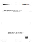
16. Outdoor Antenna Grounding — If an outside antenna is
connected to the receiver, be sure the antenna system
is grounded so as to provide some protection against
voltage surges and built up static charges. Section 810
of the National Electrical Code, ANSI/NFPA No. 701984, provides information with respect to proper
grounding of the mast and supporting structure,
grounding of the lead-in wire to an antenna discharge
unit, size of grounding conductors, location of antennadischarge unit, connection to grounding electrodes, and
requirements for the grounding electrode. See Fig. 1.
17. Nonuse Periods — The power cord of the appliance
should be unplugged from the outlet when left unused
for a long period of time.
8. Wall or Ceiling Mounting — The appliance should be
mounted to a wall or ceiling only as recommended by
the manufacturer.
18. Object and Liquid Entry — Care should be taken so that
objects do not fall and liquids are not spilled into the enclosure through openings.
9. Ventilation — The appliance should be situated so that
its location or position does not interfere with its proper
ventilation. For example, the appliance should not be
situated on a bed, sofa, rug, or similar surface that may
block the ventilation openings; or, placed in a built-in
installation, such as a bookcase or cabinet that may
impede the flow of air through the ventilation openings.
19. Damage Requiring Service — The appliance should be
serviced by qualified service personnel when:
10. Heat — The appliance should be situated away from
heat sources such as radiators, heat registers, stoves,
or other appliances (including amplifiers) that produce
heat.
11. Power Sources — The appliance should be connected
to a power supply only of the type described in the operating instructions or as marked on the appliance.
A. The power-supply cord or the plug has been damaged; or
B. Objects have fallen, or liquid has spilled into the appliance; or
C. The appliance has been exposed to rain; or
D. The appliance does not appear to operate normally
or exhibits a marked change in performance; or
E. The appliance has been dropped, or the enclosure
damaged.
20. Servicing — The user should not attempt to service the
appliance beyond that described in the operating instructions. All other servicing should be referred to
qualified service personnel.
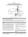
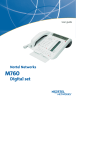
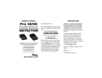
FIGURE 1
EXAMPLE OF ANTENNA GROUNDING ACCORDING TO
NATIONAL ELECTRICAL CODE INSTRUCYIONS
CONTAINED IN ARTICLE 810 -"RADIO AND TELEVISION EQUIPMENT"
ANTENNA LEAD
IN WIRE
GROUND CLAMP
ANTENNA
DISCHARGE UNIT
(NEC SECTION 810-20)
ELECTRIC
SERVICE
EQUIPMENT
GROUNDING CONDUCTORS
(NEC SECTION 810-21)
GROUND CLAMPS
POWER SERVICE GROUNDING
ELECTRODE SYSTEM
(NEC ART 250, PART H)
NEC - NATIONAL ELECTRICAL CODE
NOTE TO CATV SYSTEM INSTALLER:
This reminder is provided to call the CATV (Cable-TV) system installer's attention to Article 820-40 of the NEC,
which provides guidelines for proper grounding and, in particular, specifies that the cable ground shall be
connected to the grounding system of the building, as close to the point of cable entry as practical.
NOTE:
This equipment has been tested and found to comply
with the limits for a Class B digital device, pursuant to
Part 15 of the FCC Rules. These limits are designed
to provide reasonable protection against harmful interference in a residential installation. This equipment
generates, uses and can radiate radio frequency energy and, if not installed and used in accordance with
the instructions, may cause harmful interference to
radio communications. However, there is no guarantee that interference will not occur in a particular
installation. If this equipment does cause harmful
interference to radio or television reception, which can
be determined by turning the equipment off and on,
the user is encouraged to try to correct the interference by one or more of the following measures:
– Reorient or relocate the receiving antenna.
– Increase the separation between the equipment
and receiver.
– Connect the equipment into an outlet on a circuit
different from that to which the receiver is connected.
– Consult the dealer or an experienced radio/TV
technician for help.
This Class B digital apparatus complies
with Canadian ICES-003.
Cet appareil numérique de la Classe B est
conforme à la norme NMB-003 du Canada.
NOTE:Changes or modifications may cause this
unit to fail to comply with Part 15 of the FCC Rules
and may void the user's authority to operate the
equipment.
SETTING UP
Thank you for your purchase of the Marantz Professional
PMD690 PC Card Recorder. The PMD690 is the next
generation of portable digital recorders that bridge the
gap between real-time audio recording and computers —
while keeping the size and functionality of our renowned
portable cassette and MiniDisc recorders.
The PMD690 has been designed as a field acquisition tool.
This means that the unit itself is designed to record audio
in a computer compatible file format. The audio files are
then meant to be transferred to a computer for editing or
transmission.
The recording medium of the PMD690, PCMCIA
compatible PC Cards, allows plug-and-play compatibility
with desktop and laptop computers. Flash PC Cards are
based on flash memory technology that features no
moving parts and is not affected by movement and
temperature. Flash memory cards are available through
most computer and digital photography products
resellers. For a complete list of approved cards for the
PMD690, please refer to the Marantz Professional website
at www.marantz.com.
The MP2 (MPEG1 layer2) file format that is supported by
the PMD690 is a worldwide standard for compressed
digital audio storage and transmission. Many playback
and editing systems are available commercially and
through the Internet. For more information on MP2 based
playback and editing systems, please consult your dealer.
Also supported by the PMD690, PCM (Pulse Code
Modulation) is the most widely used format for coding
uncompressed digital audio. The PCM system is used on
CD players, DAT recorders, and on computer editing
programs that support Wave (.wav) files. Recording in
the PCM format will provide the most universally
accepted storage format but comes with the limitation that
it uses a lot of memory very quickly.
USING THIS MANUAL
Please read these operating instructions carefully. We
recommend that you read the entire user guide before you
connect or operate the unit.
After you have reviewed the contents this manual, we
suggest that you make all system connections before you
attempt to operate the unit.
FOREWORD
This section must be read before any connection is made
to the mains supply.
WARNINGS
Do not expose the equipment to rain or moisture.
Do not remove the cover from the equipment.
COPYRIGHT
Recording and playback of any material may require
consent. For further information refer to the following:
–
–
–
–
Copyright Act 1956
Dramatic and Musical Performers Act 1958
Performers Protection Acts 1963 and 1972
any subsequent statutory enactments and orders
PRECAUTIONS
The following precautions should be considered when
operating the equipment.
When setting the equipment ensure that :
ENGLISH
INTRODUCTION
– the equipment will not be exposed to interference from an
external source
– the equipment will not be exposed to excessive heat, cold,
moisture or dust
– the equipment will not be exposed to direct sunlight
– the equipment will not be exposed to electrostatic discharges
• In addition, never place heavy objects on the equipment.
• If a foreign object or water does enter the equipment, contact
your nearest dealer or service center.
Features
• Stereo (2 channels) and monaural (1 channel) audio
recording and playback
• Recording onto various types of approved PC Cards
– Please refer to the Marantz Professional website at
www.marantz.com for the complete list of approved
cards
• Two different recording formats:
– Compressed recording using MPEG1 Layer2 (MP2),
mono and stereo
– Uncompressed recording using 16-bit/48kHz Pulse
Code Modulation (PCM)
• MS-DOSTM and Windows compatible file system
• Selectable file types:
– Wave (.wav)
– Broadcast Wave (.bwf)
– Raw MP2 (.mp2)
• Manual, manual with limiter, and automatic (ALC)
record level control
• An ANC (Ambient Noise Cancel) switch for reducing
unwanted background noises
• Pre-Recording memory buffer that records 2 seconds
prior to when recording is started
• Portions of multiple recordings can be played back in
sequence using the EDL (Edit Decision List) system
• Three different ways to power the unit:
– Included AC adaptor
– 8 Alkaline AA batteries
– Optional rechargeable Ni-Cad battery pack
• Built-in Time and Date generator marks each recording
• Remote input for pausing and un-pausing during
recording or playback
Do not push anything inside the equipment through the
ventilation holes.
1
SETTING UP
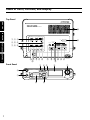
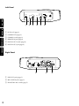
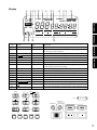
How to Use this Manual
This manual is divided into the 7 sections described
below. To find out how to use a specific control, refer to
the section "Index of Parts, Controls, and Display" on page
1– 4.
ENGLISH
SETTING UP
This section describes how to set up the unit in
preparation for recording and playback.
PRESET MENU
This section provides information about the various preset
menu options.
GENERAL FUNCTIONS
This section provides information about the functions and
operations that are common for recording and playback.
Contents
SETTING UP
AC Adaptor and Batteries ........................................................ 3
Power On/Off ............................................................................. 4
Setting the Date and Time ........................................................ 4
Understanding PC Card ........................................................... 5
Capacity of Files and Card ....................................................... 6
Connecting Microphones .......................................................... 7
Connecting Analog Components ............................................ 7
Connecting Digital Components ............................................. 8
Other Connections ..................................................................... 8
PRESET MENU
Preset Items .................................................................................. 9
Recording Time ........................................................................... 9
Preset Operation ......................................................................... 9
GENERAL FUNCTIONS
RECORDING
This section describes the various input controls, record
settings, and the basic recording procedure.
PLAYBACK AND EDITING
This section describes the basic playback procedure and
options, and details the editing options availble to
recorded tracks.
THE EDL
This section describes the EDL (Edit Decision List) system
and how to configure and manipulate EDL marks in a
recording to create a custom playback sequence.
Low Battery Warning and Auto Power Off ........................ 12
Display Selections .................................................................... 12
Display Backlight ..................................................................... 13
Key (Button) Lock .................................................................... 13
RECORDING
Input Controls ........................................................................... 14
Record Settings ......................................................................... 15
Recording Operation ............................................................... 16
PLAYBACK and EDITING
Playback ..................................................................................... 18
Auto Power Off ......................................................................... 19
Track Editing ............................................................................. 19
ADDITIONAL INFORMATION
THE EDL
This section includes detailed information about error
handling, the PC Card recording system, troubleshooting,
specifications, and the "Index of Parts, Controls, and
Display", which allows you to look up operations of
specific controls.
EDL Marking ............................................................................. 21
Searching for EDL Marks ....................................................... 22
Editing EDL Marks .................................................................. 23
EDL Playback ............................................................................ 24
ADDITIONAL INFORMATION
Error Messages .......................................................................... 26
File Structure ............................................................................. 26
Troubleshooting ........................................................................ 27
Care and Maintenance ............................................................. 27
Specifications ............................................................................. 28
Index of Parts, Controls, and Display ........................... 1~4
2
SETTING UP
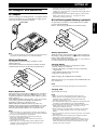
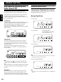
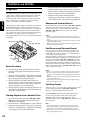
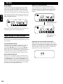
AC Adaptor
When recording for extended periods, or using this unit in
a fixed environment, it is recommended to supply power
to the unit via the included AC adaptor.
to AC outlet
Note
• It is recommended to only use the Marantz Professional brand
AC adaptor (model DA600) for use with the PMD690.
Alkaline Batteries
The PMD690 can operate using 8 standard AA size
alkaline batteries.
First load the batteries into the battery holder and then
load the holder as shown in the following illustration.
Ni-Cad Rechargeable Battery (optional)
An optional Ni-Cad battery (model RB1100) is available
for use with the PMD690.
Refer to the following illustration to load the battery.
ENGLISH
AC Adaptor and Batteries
• If batteries leak, dispose of them immediately. Avoid touching
the leaking material or letting it come into contact with
clothing, etc. Clean the battery compartment thoroughly before
installing new batteries.
• For optimum life and accurate battery display, make sure the
battery ("bat") preset is set to "al". See page 9 for more
information on the preset menu.
Battery Replacement
When the battery alert indicator (
) appears steadily in
the display, charge the battery or replace the rechargeable
battery with a fully charged one.
A fully charged battery should provide 1-1/2 to 2 hours of
record or playback time (backlight off).
Charging Battery
The optional Ni-Cad battery is charged only when:
• The AC adaptor is connected
• The Ni-Cad battery is loaded correctly in the battery
compartment
• The CHARGE slide switch is set to ON
• The power to the unit is off
While charging, the CHARGE LED will blink.
When the charge cycle is complete, the CHARGE LED will
stay steadily on.
Notes
• The battery will not charge when the power to the unit is on.
Battery Replacement
When the battery alert indicator (
) appears steadily in
the display, replace all batteries with new ones. For the
complete description of the battery alert indiactor, please
refer to page 12.
Fresh alkaline batteries will provide 1-1/2 to 2-1/2 hours
of record or playback time (display backlight off)
depending on the type of batteries used.
Different brands of alkaline batteries provide very
different levels of performance in the PMD690. For a list
of the best performing alkaline batteries please see the
Marantz Professional website at www.marantz.com.
Notes
• When recording, to avoid problems caused by loss of battery
power, it is recommended to always use new alkaline batteries.
• Use only AA size batteries for replacement.
• Be sure to insert the batteries with correct polarity (as
illustrated on the battery holder).
• Remove the batteries if the unit will not be used for an
extended period of time.
• Battery life may vary depending on the conditions under
which the unit is operated (environmental temperature,
humidity, speaker usage, etc.).
Charging Time
Approximately 3 hours.
Notes
• Make sure to fully charge the battery before first use.
• Battery life may vary depending on the conditions under
which the unit is operated (environmental temperature,
humidity, speaker usage, etc.).
• It is recommended to only use the Marantz Professional brand
AC adaptor (model DA600) for use with the PMD690.
• For optimum life and accurate battery display, make sure the
battery ("bat") preset is set to "nc". See page 9 for more
information on the preset menu.
• When recording, to avoid problems caused by loss of battery
power, it is recommended to always use a fully charged
battery.
• Remove the battery if the unit will not be used for an extended
period of time.
• If the charge LED does not blink when charging should be
taking place, remove and then restore power.
• The battery power should be completely used before it is recharged because Ni-Cad type batteries have a memory effect
which will reduce the total power of the battery if it is only
partially used and re-charged.
3
SETTING UP
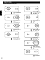
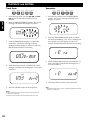
Power On/Off
Setting the Date and Time
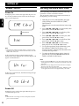
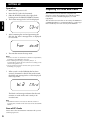
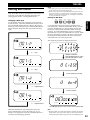
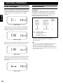
Power On
Sliding the power switch to the right turns the power on.
If a correctly formatted card is in the slot, the messages
below will be displayed.
Before operating your PMD690, perform the following
operations to set the current date and time.
The current date and time are recorded automatically at
the beginning of each recording.
ENGLISH
1
2
3
Card Check
4
5
OVER
6
7
Note
• TOC stands for Table of Contents and it is a reference to the
beggining of the card that contains the information on all the
audio tracks on the card.
If the card in the slot has not been formatted to the
specifications of the PMD690, the Un-Format display will
appear as indiacted below:
8
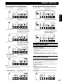
With the power off, slide POWER to the right
while holding down the DISPLAY (TIME/
DATE) button.
The unit turns on and enters the date/time setup
mode.
Press 1˜4 or ¢˜¡ to set the month, then
press PLAY/PAUSE (3˜8) to enter.
Press 1˜4 or ¢˜¡ to set the day, then
press PLAY/PAUSE (3˜8) to enter.
Press 1˜4 or ¢˜¡ to set the year, then
press PLAY/PAUSE (3˜8) to enter.
Press 1˜4 or ¢˜¡ to set the hour, then
press PLAY/PAUSE (3˜8) to enter.
Press 1˜4 or ¢˜¡ to set the minute,
then press PLAY/PAUSE (3˜8) to enter.
To save the input time/date information, press
the DISPLAY (TIME/DATE) button. The
seconds will start counting from 00 and the unit
will enter the stop mode.
To return to the date setting display (step #2),
press the PLAY/PAUSE (3˜8) instead of the
DISPLAY (TIME/DATE) button.
Notes
• Pressing the STOP (7) button at any time during the time/date
setting mode will cancel any changes and return the unit to the
stop mode.
• The time is always displayed in 24-hour time. So for example,
23:59:59 is equivalent to 11:59:59 PM.
• The clock runs on an internal large capacitor. While the power
is not applied, the clock runs for approximately one month.
If there is no card in the slot, then the following message
will be displayed:
Power Off
Sliding the power switch to the right while the power is
on will turn the power off.
Note
• While the unit is recording or in the record-pause mode, the
power switch is disabled.
4
SETTING UP
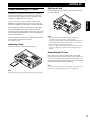
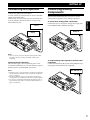
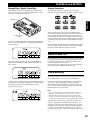
Understanding PC Cards
Ejecting a Card
Push the EJECT button as indicated to eject the PC Card
from the PMD690.
The PMD690 records digital audio directly to PCMCIA
and ATA compatable PC Cards. The PC Card storage
system allows direct plug-and-play compatibility with
conputers equipped with a PC Card slot.
Even though most PCMCIA compatible PC Card can be
read by the PMD690, only certain types of cards can
sustain the record speeds required. Therefore, only cards
tested and approved by Marantz Professional should be
used with the PMD690.
The recommended card list for the PMD690 can be found
on the Marantz Professional website at
www.marantz.com.
Inserting a Card
Push the PC Card into the PMD690 as follows.
ENGLISH
PC Cards come in a variety of shapes and sizes. The
PMD690 is compatible with all types as long as they are
PCMCIA compatible (flash memory and hard disk cards).
PUSH
Notes
• The EJECT button is mechanical and ejects the PC Card
regardless of the unit’s power or operating status.
Do not press EJECT while recording (when the REC indicator
is lit). Though a secure file storage scheme is used, this may
result in the loss of all data on the PC Card.
• Also do not eject the card when the unit is checking the card
("CHE card" display) or when the TOC is being read ("toc"
display).
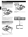
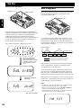
Formatting a PC Card
Before using a PC Card for the first time, perform the
following operations to format the PC Card so that it can
be used to record audio. This operation completely erases
any information stored on the card. Be sure to backup any
important information before formatting.
Note
You can also use this operation to completely erase a previously
used PC Card containing audio data you no longer need.
Note
• Make sure the card is inserted with the correct side facing up.
5
SETTING UP
Operation
1
2
3
4
Make sure the power is off.
Insert the PC Card to be formatted.
Slide the POWER switch to the right while
holding down the ERASE (FORMAT) button.
The format message below will be displayed.
ENGLISH
OVER
5
After formatting the card and generating the
EDL file, the "done" message below is displayed
for 3 seconds.
OVER
6
The unit then enters the stop mode
Notes
• Even if a PC Card was formatted in a Windows compatible PC,
formatting by the PMD690 is neccessary.
• After recording and erasing a card many times, it is
recommended to format the card so that new recording can be
stored in the optimum way.
• Do not eject the PC Card or turn this unit’s power off while
formatting is in progress.
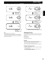
7
When a card is in the PMD690 that has been
correctly formatted or had all the tracks erased,
the blank card message below will be displayed
in the stop mode.
The blank card message indicates that the card
contains no audio tracks and is ready to be
recorded onto.
Note
• The DISPLAY button can be used to check the amount of
recording time available on the card based on the selected REC
MODE.
Care of PC Cards
Please refer to the documentation included with your PC
card for proper care.
6
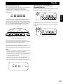
Capacity of Files and Card
Due to limitations in the MS-DOS compatable file
structure system, the maximum size of all the recorded
tracks on a card is 1,200MB (MegaBytes) or 1.2GB
(GigaBytes).
The maximum card size that can be read by the PMD690 is
2,150MB (MegaBytes) or 2.15GB (GigaBytes). Cards larger
than 2.15GB may not work correctly in the PMD690.
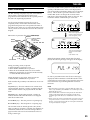
SETTING UP
Connect microphones as shown below.
You can connect two microphones for stereo to the MIC/
LINE L and R (XLR) jacks.
Alternatively, you can connect just one microphone (for
mono recording or dual level mono recording) to the
MIC/LINE IN L jack.
MIC (L)
Connecting Analog
Components
The following illustrations show you how to connect
analog audio components for recording or playback.
To record from analog audio components
Connect the source component’s analog line output jacks
to the PMD690's MIC/LINE IN (XLR) jack.
ENGLISH
Connecting Microphones
MIXER, etc.
MIC (R)
LINE OUT
R
R
L
L
Notes
• Take care not to connect or disconnect microphones while
recording. This may result in unwanted sounds in the
recording.
Powering the microphone(s)
This unit can supply +48 V of phantom power to the
connected microphone(s). If your microphone(s) require
phantom power, set PHANTOM +48V to ON.
Notes
• Phantom power is only applicable to condenser microphones.
See the instruction manual of your microphones if phantom
power is required.
• Do not use phantom power in combination with dynamic
microphones to avoid damage to the unit or the microphones.
• You can also compensate for different microphones and/or
environments. (See “ANC” and “MIC ATTENUATION” on
page 14 for details.)
To output analog audio signals to another audio
component
Connect the LINE OUT (RCA) jack on the PMD690 to the
analog input on the destination component.
MIXER, TAPE DECK, etc.
LINE IN
R
L
7
SETTING UP
Connecting Digital Components
The following illustrations show you how to connect
digital audio components.
Remote Control
Contact closure
switch
ENGLISH
To output digital audio signals to another audio
component
Connect the DIGITAL OUT (RCA) jack on the PMD690 to
the digital input jack on the destination component. Turn
the output on by placing the switch (next to the output
jack) in the ON position.
DAT, etc.
DIGITAL IN
Available Functions
The remote Pauses or Un-Pauses the unit during playback
and recording.
Notes
• Digital audio is only output during normal playback and EDL
playback. Digital audio is not output during recording even if
the output is turned on.
• When the digital output is not used, make sure to keep the
DIGITAL OUT switch OFF to save battery life.
• Make sure the destination component accepts the SPDIF (or
IEC-958-II) type digital audio format.
• Make sure the destination component accepts a sampling
frequency of 48kHz or contains a digital sample rate converter.
Polarity of the REMOTE jack
Open
Close
Recording
Pause recording
Resume recording
Playback
Resume playback
Pause playback
REMOTE
Other Connections
Headphones
Connect headphones to the HEADPHONE output as
indicated below. Both recording and playback can be
monitored through connected headphones.
Notes
• Use the HP/SPK VOLUME knob to control the volume of the
headphone.
• The sound from the internal speaker is muted automatically
when headphones are connected.
8
2.5 mm Jack
PRESET MENU
Preset Items
Preset Operation
The preset menu of the PMD690 allows many features and
functions of the unit to be customized for individual
requirements.
AUTO MARK
PRESET
1/4 ¢/¡
Preset
Display Available Options
Bit rate of STEREO SP br
Default
Setting
PCM: 1536 kbps (PC2)
MPEG: 384, 256 kbps
1)
Bit rate of STEREO LP br
MPEG: 192, 128, 96, 64 kbps 1)
128 kbps
Bit rate of MONO br
PCM:768 kbps (PC1) 1),
64 kbps
MPEG: 192, 128, 96, 64, 48, 32 kbps 1)
Sound level for silent skip SL
-50dB to -10dB, 5dB step
-40 dB
Silent time for silent skip St
1 to 5 second
3 seconds
Alarm beep
aLa
on, off
Battery type
bat
Alkaline, Ni-Cad, Ni-MH,
File format
For
on
Alkaline
3)
Wave (.wav) , MP2 (.mp2), MP2
Broadcast Wave (.bwf)
ID1,2,3
Id1
000000 to 999999
000000
Id2
Id3
Note 1)
Please refer to the following section.
Note 2)
On/off for alarm beep at auto power off and for low battery
warning.
See page 12 "Low Battery Warning and Auto Power Off", and
page 19 "Auto Power Off".
Note 3)
Wave (.wav) format files that contain MP2 recorded information
may not be suitable for some computer systems.
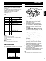
Recording Time
The amount of memory required per hour of recording is
as follows.
Bit Rate (kbps)
32
48
64
96
128
192
256
384
768 (PC1, PCM Mono)
1536 (PC2, PCM Stereo)
MB/Hour
16 MB
25 MB
33 MB
50 MB
67 MB
100 MB
136 MB
200 MB
400 MB
800 MB
PLAY / PAUSE
(6)
STOP (7)
256 kbps
1)
2)
ENGLISH
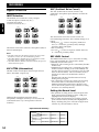
The following items can be accessed in the preset menu:
• Bitrates assigned to the SP/LP/MONO switch
• Sound detection level of the silent skip function
• Detection time of the silent skip function
• Alarm beep on or off
• Battery type used
• File format of the recorded tracks
• ID1
• ID2
• ID3
1. While power is off, press and hold the AUTO
MARK (PRESET) button and then slide the
power switch to the right.
2. The unit should enter the preset setting mode
and "Preset" should be indicated in the display.
3. The unit will then automatically display
(flashing) the first preset -- bitrate for the SP
record mode.
4. Use 1˜4 and ¢˜¡ buttons select which
preset item you would like to change. The order
of the preset menu items is the same as indicated
on a preset chart on this page.
5. Use the PLAY/PAUSE button to alternate
between changing the preset item and the
available options for the currently displayed
preset (the preset item options will flash).
6. Use 1˜4 and ¢˜¡ buttons to then select
which option you would like for the current
preset item.
7. When finished making a change to a preset item,
press the PLAY/PAUSE button to select another
preset item to change (preset item will flash).
8. When finished setting all the presets, press the
AUTO MARK (PRESET) button to save all the
changes and exit the preset menu mode.
9. If you do not want to save the changes made to
the preset menu, press the STOP button to exit
without saving the changes.
10. After exiting the preset menu mode, the unit will
return to normal operation in the stop mode.
Note
• The preset settings remain stored after the power is turned off.
9
PRESET MENU
Example: Changing the bitrate preset
5
5 5 5
5 5 5
LP
5
SP
5 5 5
5
5
5 5 5
ENGLISH
Bit rate of STEREO LP
(Long Play) REC MODE
is 128 kbps.
1 /4, ¢ / ¡
Bit rate of STEREO SP
(Short Play) REC MODE
6
5
5 5 5
5 5 5
5 5
SP
5
5 5 5
5
5
5 5 5
5 5
Bit rate is 256 kbps in
Stereo.
1 /4, ¢ / ¡
Bit rate of MONO REC
MODE.
6
5
5 5 5
5 5 5
5 5
SP
Bit rate of MONO REC
MODE is 48 kbps.
1 /4, ¢ / ¡
PCM Stereo (PC 2:
PCM 2 channels, 1536 kbps)
6
5
5
5 5 5
5
5
5 5 5
5 5 5
5 5 5
SP
5
5 5 5
5
5
5 5 5
5 5
Bit rate of MONO REC
MODE is 32 kbps.
1 /4, ¢ / ¡
Bit rate of SP REC
MODE is PCM stereo
1 /4, ¢ / ¡
5
5
5 5 5
5 5
5 5 5
5 5
Bit rate of MONO REC
MODE is PCM. (PC1:
PCM 1 channel, 768 kbps)
6
5
5
5 5 5
5 5 5
Bit rate of MONO REC
MODE is set to PCM
mono.
10
PRESET MENU
Example: Changing the file format preset
5 5 5
5 5
5 5 5
5 5 5
5 5
OVER
OVER
Display for Wave (.wav)
file format.
1 /4, ¢ / ¡
Display for internal
Alkaline battery.
1 /4, ¢ / ¡
5 5 5
5 5
5
5
5
5 5 5
5
5
5
5
5
5 5 5
ENGLISH
Example: Changing the battery type preset
5 5 5
5 5
5 5 5
OVER
OVER
Display for internal NiCad battery.
1 /4, ¢ / ¡
Display for MP2 (.mp2)
file format.
1 /4, ¢ / ¡
5 5 5
5 5
OVER
Display for internal NiMH battery.
1 /4, ¢ / ¡
Note
Ni-Cad (RB1100) is option of PMD690.
The Ni-MH battery preset ("nh") should be used in conjunction
with the optional Marantz Ni-MH battery or if commercially
available AA-sized Ni-MH batteries are used in conjunction with
the alkaline battery holder.
5
5
5 5 5
5 5
OVER
Display for Broadcast Wave (.bwf) file format.
ID Number Presets
The ID numbers are saved in the 'Extension Chunk' of the
Broadcast WAVE (BWF) file format. The IDs are defined
as follows:
ID1 :Description
ID2 :Originator
ID3 :Originator Reference
Example:
If the IDs are used in a broadcast station situation:
• ID1 could be used for the ID of the broadcasting station
• ID2 could be used for the department code
• ID3 could be used for the badge number of the reporter
ID Number Setting Operation
• The PLAY/PAUSE button will cycle through each digit
of the selected ID#.
• The 1 /4 and ¢ / ¡ buttons will increase or
decrease the digit that is flashing.
11
GENERAL FUNCTION
ENGLISH
Low Battery Warning and
Auto Power Off
Display Selections
The PMD690 has built-in power management and
emergency shut-down system when batteries are used.
Pressing the DISPLAY (TIME/DATE) button will change
the displayed information as follows.
To make sure this system operates correctly, make sure
the battery preset ("bat") in the preset menu is set
correctly. Please refer to page 9 for more information on
how to set the presets.
During Stop Mode
1st Warning
When the remaining battery time starts running low, a 1st
warning will appear. The 1st warning is when the low
battery indicator appears in the display as follows.
After the 1st warning appears, the battery has
approximately 5 to 10 minutes of total record or playback
time remaining.
Changing the Displayed Information
q Total Track #
Total Track Time
TRACK
TIME
L
-dB ∞
50
40
24
12
6
2
0
OVER
R
w Total Track #
TRACK
TOTAL
Total Remain Time
(time available for recording
at the selected bit rate)
TIME
L
-dB ∞
50
40
24
12
6
2
0
OVER
TRACK
R
2nd Warning
When the remaining battery time becomes extremely
low, the 2nd warning will appear. The 2nd warning is
when the battery indicator begins to flash as indicated in
the diagram below.
After the second warning appears, the battery has
approximately 1 to 3 minutes of recording or playback
time remaining.
5
5
TIME
L
-dB ∞
50
40
24
12
6
2
0
OVER
R
555
Note
If the alarm preset ["
"] is set ON, the PMD690 will
audibly beep to alert that the batteries life is nearing an
end.
When recording from microphone (INPUT switch position
is at MIC), beep sounds only from headphone, not from
speaker.
Shut-Down
If the unit continues to operate after the 2nd warning
appears, the unit will enter an automatic shut-down
procedure before all power is lost. Recording or playback
will stop and the unit will automatically power itself off.
12
L
-dB ∞
50
40
24
12
6
2
0
OVER
R
e Current Time
TIME
L
TRACK
555
TOTAL REMAIN TIME
-dB ∞
50
40
24
12
6
2
0
OVER
R
Note
• The time is always displayed in 24-hour time. So for example,
23:59:59 is equivalent to 11:59:59 PM.
r Current Date (MM:DD:YY)
L
-dB ∞
50
40
24
12
6
2
0
OVER
R
Note
• The date is always displayed in Month, day, Year (MM:DD:YY)
format.
GENERAL FUNCTION
During Playback and Play-Pause
During Recording and Record-Pause
q Current Track #
q Current Track #
Time elapsed on current
playing track
TRACK
Recording elapsed time on
current track
TRACK
TIME
TIME
REC
-dB ∞
50
40
24
12
6
2
0
L
OVER
-dB ∞
R
50
40
24
12
6
2
0
OVER
R
w Current Track #
Remaining time of current
playing track
TRACK
w Current Track #
Remaining recording time
(Time available for recording)
REMAIN TIME
TRACK
ENGLISH
SP
L
REMAIN TIME
REC
SP
L
-dB ∞
50
40
24
12
6
2
0
L
OVER
-dB ∞
R
50
40
24
12
6
2
0
OVER
R
e Current Track #
Accumulated time elapsed
(Total time of tracks previous
to the current track + time elapsed
on current playing track)
TRACK
TOTAL
e Current Track #
Accumulated recording time elapsed
(Total time of tracks previous to the
current track + recording time
elapsed on the current track)
TIME
TRACK
TOTAL
TIME
REC
SP
L
-dB ∞
50
40
24
12
6
2
0
OVER
R
L
-dB ∞
50
40
24
12
6
2
0
OVER
R
r Current Track #
Total playback remain time
(Total time of tracks after the
current track + remain time
of current playing track)
TRACK
TOTAL REMAIN TIME
L
-dB ∞
50
40
24
12
6
2
0
OVER
R
t Recorded Mode of
Time when the current track
the Current track
was recorded
( : Stereo,
: Mono)
Display Backlight
To Illuminate the Display:
• Press the LIGHT button:
The display backlight will turn on for 3 seconds and
then turn off.
• Press and hold the LIGHT button for more than 1
second:
The display backlight will stay on until it is turned off
by pressing the LIGHT button or if the power is turned off.
Key (Button) Lock
RECORDED
TIME
L
-dB ∞
50
40
24
12
6
2
0
OVER
R
Note
• The time is always displayed in 24-hour time. So for example,
13:21:03 is equivalent to 1:21:03 PM.
y Recorded Bit Rate
of the Current Track
Date when the current track
was recorded
The KEY LOCK switch sets the unit in the mode at the
time the switch was set. This locking function can prevent
accidental changes in a set mode or lock the unit in
recording or playback.
While the Key Lock is on, the only switches and functions
available are as follows:
• LIGHT
• POWER (except during recording)
• All the top panel slide switches except: PRE REC and
REC MODE
If a locked button is pressed, the following message will
be displayed.
RECORDED
TRACK
L
-dB ∞
R
L
50
40
24
12
6
2
0
OVER
-dB ∞
50
40
24
12
6
2
0
OVER
R
13
RECORDING
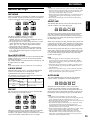
ANC (Ambient Noise Cancel)
Input Controls
The ANC (Ambient Noise Cancel) switch is only
applicable to microphone inputs but does not affect the
line input.
INPUT Selection
ENGLISH
The PMD690 can record from a variety of inputs:
• XLR micorphone connection (L/R, L)
• Internal microphone
• Line level source (L/R, L)
L
STEREO
R
L
L/R
INT
STEREO
SP
LP
L
STEREO
ANALOG OUT
LIMITER
ALC
MANUAL
REC LEVEL
MONO
OFF
ANALOG OUT
LIMITER
ALC
MANUAL
LINE
REC LEVEL
OFF
REC MODE
-15dB
-30dB
MIC
MIC ATTEN
FLAT
ON
PRE REC
KEY LOCK
ANC
The INPUT switch offers selection of microphone (MIC) or
line level (LINE) input.
Notes
• The MIC switch above the INPUT switch is only active when
the INPUT switch is set to the middle (MIC) position.
• When REC MODE is STEREO (SP or LP) and INPUT is LINE,
the input is stereo (L and R of the line inputs).
• When REC MODE is MONO and INPUT is LINE, the input is L
channel of the line inputs.
MIC ATTEN (Attenuation)
The MIC ATTEN switch adjusts the base input level for
MIC L/R and MIC L inputs only.
L
STEREO
R
ANALOG OUT
LIMITER
ALC
MANUAL
REC LEVEL
OFF
LOCK
L
L/R
INT
STEREO
SP
MIC
LINE
MONO
REC MODE
-15dB
-30dB
0dB
INPUT
OFF
LP
LOCK
KEY LOCK
0dB
INPUT
OFF
LOCK
R
MIC ATTEN
FLAT
L
L/R
INT
STEREO
SP
MIC
LINE
MONO
REC MODE
-15dB
-30dB
0dB
INPUT
OFF
LP
MIC ATTEN
FLAT
ON
PRE REC
ANC
This ANC feature allows the recorder to filter out
unwanted backgraund noise. The available settings are as
follows.
) : Cuts low frequency (150Hz and
• Band-pass (
lower, ex : wind noise, proximity effect) and high
frequency (3KHz and higher)
• Flat : No filtering
) : Cuts low frequency (150Hz and lower,
• Low-cut (
ex : wind noise, proximity effect)
REC LEVEL Control
The PMD690 offers three ways to control the recording
level: manual (MANUAL), manual with a limiter
(LIMITER), and automatic (ALC).
• MANUAL: The recording level is controlled by the REC
LEVEL knob.
• LIMITER: The recording level is controlled by the REC
LEVEL knob but a limiting circuit in the PMD690 will
not allow the input signal to overload (go past the -9dB
mark on the level meter). The recover time is short so
that the set record level is maintained as much as
possible.
The REC LED will dim when the Limiter is heavily
limiting the input signal.
• ALC (Automatic record Level Control): The recording
level in this mode is controlled exclusively by the
PMD690 and the REC LEVEL knob is disabled. The
recover time of the system is long so that the recording
level does not constantly fluctuate.
ON
Setting the Record Level
KEY LOCK
PRE REC
ANC
Adjusting the microphone attenuation allows
microphones with higher sensitivity to be recorded and
controlled the same way as microphones with lower
sensitivity.
• The optimum recording level is where the peak of the
input sound just barely flickers past the -12dB point
(highlighted in black in the display).
• The recording level should never reach the overload
point in the level meter (OVER symbol highlighted in
black). Reaching that point will result in digital noise
which is very uncomfortable for the ear.
Input Controls Summary
Switch
Input
MIC
ANC
REC LEVEL
XLR microphone Effective
connector input
Effective
Effective
Internal
Not effective
microphone Input
Effective
Effective
Not effective
Effective
Line Input
14
MIC ATTEN
Not effective
RECORDING
REC MODE
Three programmable record modes are available for each track
that is recorded. See the Preset Menu section for information
on how to change the value of each of the record modes.
L
STEREO
R
L
L/R
ANALOG OUT
LIMITER
ALC
MANUAL
STEREO
INT
MIC
SP
LP
SILENT SKIP
MONO
The SILENT SKIP button activates the silent skip mode
and the “S.SKIP” icon will be displayed.
REC MODE
-15dB
0dB
-30dB
LINE
REPEAT
INPUT
REC LEVEL
OFF
LOCK
OFF
MIC ATTEN
FLAT
ANC
The three available modes are as follows.
• MONO: Monaural recording (1 track).
Neither “SP” nor “LP” icon will be displayed when in
the record-pause or record modes.
• LP (Long Play, Stereo): This setting offers lower sound
quality than the SP mode but takes up less memory
space. The “LP” icon will be displayed during the
record-pause and record modes.
• SP (Short Play, Stereo): The setting with the highest
sound quality but the shortest record time. The “SP”
icon will be displayed during the record-pause and
record modes.
Dual LEVEL MONO
When the MIC switch is at L or at INT, and when the REC
MODE switch is set to SP or LP, DUAL LEVEL MONO
recording takes place.
The L (left) channel is recorded at normal sound level, and
R (right) channel at -15dB.
Note
DUAL LEVEL MONO works only for MIC input, not for LINE input.
L/R MIX MONO
When the MIC switch is set to L/R and the REC MODE
switch is set to MONO, the L and R inputs will be
combined and recorded onto a single track.
The chart below indiactes the relation between the MIC
switch and the REC MODE switch.
MIC Switch
L/R
REC MODE switch
SP
LP
MONO
L
INT
Dual Level Mono Recording
L/R Mix Mono
Recording
Mono Recording
The 2-second pre-record feature is active when the PRE
REC switch is set to the ON position.
STEREO
R
ANALOG OUT
LIMITER
ALC
MANUAL
REC LEVEL
OFF
LOCK
KEY LOCK
L
L/R
INT
MIC
LINE
INPUT
OFF
STEREO
SP
LP
MONO
REC MODE
-15dB
-30dB
0dB
MIC ATTEN
FLAT
ON
PRE REC
SILENT SKIP
ANC
When pre-record is active, the unit will record 2 seconds
of audio before the record button is pressed to start
recording. The benefit of the pre-record function is that it
can prevent missed or delayed starts of a recording.
AUTO MARK
PRESET
The silent skip system operates during the record mode
only and is based on the parameters set in the preset
menu. Please refer to the Preset Menu section on page 9
for information on setting the operational parameters of
the silent skip system.
When active during recording, the silent skip system will
continually look for the preset sound level, for the preset
amount of time. If the preset sound level is sensed for the
preset time, the unit will enter the record-pause mode.
The silent skip system will then stay in the record-pause
mode until a signal of approximately -30dB is input. The
unit will then re-enter the record mode and will continue
to record until the preset parameters of the silent skip
system are meet again.
Notes
• When first going into the record-pause mode from stop,
recording must be started manually with the REC/MARK
button. After recording is started, the silent skip system will
control the recording.
• If the silent skip system pauses a recording, recording can be
re-started manually by pressing the REC/MARK or PLAY/
PAUSE buttons.
• The pre-record function is always active while the silent skip
function is turned on. This is done to prevent audio from
being cut-off when the system starts and stops.
AUTO MARK
The AUTO MARK button activates the auto marking
system and the “A.MARK” icon will be displayed.
REPEAT
Stereo
recording
PRE REC
L
ERASE
FORMAT
ON
PRE REC
KEY LOCK
RENUMBER
ENGLISH
Record Settings
Notes
• For the pre-record function to operate correctly, the PMD690
must be in the record-pause mode for at least 2 seconds. If the
unit is in record-pause for less than 2 seconds, then the prerecord time will be shorter than 2 seconds.
• When recording is started with the pre-record function active,
the elapsed recording time in the display will start at the 2
seconds mark.
• Pre-record is automatically activated when the Silent Skip
feature is on.
RENUMBER
ERASE
FORMAT
SILENT SKIP
AUTO MARK
PRESET
When the auto mark feature is active, every time a
recording is paused, manually or by the Silent Skip
system, an EDL mark is placed at that point in the track.
Please refer to the section titled "The EDL" on page 21 for
information on the meaning and uses of the EDL marks.
Notes
• Auto mark can be switched on or off in any mode.
• An EDL mark is automatically placed at the beginning of each
track, regardless if the auto mark function is on or off.
• Marks are automatically placed in the normal record mode and
also in the silent skip record mode.
• The maximum number of EDL marks on a card is 255. If the
card reaches 255 marks, the auto mark function will
automatically turn off and the AUTO MARK button will not
allow the function to be re-activated.
• If the maximum number of EDL marks (255) is reached, “FULL
-P 255” will be indicated on the display for 3 seconds.
• If the maximum number of EDL marks (255) is reached,
individual EDL marks or all the EDL marks can be erased.
Please refer to the Editing EDL Marks section on page 23 for
information about erasing EDL marks.
15
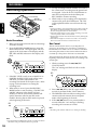
RECORDING
Recording Operation
record settings
1/4
REC CANCEL
ENGLISH
Notes
• All record settings can be changed during recording except the
REC MODE. If the REC MODE is changed during recording,
the new setting takes effect for the next track.
• If the Auto Mark feature is active during recording, every time
a track is paused an EDL mark is added.
• The REC LED will dim when the Limiter is heavily limiting the
input signal.
• The minimum length of a track is 0.5 seconds. A track of less
than 0.5 seconds will not be recorded on the card.
REC LED
REC/MARK
STOP
Basic Procedure
1. Make sure all input selection and record settings
are made correctly.
2. Press the RECORD/MARK button to enter the
Record-Pause mode. The input signal will now
appear in the level meter of the display and the
REC LED and REC indicator in the display will
flash.
55
55
REC
5
REC
TRACK
TIME
55
5
55
55 55 55
L
5
55 5 55
-dB
R
∞
50
40
24
5. To stop recording but then continue to record to
the current track, recording must be paused and
not stopped. Press the PLAY/PAUSE button to
enter the record-pause mode and then press
REC/MARK to resume recording.
6. When ready to stop recording and complete the
current track, press the STOP button. The TOC
will be updated and the unit will enter the stop
mode.
12
6
2
0
OVER
Rec Cancel
The Rec Cancel function allows a recording that is in
progress to be started over in case there is a problem or
the information recorded so far is not what was intended.
Performing this function will result in all the information
recorded up to that point in the track to be discarded.
After performing the function, the unit will re-start at the
beginning of the current track and wait for recording to be
started again.
1. While recording press the 1/4 (REC
CANCEL) button.
The "can" message will flash as follows in the
display.
REC
TRACK
TIME
REC
L
-dB
R
∞
50
40
24
12
6
2
0
OVER
Note
• Pressing the REC/MARK button during recording will add an
EDL mark at the point that the button was pressed.
16
5
SP
5 5 5
5 5
REC
REC
5 5 5
5 5
5
3. If the REC LEVEL switch is set to MANUAL or
LIMITER, the REC LEVEL knob will be active
and allow you make adjustments to the
recording level based on the input source. Refer
to page 14 for information on setting the
recording level.
4. When ready to record, press the RECORD/
MARK button to start recording. The REC LED
and REC indicator in the display will stay
steadily on and the current track number will
quickly alternate with the next EDL mark
number, showing that an EDL mark was placed
at the beginning of the track.
L
-dB ∞
50
40
24
12
6
2
0
OVER
R
2. Press 1/4 (REC CANCEL) again within 3
seconds to perform the Rec Cancel function.
3. The PMD690 will discard the recording on the
current track and re-enters the record-pause
mode at the beginning of the track.
4. If the 1/4 button is not pressed within 3
seconds while the "can" message is flashing,
recording will contonue as normal.
Note
• Recording will continue while the "can" message is flashing.
RECORDING
Source Monitor
For source monitor output and level meter, refer to the
table below.
Source monitor output according to ANALOG OUT switch (during Rec-Pause or Rec)
L
L
Stereo
Stereo
L
R
L
R
L/R
L
R
R
R
Dual Level Mono
Stereo
R
Mono
-15dB
L=R=Mono
Mono -15dB
OFF
Mono
Mono -15dB
Mono/Mono -15dB
Mono
Mono -15dB
L
L
Mono
Stereo
R
L=R=Mono
L=R=Mono
L=R=Mono
Mono
OFF
ENGLISH
Recording Mode
ANALOG OUT switch
Headphone (L channel)
Output
Headphone (R channel)
(Source
Speaker
Monitor
Line Out (L channel)
Output)
Line Out (R channel)
Digital Out
Upper
Level meter
Lower
Full Cards
The following message will appear if the PC Card is filled
during recording or if attempting to start recording with a
full card.
In order to re-use a full card, tracks need to be erased or
the card needs to be re-formatted (erases all tracks).
Maximum Number of Tracks
Each PC Card can hold a maximum of 255 tracks. When
attempting to start recording when the maximum number
of tracks is reached, the following message will be
displayed.
In order to continue to use a full card, tracks need to be
erased or the card needs to be re-formatted (erases all
tracks).
17
PLAYBACK and EDITING
Playback
ENGLISH
The standard playback mode will play all the tracks on a
card in order. Alternative playback options are the EDL
playback mode, where the EDL marks in the tracks
control playback, and the Repeat playback mode where
either a single track is continually repeated or all the
tracks on a card are continually repeated.
4. Press the DISPLAY (TIME/DATE) button to
alternate between the various track information
display options. Refer to the Display Selections
section on page 12 for more information.
5. Playback will continue until the all the
remaining tracks on the card have been played
or the STOP button is pressed to stop playback.
Reverse and Forward Search
The played back audio signal is simultaneously output to
the HEADPHONE jack, LINE OUT, DIGITAL OUT (if
turned on), and speaker (if no headphones are connected).
The HP/SPK VOLUME knob above the HEADPHONE
jack controls the output volume through the headphones
and speaker. All other outputs are a fixed level.
For output and levelmeter, refer to the table at the bottom
of this page.
ANALOG OUT
EDL PLAY
1/4 ¢/¡
During playback, press and hold the 1/4 or ¢/¡
button to perform an audible search (4 times normal
speed) in the reverse or forward direction. Release the
1/4 or ¢/¡ button to return to the normal
playback speed.
Notes
• Reverse and forward searching will continue to the next or
previous track if held down past the beginning or the end of a
track.
• If Repeat or Repeat 1 is on, the searching will follow the track
order of the Repeat mode.
• These functions are not available during EDL playback and
EDL repeat playback modes.
Fast Reverse and Forward Search
DISPLAY
PLAY / PAUSE
(6)
STOP (7)
Basic Procedure
1. From the stop mode, press the PLAY/PAUSE
button to start playback from the first track on
the card.
2. Playback can be paused at any point by pressing
the PLAY/PAUSE button. Playback is resumed
by pressing the PLAY/PAUSE button.
3. Press the DISPLAY (TIME/DATE) button to
alternate between the various track information
display options. Refer to the Display Selections
section on page for more information.
4. Playback will continue until the all the tracks on
the card have been played or the STOP button is
pressed to stop playback.
Starting Playback from a Selected Track
1. From the stop mode, press the 1/4 or ¢/
¡ button until the desired playback track is
indicated in the display.
2. Press the PLAY/PAUSE button to start playback.
3. Playback can be paused at any point by pressing
the PLAY/PAUSE button. Playback is resumed
by pressing the PLAY/PAUSE button.
18
For very large tracks, the normal reverse and forward
search speeds are too slow if certain points later in the
track need to be reached. Therefore, a 30 and 250 times
normal speed search is possible.
During playback, press the PLAY/PAUSE button to enter
the pause mode in the desired track you want to search.
Then press and hold the 1/4 or ¢/¡ button to
start fast search in the reverse or forward direction. The
search speed will be 30 times normal for 3 seconds and
then become 250 times normal for the rest of the time the
button is held. Release the 1/4 or ¢/¡ button to
return to the pause mode.
Notes
• There is no sound output in either of the fast search speeds.
• Reverse and forward searching will continue to the next or
previous track if held down past the begging or the end of a
track.
• If Repeat or Repeat 1 is on, the searching will follow the track
order of the Repeat mode.
• These functions are not available during EDL playback and
EDL repeat playback modes.
Selecting Tracks
In the stop, play, or pause modes, tracks previous or next
are selected by pressing the 1/4 and ¢/¡
buttons, corresponding the desired direction.
If the 1/4 button is pressed while playing back a
track or when paused at some point in a track, the
beginning of the current track is selected. Quick
subsequent presses of the 1/4 button will then select
previous tracks.
Note
• Erased tracks numbers are skipped when selecting tracks
unless the Renumber function is performed. Please refer to
page 20 for more information on the Renumber function.
• These functions are not available during EDL playback and
EDL repeat playback modes.
PLAYBACK and EDITING
Repeat Play, Single Track Play
Output Selection
The PMD690 can be set to repeatedly playback a single
track or all the tracks on a card. The PMD690 also can be
set to play a single track and pause.
The ANALOG OUTPUT switch is used to select the
output through the headphones, speaker, and line output.
STEREO
R
ANALOG OUT
LIMITER
ALC
MANUAL
REPEAT
LOCK
LINE
INPUT
OFF
KEY LOCK
PLAY / PAUSE
(6)
To enter the single track repeat mode, press the REPEAT
button so that the "REPEAT 1" is indicated in the display
as shown below.
REPEAT 1
TRACK
STEREO
SP
LP
MONO
REC MODE
-15dB
-30dB
0dB
MIC ATTEN
FLAT
ON
PRE REC
ANC
This switch has effect only on Stereo and Dual Mono
recordings (not Mono recordings). The normal position is
Stereo, which will playback the audio on card as it was
recorded (left channel of the recording to the left channel
of the headphone and line out and the right channel of the
recording to the right channel of the headphone and line
out).
If the L (left) or R (right) position is selected, that channel
of the recording will be output to both the left and right
channels of the headphones and line out jacks.
TIME
Auto Power Off
L
-dB ∞
INT
MIC
REC LEVEL
OFF
L
L/R
ENGLISH
L
50
40
24
12
6
2
0
OVER
R
To enter the all track repeat mode, press the REPEAT
button so that "REPEAT" is indicated in the display as
shown below.
REPEAT 1
TRACK
If the PMD690 is not operated for 5 minutes during stop
or play pause, the power is automatically shut off in oder
to conserve battery life. The alarm beep sounds for 30
seconds until the Auto Power Off.
"] is set ON, the unit will beep to
If the alarm preset ["
alart that the power is automatically shut off.
TIME
Track Editing
L
-dB ∞
50
40
24
12
6
2
0
OVER
R
To enter single track play mode, press the REPEAT button
so that the "1" is indicated in the display as shown below.
After playing the track, the PMD690 pauses at the
beginning of next track.
1
TRACK
L
-dB ∞
R
50
40
24
12
6
2
0
OVER
The PMD690 allows only two ways to directly manipulate
the recorded tracks on a card, Erase and Renumber.
Erasing a track will permanently delete a recorded track
from a card. The track number of the deleted file is
eliminated but a higher number track does not take its
place. The deleted track number remains gone until the
Renumber function is performed.
Note
• The next recorded track is always the last track on the card.
Therefore, if a deleted track is the last track on a card or a
deleted track is the last track on the card and other tracks
directly previous have been deleted, then the next recorded
track number will be a number of a track that has been deleted.
The Renumber function will re-order all the tracks on a
card in a sequential order starting from number 1. For
example, if a card has three tracks numbered 2, 4, and 6,
the Renumber function will change the track numbers to
1, 2, and 3. So the old track 2 becomes track 1, the old
track 4 becomes track 2, and the old track 6 becomes track
3.
19
PLAYBACK and EDITING
Track Erase
RENUMBER
ERASE
FORMAT
SILENT SKIP
AUTO MARK
REPEAT
PRESET
SILENT SKIP
AUTO MARK
PRESET
1. From the stop mode, press the RENUMBER
button. The "re no" message will flash in the
display as follows:
5
5 5 5
5 5
5
ENGLISH
5 5 5
5 5
5
5
ERASE
FORMAT
1. From the stop mode, use the 1/4 and ¢/
¡ buttons to select the track that is to be
deleted.
2. Press the ERASE (FORMAT) button. The "Erase"
message will flash in the display as follows.
TRACK
RENUMBER
5 5 5
5 5
REPEAT
Renumber
OVER
OVER
5 5 5
5 5
3. Press the ERASE button again to confirm the
track erase. The "Erase" message will stay
steadily on in the display as follows to indicate
that the Erase function is executing.
2. Press the RENUMBER button again to confirm
the track renumbering. The "re no" message will
stay steadily on in the display as follows to
indicate that the Renumber function is executing.
TRACK
4. When the Erase function is finished, the "done"
message is indicated in the display for 3 seconds
as follows.
3. When the Renumber function is finished, the "re
done" message is indicated in the display for 3
seconds as follows.
TRACK
4. The unit will then return to the stop mode.
5. The unit will then return to the stop mode.
Notes
• The STOP button can be used to cancel the Erase function
before it is confirmed.
• Use the Format function to erase all the tracks on a card.
20
Note
• The STOP button can be used to cancel the Renumber function
before it is confirmed.
THE EDL
The EDL marking and playback system of the PMD690
allows either a custom playback sequence to be
programmed or the audio between two specific points in
the card to be repeatedly played back.
For the custom playback sequence, the process is
completely linear, which means that the order of the
programmed sequence must correspond to the order of
the audio tracks on the card. So basically the EDL system
allows portions of the audio data stored on the card to be
skipped.
TIME
L
-dB ∞
50
40
24
6
2
0
OVER
R
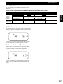
When a mark is placed, the total
quantity of mark is displayed
(total mark quantity = 192)
EDL marks are placed on the card in various ways.
MARK SELECT
ERASE
REPEAT
12
ENGLISH
EDL Marking
Every time an EDL mark is placed on a card, the total
quantity of the EDL marks on the card is displayed for
one second in the track number display area (see example
below). This is meant to provide a reference of what
number EDL mark is at that specific location and an
indication of the remaining EDL marks on the card. The
maximum number of EDL marks per card is 255.
JUMP TO MARK
EDL PLAY
TOTAL MARK
TRACK
TIME
1/4 ¢/¡
L
-dB ∞
50
40
24
12
6
2
0
OVER
R
After one second, the display
returns to the track number
display
(track number = 124)
PLAY / PAUSE
(6)
REC / MARK
STOP (7)
When the maximum number of EDL marks has been
placed, the following message will appear in the display.
During recording, marks are placed:
• At the beginning of each new track
• When the REC/MARK button is pressed
• When the AUTO MARK function is active and the
PMD690 is placed in the record-pause mode manually
or via the SILENT SKIP function
During playback or play-pause, marks are placed:
• When the REC/MARK button is pressed
Each mark has the possibility to be defined as one of four
types:
Play Mark ("P") – The basic indication for an EDL mark
and, during EDL playback, a marker to indicate that the
audio after the mark is to be played until the next EDL
mark.
Skip Mark ("S") – During EDL playback, a marker to
indicate that the audio after the mark is to be skipped
until the next EDL mark.
A Point Mark ("a") – The start point for a repeating loop.
B Point Mark ("b") – The end point for a repeating loop.
In order to place EDL marks after the above message is
displayed, either individual or all the EDL marks on the
card need to be erased. Refer to page 23 in this section for
more information on performing the EDL mark erase
functions.
Notes
• The EDL marks are stored as a separate EDL file on the card
that is only readable by the PMD690. Do not attempt to edit or
delete this file on a PC.
• If all available EDL marks have been placed, the Auto Mark
function will automatically be turned off and will not be
available again until there are available EDL marks on the
card.
• There can be only one A and one B point on each card. If an A
or B point exists on a card and a new A or B point is marked,
the new A or B point replaces the old A or B point and the old
A or B point becomes a P point.
All new EDL marks are initially placed as Play marks.
After recording or playback is complete, the definition of
all the EDL marks on the card can be changed. Refer to
page 23 in this section for more information on how to
change a mark type.
21
THE EDL
Auto Mark
The Auto Mark function automatically places an EDL
mark on the card when the PMD690 enters the recordpause mode from the record mode. The record-pause
mode is entered either manually via the PLAY/PAUSE
button or in an automated way via the Silent Skip system.
Display of Located EDL Marks
When an EDL mark is located, the number of that
particular EDL mark is displayed for one second in the
track mark display area. Then the track number where
the mark is located is displayed as the example below
indicates.
ENGLISH
The Auto Mark function can be turned on and off at any
time. When Auto Mark is on, the "A.MARK" icon in the
display will light as follows.
TIME
L
-dB ∞
A.MARK
50
40
24
TRACK
6
2
0
OVER
TIME
REC
When a mark is located, the mark
number accessed is displayed
(mark number = 132)
L
-dB ∞
12
R
50
40
24
12
6
2
0
OVER
R
TRACK
TIME
Please refer to the Record Settings section on page 15 for
more information on the Auto Mark function.
L
-dB ∞
50
40
24
12
6
2
0
OVER
R
Searching for EDL Marks
After one second, the track
number of where the mark was
placed is displayed
(track number = 121)
The EDL marks on the card can be searched for in either
the forward or reverse direction during STOP, PLAY, and
PLAY PAUSE.
Forward EDL Mark Search
EDL marks can be searched for in the forward direction
by holding down the JUMP TO MARK button and
pressing the ¢/¡ button. Every time the ¢/¡
button is pressed, the PMD690 will search for the next
mark on the card. If forward search is performed while at
the last EDL mark on the card, the PMD690 will start
searching from the beginning of the card (EDL mark 1).
Reverse EDL Mark Search
EDL marks can searched for in the reverse direction by
holding down the JUMP TO MARK button and pressing
the 1/4 button. Every time the 1/4 button is
pressed, the PMD690 will search for the previous mark on
the card. If previous search is performed while at the first
EDL mark on the card, the PMD690 will start searching
from the end of the card (last EDL mark).
22
Displaying the Total Number Of EDL Marks
While in the stop mode, the total number of EDL marks
on the card can be displayed by holding down the TOTAL
MARK button and then pressing the REC/MARK button.
The total number of EDL marks on the card will then be
displayed for 3 seconds as indicated below.
THE EDL
After all the EDL marks are placed in the audio tracks of a
card, they can be edited by changing the mark types,
erasing specific marks, or erasing all the marks.
Changing a Mark Type
Locate the EDL mark to be changed by using the mark
search functions. When the desired EDL mark is located,
press the MARK SELECT button to display the current
mark type. Each subsequent press of the MARK SELECT
button will then change the mark type in the following
order.
Erasing an EDL Mark
REPEAT
RENUMBER
ERASE
SILENT SKIP
FORMAT
AUTO MARK
PRESET
Locate the EDL mark to be erased by using the mark
search functions. When the desired EDL mark is located,
press the ERASE button so that the display flashes the
mark type of the selected mark followed by the "Erase"
message. Press the ERASE button again to confirm the
Erase function (or press the STOP button to cancel). When
the erase operation is complete, the "done" message will
be displayed and then the unit will return to the point
where the mark was in the pause mode.
ENGLISH
Editing EDL Marks
Notes
• The mark type can also be automatically saved by searching
for the next or previous mark on the card.
• There can be only one A and one B point on each card. If an A
or B point exists on a card and a new A or B point is marked,
the new A or B point replaces the old A or B point and the old
A or B point becomes a P point.
The complete procedure is displayed as follows.
24
12
6
2
0
OVER
5
40
5 5 5 5 5
5 5
50
5
-dB ∞
5 5 5 5 5
5 5
OVER
P : Play
Waiting for confirmation.
Press the ERASE button to confirm.
Press the STOP button to cancel.
-dB ∞
50
40
24
12
6
2
0
OVER
S : Skip
Erase operation executing.
-dB ∞
50
40
24
12
6
2
0
OVER
-a : Repeat Point A
Erase complete.
TRACK
-dB ∞
50
40
24
12
6
2
0
OVER
-dB ∞
50
40
24
12
6
2
0
OVER
-b : Repeat Point B
The PMD690 returns to the location of the erased mark.
When the desired mark type is displayed, press the
PLAY/PAUSE button to save the mark type. If you
decide not to change the mark, press the STOP button to
cancel the mark changing operation.
Note
• Erasing an EDL mark will automatically renumber all the EDL
marks on the card. The result is similar to the track renumber
function that is described on page 19 in the Track Editing section.
23
THE EDL
Erasing all the EDL Marks
EDL Playback
ERASE
JUMP TO MARK
The EDL playback mode will start playing back from the
current position but will observe the direction of the
programmed EDL marks.
EDL PLAY
ENGLISH
From the STOP mode, hold the JUMP TO MARK button
and press the ERASE button so that the display flashes the
"EdL Erase" message. Continue to hold the JUMP TO
MARK button and press the ERASE button again to
confirm the EDL Erase function (or press the STOP button
to cancel). When the erase operation is complete, the
"done" message will be displayed.
5 5 5 5 5 5 5
5 5
To start EDL playback, hold the EDL PLAY button and
press the PLAY/PAUSE button. EDL playback will then
start playing the audio on the card starting from the first
track (unless it is skipped). An example of a programmed
EDL playback is as follows.
Current Position
JUMP
JUMP
5
5
The complete procedure is displayed as follows.
PLAY / PAUSE
(6)
Recorded Contents
5 5 5 5 5 5 5
5 5
OVER
Waiting for confirmation.
Press the ERASE button
while holding down the JUMP
TO MARK button to confirm.
Press the STOP button to
cancel.
SKIP
PLAY
SKIP
SKIP
PLAY
Play Back Part of Recorded Contents
Skipped Part of Recorded Contents
EDL playback can be paused at any time by pressing the
PLAY/PAUSE button. Playback is resumed by again
pressing the PLAY/PAUSE button.
To exit from EDL playback, hold the EDL playback and
press the PLAY/PAUSE button during EDL playback or
EDL play pause. The PMD690 will returns to the normal
playback mode, and starts playback from current position.
EDL Erase operation
executing.
EDL playback can be stopped at any time by pressing the
STOP button. The PMD690 will return to the normal stop
mode after EDL playback is stopped.
Notes
• If a Skip ("S") mark is the last mark on a card, then the audio
after the mark until the end of the card is skipped.
• Searching and track selection via the 1˜4 and ¢˜¡
buttons is not available during EDL playback.
• If EDL playback is started but there are no EDL marks on the
card, the following message will be displayed:
EDL Erase complete.
24
THE EDL
ERASE
SILENT SKIP
FORMAT
5 5
AUTO MARK
REPEAT
TRACK
TIME
PRESET
L
-dB ∞
To start EDL repeat playback, hold the EDL PLAY button
and press the PLAY/PAUSE button. Once playback
starts, press the RPT/SGL button. EDL repeat playback
will then start playing the audio on the card starting from
the A ("a") mark and continuing until the B ("b") mark.
An example of EDL repeat playback is as follows.
JUMP
40
24
12
6
2
0
OVER
If EDL playback or EDL repeat playback is paused, both
the Play (3) and Pause (8) icons will flash in the display
as follows:
5
5 5 5
JUMP
5
TRACK
5 5 5
JUMP
50
R
ENGLISH
RENUMBER
During EDL playback and EDL repeat playback, the Play
icon (3) in the display will flash as follows:
5
REPEAT
EDL Playback and EDL Repeat
Playback Display
5
EDL repeat playback works the same way as normal EDL
playback except that playback will start at the
programmed A ("a") mark and continue until the
programmed B ("b") mark; and then return to A mark to
repeat the loop.
55
EDL Repeat Playback
Recorded Contents
TIME
L
Repeat-a
SKIP
PLAY
SKIP
SKIP
PLAY
Repeat-b
-dB ∞
50
40
24
12
6
2
0
OVER
R
Play Back Part of Recorded Contents
Skipped Part of Recorded Contents
EDL repeat playback can be paused at any time by
pressing the PLAY/PAUSE button. Playback is resumed
by again pressing the PLAY/PAUSE button.
EDL repeat playback can be stopped at any time by
pressing the STOP button. The PMD690 will return to the
normal stop mode after EDL repeat playback is stopped.
Notes
• If a Skip ("S") mark is the last mark in the loop, then the audio
after the mark until the end of the loop is skipped.
• There can be only one A and one B point on each card. If an A
or B point exists on a card and a new A or B point is marked,
the new A or B point replaces the old A or B point and the old
A or B point becomes a P point.
• Searching and track selection via the 1˜4 and ¢˜¡
buttons is not available during EDL repeat playback.
• If EDL repeat playback is started but there is only one A or B
mark on the card, the following message will be displayed:
25
ADDITIONAL INFORMATION
File Structure
The error message below will be displayed if the card is
ejected during playback, recording, or editing. It will also
be displayed upon power-up if power was suddenly lost
during the previous recording, playback, or editing
operation.
File Format
The PMD690 records files onto PC Cards in an MS-DOSTM
and Windows TM compatible file format. Each track
recorded on the card is stored in its own folder, which
carries the same name as the track file. Below is an
example of the file structure on a card.
ENGLISH
Error Messages
FOLDER
\
(Error Card)
After the card error message is displayed, the PMD690
will display the following message to indicate that the
PMD690 is attempting to recover the data on the card.
nnn:
xxx:
(CHEcking Card)
If the recovery is successful, the following message will be
displayed and then the unit will enter the stop mode.
(CHEck done)
If the recovery is unsuccessful, the following message will
be displayed to indicate that the data on the card is unrecoverable and that the card needs to be formatted to be
used again.
(broken Card)
26
TRACK FILE
PMD690
TRACK
NUMBER
MZ000001
MZ000002
MZ000003
\
\
\
MZ000001.xxx
MZ000002.xxx
MZ000003.xxx
1
2
3
MZ000nnn
\
MZ000nnn.xxx
nnn
Last track number
BWF (Brodcast Wave format* )
WAV (Wave format*)
MP2 (MPEG1 layer 2 format*)
* File format is selected in the preset menu before
recording. Refer to page 9 for more information on the
different formats.
Notes
• Files on a card recorded by the PMD690 that are modified by a
PC will no longer be able to be read by the PMD690.
• Each PC Card formatted in the PMD690 will contain, in
addition to the audio tracks, an EDL and TOC (mztoc.inf) file
that can only be read by the PMD690. Do not attempt to edit or
delete these files on a PC.
ADDITIONAL INFORMATION
If your unit fails to operate normally, check the symptoms
and solutions described below. If the problem persists
and cannot be corrected, please contact the Marantz
Professional dealer from whom the product was
purchased.
The unit does not respond to operations.
• Make sure that fresh batteries are installed, or that the
AC power adaptor is connected properly.
• Make sure the PC Card is fully inserted.
• Turn power OFF, then ON.
The unit does not work normally.
• Check all settings.
Playback is not possible.
• Check to make sure the PMD690 acknowledges track
information on the PC Card.
Audio is not output through the headphones or
speaker.
• Check the HP/SPK VOLUME level.
• Check a different track or card to see if the problem is
consistent with other tracks or cards.
Audio is not output through the Digital Out.
• Check that the DIGITAL OUT ON/OFF switch is set to
the ON position.
• Note that the Digital output is automatically disabled
during recording.
Recording is not possible.
• Check that less than 255 tracks are recorded on the card
(255 tracks are the maximum number of recorded
tracks).
• Check to make sure that the PMD690 acknowledges the
PC Card.
No signal is recorded from a microphone input.
• Check that the INPUT switch is set to the middle
position (MIC) and that the MIC switch is set to the
correct microphone selection.
• Check that the REC LEVEL switch is set to the correct
position. In MANUAL and LIMITER modes, the REC
LEVEL knob controls the recording level. During ALC,
the recording level is controlled automatically by the
PMD690.
• Check if the microphones you are using require
phantom power (condensor microphones). If they do,
make sure the phantom power switch on the right side
of the PMD690 is in the ON position.
File playback on a PC results in poor sound.
• Different PC sound cards and playback programs will
result in different sound quality.
• The PMD690 records all the audio files with a sampling
frequency of 48kHz. Some PC programs convert the
files into 44.1kHz (using a sample rate converter) in
order to play or edit the files, which may cause a
degradation in the sound quality. Only high quality
sample rate converters should be used.
ENGLISH
Troubleshooting
Excessive noise.
• Check all connected cables for proper connection.
Files recorded on the PMD690 are not able to be
read by a PC.
• Some PCs may not be able to understand MP2 files
recorded with the Wave (.wav) file extension. If you
happen to have files in this situation, rename the files
using a PC so that the file extension is changed to MP2
(.mp2).
• Some playback and editing programs do not support the
MP2 or Broadcast Wave (.bwf) formats. If you are
having trouble playing or editing MP2 or Broadcast
Wave files, consult the Marantz Professional website at
www.marantz.com for links to programs that support
MP2 and Broadcast Wave.
The rechargeable battery is not charging.
• Check that the CHARGE switch is set to the ON
position.
• Make sure the CHARGE LED is flashing during
charging and then stays steadily on when charging is
complete.
• Make sure the AC Adaptor is correctly plugged in and
the power on the unit is turned off.
Rechargeable battery life is very low.
• Make sure to fully charge and discharge the battery
with each use. NiCad batteries have a memory effect,
which means that the life of the battery will become
much lower if the battery is only partially discharged
(used) and then re-charged.
• If the battery has been heavily used or is old, it may
need to be replaced with a new one. Contact your
dealer directly to purchase a new battery.
Care and Maintenance
To clean the cabinet
Use a soft cloth slightly moistened with mild detergent
solution.
27
ADDITIONAL INFORMATION
Inputs
Specifications
Digital audio system
ENGLISH
System
Digital audio recorder
Usable Media
Approved PCMCIA PC Cards and HDD cards
Recording and reading method
MPEG1 Layer II compression
16 bit linear PCM
Recording Bit rate (Selectable by preset)
MONO
768 kbps (PCM), 192, 128, 96, 64, 48, 32 kbps (MPEG)
LP (Long Play mode, Stereo)
192, 128, 96, 64 kbps (MPEG, Joint Stereo)
SP (Standard Play mode, Stereo)
1536 kbps (PCM), 384, 256 kbps (MPEG, Joint Stereo)
The amount of memory required per hour of recording:
Bit Rate (kbps)
MB/Hour
32
16 MB
48
25 MB
64
33 MB
96
50 MB
128
67 MB
192
100 MB
256
136 MB
384
200 MB
768 (PC1, PCM Mono)
400 MB
1536 (PC2, PCM Stereo)
800 MB
Sampling frequency
48 kHz
Number of channels
2/1 (stereo/mono)
Frequency Response
22,000 Hz ±0.5 dB (at digital)
Signal-to-Noise Ratio (IEC-A weighted)
80 dB
Total Harmonic Distortion (at 0 VU)
0.03 %
Dynamic Range
85dB
28
MIC/LINE IN L/R
Type: XLR (1:GND, 2:HOT, 3:COLD)
Input Sensitivity (MIC): -68 dBu/9 kilohms
Input Sensitivity (LINE): -20 dBu/47 kilohms
Outputs
LINE OUT L/R
Type: RCA jack
Standard level: 2 Vrms max./2 kilohms
DIGITAL OUT
Type: RCA jack
Output impedance: 75 ohms
Standard output level: 0.5 Vp-p
Sampling frequency: 48 kHz
Format: SPDIF (IEC-958 Type II)
GENERAL
Headphone Output power
15 mW/32 ohms
Speaker Output Power
200 mW
Phantom Power
+48V, 5mA
Power Requirement
13 V, 1.0 A
Power Consumption
Recording: 5.2 W
Charging: 12 W
Power off: 10 mW
Dimensions (W x H x D)
264 x 52 x 185 mm
(10.4" x 2.0" x 7.3")
Weight
1.3 kg (2 lbs. 14 oz.)
Included Accessories
AC adaptor: 1
Battery holder: 1
Carrying Strap: 1
User Guide: 1
Optional Accessories
Ni-Cad Battery pack (RB1100PMD)
Carrying Case (CLC690PMD)
Specifications subject to change without notice.
SETTING UP
Index of Parts, Controls, and Display
Top Panel
ENGLISH
PORTABLE PC CARD RECORDER PMD690
@4
FRANÇAIS
L
STEREO
R
L
L/R
STEREO
INT
SP
LP
MONO
q, w, e
ANALOG OUT
LIMITER
ALC
MANUAL
PORTUGUÊS
r, t, y
REC LEVEL
OFF
u, i, o
LOCK
MIC
LINE
INPUT
OFF
REC MODE
-15dB
-30dB
JUMP TO MARK
EDL PLAY
MARK SELECT
TOTAL MARK
MIC ATTEN
FLAT
REC/MARK
RENUMBER
REC
CANCEL
ON
PRE REC
KEY LOCK
REPEAT
@3
MIC
0dB
ERASE
PLAY/PAUSE
STOP
ANC
SILENT SKIP
AUTO MARK
FORMAT
PRESET
POWER
ESPAÑOL
!0 !1 !2 !3 !4
@2
Front Panel
e
w
DISPLAY
HP/SPK VOLUME
!5
r t
LIGHT
TIME/DATE
y
u
REC
L
R
HEADPHONE
q
EJECT
o
1
!9 !6 @0 !8 @1
!7
i
REC
LEVEL
SETTING UP
Top Panel
Front Panel
q
w
e
r
t
y
u
i
o
!0
!1
!2
!3
!4
!5
!6
ANALOG OUT switch (page 17, 18)
q
w
e
r
t
y
u
i
o
!7
!8
!9
@0
@1
@2
@3
@4
1 /4 REC CANCEL button (page 16, 18, 20)
REC LEVEL switch (page 14)
INPUT switch (page 14)
MIC ATTENUATION switch (page 14)
KEY LOCK switch (page 13)
PRE REC switch (page 15)
Ambient Noise Cancel switch (page 14)
REPEAT button (page 19)
RENUMBER button (page 20)
DISPLAY, TIME/DATE key (page 4, 12)
LIGHT key (page 13)
REC LED (page 14, 16)
Display (page 12, 13)
REC LEVEL knob (page 14)
ENGLISH
REC MODE switch (page 15)
HP/SPK VOLUME knob (page 18)
EJECT button (page 5)
PC Card slot (page 5)
FRANÇAIS
MIC switch (page 14)
HEADPHONE jack (page 8)
AUTO MARK, PRESET button (page 9, 15)
MARK SELECT button (page 23)
JUMP TO MARK, EDL PLAY, TOTAL MARK
button (page 22, 24)
¢ /¡ button (page 18, 20)
ESPAÑOL
SILENT SKIP button (page 15)
PORTUGUÊS
ERASE, FORMAT button (page 6, 20)
REC/MARK button (page 16, 21)
PLAY/PAUSE button (page 16, 18, 19)
STOP button (page 16, 18)
POWER key (page 4)
INT microphone (page 14)
SPEAKER (page 18)
2
SETTING UP
Left Panel
DC IN 13V
ENGLISH
q
FRANÇAIS
PORTUGUÊS
q
w
e
r
t
y
DIGITAL OUT
(SPDIF–48kHz)
CHARGE
ON
OFF
w
e
REMOTE
OFF
r
ON
t
y
DC IN 13V (page 3)
CHARGE LED (page 3)
CHARGE switch (page 3)
REMOTE IN jack (page 8)
DIGITAL OUT switch (page 8)
DIGITAL OUT jack (page 8)
ESPAÑOL
Right Panel
L
MIC/LINE IN
R
PHANTOM
+48V
L
LINE OUT
R
ON
OFF
q GND
q
q LINE OUT jacks (page 7)
w MIC/LINE IN jacks (page 7)
e PHANTOM +48V switch (page 7)
3
w
HOT
w
e COLD
e
SETTING UP
Display
o r w !6
S.SKIP
q
y
!7 u
!4
REPEAT 1
TRACK
et
A.MARK
!5
RECORDED
TOTAL REMAIN TIME
ENGLISH
REC
SP LP
L
50
40
24
12
6
2
0
OVER
!1
!2
!0
FRANÇAIS
R
!3
No
q
Item
TRACK
Type
Explanation.
Turns on while track number is displayed.
w
Track Number
7 Seg x 3 digits
Displays track number, mark number, mark quantity (001~255),
error messages, mode messages.
e
r
TOTAL
1REC1
Turns on while Total Time is displayed.
Blinks while in Record-Pause, Steadily on while Recording.
t
y
REMAIN
REPEAT
Turns on while Remain Time is displayed.
Turns on while in the REPEAT, REPEAT 1, and EDL repeat playback modes.
u
i
Time
PLAY
o
PAUSE
on while playing back and recording.
Turns on while in play-pause and record-pause modes.
!0
!1
LP
SP
Turns on while in the Long Play mode recording mode.
Turns on while in the Short Play mode recording mode.
!2
!3
Battery Indicator
Level Meter
Turns on when Battery is half consumed, blinks when battery is near end.
0dB=2V output.
!4
!5
A.MARK
1RECORDED1
Turns on while the Auto Mark function is active.
Turns on while recorded time or date is displayed.
!6
!7
S.SKIP
z
Turns on while the Silent Skip recording mode is active.
Turns on while in the REPEAT 1 playback mode or Single Track Play mode.
L
STEREO
R
ANALOG OUT
LIMITER
ALC
MANUAL
REC LEVEL
OFF
LOCK
7Seg x 6 digits
L
L/R
STEREO
INT
MIC
LINE
INPUT
OFF
14dots
SP
LP
Diplays time, date and messages.
Blinks during the EDL playback, and record-pause modes. Steadily
MONO
REC MODE
-15dB
-30dB
MIC
0dB
MIC ATTEN
FLAT
MARK SELECT
JUMP TO MARK
EDL PLAY
TOTAL MARK
REC/MARK
REPEAT
RENUMBER
REC
CANCEL
ON
PRE REC
KEY LOCK
PORTUGUÊS
-dB ∞
ESPAÑOL
i
ERASE
FORMAT
PLAY/PAUSE
STOP
ANC
SILENT SKIP
AUTO MARK
PRESET
4
is a registered trademark.
Printed in Japan
01 / 03 MITs 470S851250