Transcript
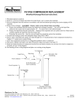
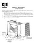
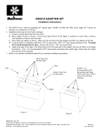
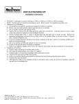
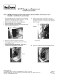
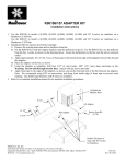
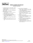
K00152 KEY CARD KIT
Installation Instructions
Parts List
Item Quantity
Part Number
Description
1.
2.
3.
4.
5.
6.
7.
8.
9.
10.
11.
12.
13.
14.
2032623
2502183
5202063
5428781
5429061
5544541
5544591
6028781
6028861
6269914
6270314
8011233
8132303
8136153
Wiring Harness
Bushing - Heyco
Sheet Metal Screw
#6 Hex Nut
#8 Hex Nut
#6 Lock Washer
#8 Lock Washer
Switch Cover
Key Card Weldment
Key Card Access Plate Studweld
Access Switch
Instruction Sheet
Label - Insert Room Key Card
Label - Wiring Diagram
1
1
1
2
4
2
4
1
1
1
1
1
1
1
Instructions
1. Disconnect power.
2. Cut out and tape hole pattern to outside of dispenser door.
3. Use a sharp punch to mark all six holes.
4. Remove pattern from dispenser door.
5. Drill six 1/4” diameter holes through the door liner using punch marks.
6. Cut out material between the two middle holes, as shown on pattern.
7. Insert the studs on the key card access plate into the four mounting holes from the front side.
8. Assemble the access switch assembly to the studs with the lock washers and #8-32 hex nuts (see diagram 1).
9. Disconnect the switch wire harness and plug the male end of the key card assembly wire harness in its place.
10. Plug the switch wire harness into the female end of the key card assembly wire harness.
11. Attach the wiring diagram sticker to wiring diagram on the control box cover (see diagram 2).
12. Attach switch cover to the key card assembly with sheet metal screw (see diagram 1).
13. Connect power and test. Insert room key card into slot and push ice button switch.
Manitowoc Ice, Inc.
2110 South 26 Street, P.O. Box 1720, Manitowoc, WI 54221-1720 USA
Telephone 920-682-0161, Fax - Sales: 920-683-7589, Service/Parts: 920-683-7585, Other: 920-683-7879
Web Site - www.manitowocice.com
8011233
Sheet 1 of 3
Rev. 05/31/01