1
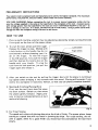
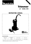
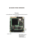
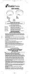
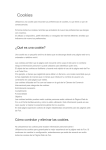
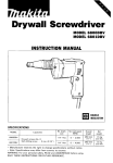
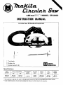
l S S m m ( 7 X ' ' ) MODEL S R l S O O
INSTRUCTION MANUAL
1
Circular Saw & Standard Equipment
Ii
1
j
I
,I
!
i
j
i
~
I
I
I
I
i
1'
-2'
Tool body
Guide rule
DOUBLE
INSULATION
P Socket wrench (9)
Specifications
Blade
diameter
Max. cutting depth
45O
1
goo
Continuous
rating
( I nput)
No load
speed
Overall
length
Net
weight
Power
supply
cord
I
185"
45"
65"
290"
4.2kg
2.5 m
BEFORE CONNECTING YOUR TOOL
TO A POWER SOURCE
Be sure you have read all
GENERAL POWER TOOL SAFETY RULES
GENERAL SAFETY PRECAUTIONS
1. KEEP WORK AREA CLEAN. Cluttered areas and benches invite accidents.
2. AVOID DANGEROUS ENVIRONMENT. Don't use power tools in damp or wet
locations. Keep work area well lit. Do not expose power tool in rain.
3. KEEP CHILDREN AWAY. All visitors should be kept safe distance from work area.
4. STORE IDLE TOOLS. When not in use, tools should be stored in dry, high or
locked-up place-out of the reach of children.
5. DON'T FORCE TOOL.
* it was designed.
It will do the job better and safer a t the rate for which
6. USE RIGHT TOOL. Don't force small tool or attachment to do the job of a heavyduty tool.
7. WEAR PROPER APPAREL. No loose clothing or jewelry to get caught in moving
parts. Rubber gloves and footwear are recommended when working outdoors.
8. USE SAFETY GLASSES. Use safety glasses with most tools. Also face or dust
mask if cutting operation is dusty.
9. DON'T ABUSE CORD. Never carry tool by cord or yank it to disconnect from
receptacle. Keep cord from heat, oil, and sharp edges.
10. SECURE WORK. Use clamps or vise to hold work. It's safer than using your hand
and it frees both hands to operate tool.
11. DON'T OVERREACH. Keep proper footing and balance a t all times.
12. MAINTAIN TOOLS WITH CARE. Keep tools sharp and clean for best and safest
performance. Follow instructions for lubricating and changing accessories.
13. DISCONNECT TOOLS. When not in use; before servicing; when changing bladeor adjusting guides.
14. REMOVE ADJUSTING KEYS AND WRENCHES. Form habit of checking to see
that keys and adjusting wrenches are removed from tool before turning it on.
15. AVOID ACCIDENTAL STARTING. Don't carry plugged-in tool with finger on
switch. Be sure switch is OFF when plugging in.
16. OUTDOOR USE EXTENSION CORDS. When tool is used outdoors, use only extension cords suitable for use outdoors and so marked.
17. Keep Guards i n Place and in Working Order.
18. Keep Blades Sharp.
19. Keep Hands Away from Cutting Area.
20. REPLACEMENT PARTS. When servicing use only identical replacement parts.
PRELIMINARY INSTRUCTIONS
Your electric tool is precision built and manufactured t o satisfy the highest standards. For maximum
performance, long tool life, and your safety, follow these instructions carefully.
VOLTAGE WARNING: Before connecting the tool to a power source (receptacle, outlet, etc.) be
sure the voltage supplied is the same as that specified on the nameplate of the tool. A power source
with voltage greater than that specified for the tool can result i n SERIOUS INJURY t o the user as
well as damage to the tool. I f in doubt, DO NOT PLUG I N THE TOOL. Using a power source with
voltage less than the nameplate rating is harmful t o the motor.
-
HOW TO USE
1i .
Planiqg depth (cutting volume) may be adjusted as desired by simply turning the knob
(front grip) on the front of the power planer.
2. To start the tool, simply pull the trigger.
Release the trigqer
_ _ to stop. Models with
a lock button G S the handle may be run
continuously without keeping your finger on the trigger. To lock the trlgqer
in the ON position, first pull the trigger
and then depress the lock button on the
handle with your thumb. To stop the
tool from the lock position, just pull the
?rigger again and release it.
Lock button
Trigger switch
I
r
3. After you switch on the tool by pulling the trigger, h a i t until the planer is running a t
top speed before bringing it into contact with the wood. Planing will be easier if you
incline the workpiece in stationary fashion, so that you can plane somewhat downhill.
4. Starting & Finishing Planing Work
First, rest the tool front shoe flat upon
the work surface. Switch on, then move
the planer gently forward. Apply pressure to tool as indicated (photo), a t start
and end of planing.
Fig. 2
5. For Fine Finishes
The speed and volume of planing determine the kind of finish. The power planer keeps
cutting a t a speed that will not result in jamming by chips. For rough cutting, the volume is upped, while for a good finish you should cut less and advance the tool more
slowly.
3
REPLACING INSTALLING PLANER BLADES
After unplugging the tool, you may remove
the planer blades on the tool drum by unscrewing the three installation bolts with
the socket wrench provided. The clamp
plate comes off together with the blades.
See Photo.
4-c
Fig. 3
When you install new or sharpened blades,
H e x . flange hd. bo
first clean out a l l chips or foreign matter
adhering to the drum or blades. Use blades
of the same dimensions and weight, or
Drum
drum oscillation/vibralion will result, causPlaner
blade
ing poor planing action and, eventually,
Blade c l a m p pla
tool breakdown.
Fig. 4
Screw the blade onto the adjust plate, slip
it intd the groove on the drum, then fit the blade clamp on over it. Fasten with hex flange
hd. bolt. See diagram a t above.
When properly installed, the side of the blade should be flush with the outside edge of the
front and back shoes.
For rabbeting, the edge of the blade
should be made t o protrude outside slightly (0.3 mm - 0.6 mm : 1/64” - 1/32”).
Otherwise, nicks and generally poor rabbeting results.
Fig. 5
Using blade gauge for even blade setting
Although the blade protrusion for desired cutting depth IS easily obtainea by turning the
front knob, the setting of the blade itself in relation to the work may require adjustment
This is done conveniently with the blade gauge provided.
First, remove the blade from the tool by unscrewing the hex bolts. Now set the blade on
the gauge base so that the cutting edge of the blade is perfectly flush with the inside surface of the gauge plate. Loosen the screws on the adjust plate (if they are not already so),
then simply press in the heel of the adjust plate flush with the back side of the gauge base
and tighten the two Phillips screws on top. This insures that your blade tip will be set
properly when remounted in the tool so as to provide perfectly even planing.
( 1 ) Set blade tip flush with inside surface of gauge
plate
(2) Press in heel of adjust p l a t e flush with back
sidp of gauge base
(3)Tighten two Phillips screws to hold blade in
place
Fig. 6
4
FOR THE CORRECT PLANER BLADE SETTING
Your planing surface will end up unsmooth and not level, unless the blade is set properly
and securely. The blade must be mounted so that the cutting edge is absolutely level, that
is, parallel t o the surface of the rear base. Below are some examples of proper and improper settings.
( A ) Front base (Movable shoe)
Although this side view cannot show
it, the edges of the blades run perfectly parallel to the rear base surface.
Cause One or both blades fails to
have edge parallel to rear base
line.
Nicks i n
surface
Cause. One or both blade edges fails
t o protrude enough in relation
t o rear base line.
Cause One or both blade edges protrudes too far i n relation to
rear base line
Gouging
SHARPENING PLANER BLADES
Although a power planer considerably outperforms an ordinary hand plane, by the
same token the blades become dull faster.
Always keep your blades sharp for the best
performance possible. Use the sharpening
holder (photo) t o remove nicks and produce a fine edge.
I
Sharpening holder
I
Fig. 7
First, loosen the 2 wing nuts on the holder
and insert blades A and B as in figure a t
ight, so that they contact side C and D.
Then tighten wing nuts.
Immerse dressing stone in water for 2 or 3
minutes before sharpening. Grip the holder so that blades both contact the dressing
stone for simultaneous sharpening a t the
same angle. Stock removal is possible up to
7.5 mm (5/16”).Blades may be used down
t o 24.5mm ( I ” ) .
Fig. 9
5
USE OF NOZZLE ASSEMBLY
Use of the special nozzle assembly (accessory attachment) will prevent chip scatter,
making for a clean work area.
\
Nozzle assembly
Fig. 1(
ATTACHING NOZZLE ASSEMBLY
The nozzle assembly may be attached after
the chip cover on the tool body i s removed.
When slipping on the assembly, f i t the pin
on it into the rear cover hole. Use the chip
cover screws to fasten it in piace.
Fig. 11
MAINTENANCE
Caibon brushes
Replace carbon brushes when they wear
down to about 5 mm (YIS") or sparking
will occur.
Both brushes should be changed a t the
same time.
ACCESSORIES
CAUTION: The use of any other accessories not specified in this manual might
be hazardous.
0
Replacement blades
Width! 8 2 mm !3-1/4")
Part No. 731001-4
0
Planer blades
(Material:
_ .
- Tunasten-carbide)
Width. 8 2 mm-(3-1/4")
0
Blade gauge assembly
Part No. 123062-2
0
Sharpening holder assembly
Part No. 123004-6
0
Planer stand
Part No. 122125-1
'i
0
Nozzle assembly
Part No. 122194-2
0
0
Guide rule
Part No. 164371-0
Dressing stone
Part No. 741802-2
Socket wrench
0
Part No. 782209-3
Screwdriver
Part No. 783002-8
---.
!
:
em-F #e*.,-
8
0
--.
Hex flange hd. bolt
Part No. 2 5 1 6 0 9 - 3
4 4
6
185mm(7Y4")ClRCULAR S A W
Model SR 1800
MODEL S R l 8 W
1
7
':iM
,":,
DESCRIPTION
Ab:
'L,'df
DESCRIPTION
MACHZE
01
1
Switch
1
Single Pole IWithout Lock Button1
SGE115CDY lFor U S A 1
Single Pole IWifh Squared Waher E Without L w k
Buttonl GPAH 4 IFor Canadd
42
1
43
1
C S N Bolt M 6 x x )
F Washer 6
1
44
Lever Plate
45
1
Lock Plate
4b
2
C S N Bolt M6x20
47
I
Plate
48
1
P H Screw M4r6 IWith Washer]
1
F Washer 6
49
1
50
1
ti Nux M 6
51
t
C h Screw M5x20
52
1
i(.ibber S'eevr
5
'
7
6
%rev. hlSXB
4aSE x S ; f M B - Y
IA?>emblebItems
5? & 54,
Bore
4CCESSOH IES
4 M
1
40;
1
402
1
'
Chiset Tooth Combinrtion Saw Blrde 1 8 5
,
Socket Wrench 9
I
I
Guide Pclr
7hCLJrCib!€&utmc W 4 " b . u .
Anjo. Aichi, h p 8 n
PRINTED IN JAPAN
1981-1-N
I