1
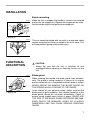
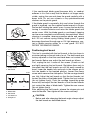
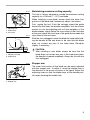
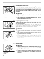
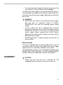
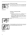
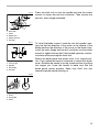
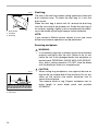
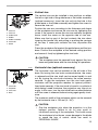
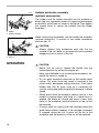
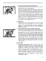
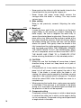
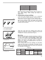
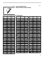
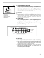
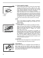
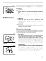
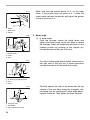
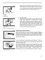
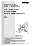
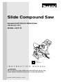
Slide Compound Saw
Equipped with Electric Blade Brake
190 mm (7-1/2”)
MODEL LS0711Z
DOUBLE
INSULATION
I N S T R U C T I O N
M A N U A L
WARNING:
For your personal safety, READ and UNDERSTAND before using.
SAVE THESE INSTRUCTIONS FOR FUTURE REFERENCE.
w w w. m a k i t a t o o l s. c o m
SPECIFICATIONS
Blade diameter : ......................................................................................... 190 mm (7-1/2”)
Hole (arbor) diameter : ............................................................................... 15.88 mm (5/8”)
Max. Miter angle : ...................................................................................Left 47° , Right 57°
Max. Bevel angle : ....................................................................................................Left 45°
Max. Cutting capacities (H x W) with blade 190 mm (7-1/2”) in diameter.
Miter angle
Bevel angle
0°
45° (left)
0°
* 60 mm x 150 mm
(2-3/8” x 5-7/8”) Note 1
50 mm x 182 mm
(2” x 7-1/8”)
* 45 mm x 145 mm
(1-3/4” x 5-3/4”) Note 1
35 mm x 182 mm
(1-3/8” x 7-1/8”)
45° (left and right)
* 60 mm x 100 mm
(2-3/8” x 3-15/16”) Note 2
50 mm x 127 mm
(2” x 5”)
* 45 mm x 100 mm
(1-3/4” x 3-15/16”) Note 2
35 mm x 127 mm
(1-3/8” x 5”)
(Note)
* mark indicates that a wood facing with the following thickness is used.
1. When using a wood facing 20 mm (13/16”) thick.
2. When using a wood facing 15 mm (9/16”) thick.
No load speed (RPM) : ........................................................................................ 6,000/min.
Dimensions (L x W x H) : ......................550 mm x 430 mm x 458 mm (21-5/8” x 17” x 18”)
Net weight : ............................................................................................... 10.5 kg (23.2 lbs)
• Manufacturer reserves the right to change specifications without notice.
• Specifications may differ from country to country.
For Your Own Safety Read Instruction Manual
Before Operating Tool
Save it for future reference
USA007-1
GENERAL SAFETY PRECAUTIONS
(For All Tools)
2
1. KNOW YOUR POWER TOOL. Read the
owner’s manual carefully. Learn the tool’s
applications and limitations, as well as the
specific potential hazards peculiar to it.
12. SECURE WORK. Use clamps or a vise to
hold work when practical. It’s safer than
using your hand and it frees both hands
to operate tool.
2. KEEP GUARDS IN PLACE and in working
order.
13. DON’T OVERREACH. Keep proper footing
and balance at all times.
3. REMOVE
ADJUSTING
KEYS
AND
WRENCHES. Form habit of checking to
see that keys and adjusting wrenches are
removed from tool before turning it on.
14. MAINTAIN TOOLS WITH CARE. Keep tools
sharp and clean for best and safest performance. Follow instructions for lubricating
and changing accessories.
4. KEEP WORK AREA CLEAN. Cluttered
areas and benches invite accidents.
15. DISCONNECT TOOLS before servicing;
when changing accessories such as
blades, bits, cutters, and the like.
5. DON’T USE IN DANGEROUS ENVIRONMENT. Don’t use power tools in damp or
wet locations, or expose them to rain.
Keep work area well lighted. Don’t use
tool in presence of flammable liquids or
gases.
16. REDUCE THE RISK OF UNINTENTIONAL
STARTING. Make sure switch is in off
position before plugging in.
6. KEEP CHILDREN AWAY. All visitors
should be kept safe distance from work
area.
17. USE RECOMMENDED ACCESSORIES.
Consult the owner’s manual for recommended accessories. The use of improper
accessories may cause risk of injury to
persons.
7. MAKE WORKSHOP KID PROOF with padlocks, master switches, or by removing
starter keys.
18. NEVER STAND ON TOOL. Serious injury
could occur if the tool is tipped or if the
cutting tool is unintentionally contacted.
8. DON’T FORCE TOOL. It will do the job better and safer at the rate for which it was
designed.
19. CHECK DAMAGED PARTS. Before further
use of the tool, a guard or other part that
is damaged should be carefully checked
to determine that it will operate properly
and perform its intended function - check
for alignment of moving parts, binding of
moving parts, breakage of parts, mounting, and any other conditions that may
affect its operation. A guard or other part
that is damaged should be properly
repaired or replaced.
9. USE RIGHT TOOL. Don’t force tool or
attachment to do a job for which it was not
designed.
10. WEAR PROPER APPAREL. Do not wear
loose clothing, gloves, neckties, rings,
bracelets, or other jewelry which may get
caught in moving parts. Nonslip footwear
is recommended. Wear protective hair
covering to contain long hair.
11. ALWAYS USE SAFETY GLASSES. Also
use face or dust mask if cutting operation
is dusty. Everyday eyeglasses only have
impact resistant lenses, they are NOT
safety glasses.
20. DIRECTION OF FEED. Feed work into a
blade or cutter against the direction of
rotation of the blade or cutter only.
21. NEVER LEAVE TOOL RUNNING UNATTENDED. TURN POWER OFF. Don’t leave
tool until it comes to a complete stop.
22. REPLACEMENT PARTS. When servicing
use only identical replacement parts.
3
23. POLARIZED PLUGS. To reduce the risk of
electric shock, this equipment has a
polarized plug (one blade is wider than
the other). This plug will fit in a polarized
outlet only one way. If the plug does not fit
fully in the outlet, reverse the plug. If it
still does not fit, contact a qualified electrician to install the proper outlet. Do not
change the plug in any way.
VOLTAGE WARNING: Before connecting the tool to a power source (receptacle, outlet,
etc.) be sure the voltage supplied is the same as that specified on the nameplate of the tool.
A power source with voltage greater than that specified for the tool can result in SERIOUS
INJURY to the user - as well as damage to the tool. If in doubt, DO NOT PLUG IN THE
TOOL. Using a power source with voltage less than the nameplate rating is harmful to the
motor.
USE PROPER EXTENSION CORD. Make sure your extension cord is in good condition.
When using an extension cord, be sure to use one heavy enough to carry the current your
product will draw. An undersized cord will cause a drop in line voltage resulting in loss of
power and overheating. Table 1 shows the correct size to use depending on cord length and
nameplate ampere rating. If in doubt, use the next heavier gage. The smaller the gage number, the heavier the cord.
Table 1: Minimum gage for cord
Volts
120 V
Ampere Rating
More Than
Not More Than
0
6
10
12
6
10
12
16
25 ft.
Total length of cord in feet
50 ft.
100 ft.
150 ft.
AWG
18
18
16
14
ADDITIONAL SAFETY RULES
16
16
16
12
16
14
14
12
14
12
Not Recommended
USB036-2
DO NOT let comfort or familiarity with product (gained from
repeated use) replace strict adherence to slide compound saw
safety rules. If you use this tool unsafely or incorrectly, you can
suffer serious personal injury.
1. Wear eye protection.
2. Keep hands out of path of saw blade.
Avoid contact with any coasting blade. It
can still cause severe injury.
3. Do not operate saw without guards in
place. Check blade guard for proper closing before each use. Do not operate saw if
4
blade guard does not move freely and
close instantly. Never clamp or tie the
blade guard into the open position.
4. Do not perform any operation freehand.
The workpiece must be secured firmly
against the turn base and guide fence with
a vise during all operations. Never use
your hand to secure the workpiece.
5. Never reach around saw blade.
6. Turn off tool and wait for saw blade to
stop before moving workpiece or changing settings.
16. Make sure that the turn base is properly
secured so it will not move during operation. Use the holes in the base to fasten
the saw to a stable work platform or
bench. NEVER use tool where operator
positioning would be awkward.
7. Unplug tool before changing blade or servicing.
17. For your safety, remove the chips, small
pieces, etc. from the table top before operation.
8. To reduce the risk of injury, return carriage to the full rear position after each
crosscut operation.
18. Avoid cutting nails. Inspect for and
remove all nails from the workpiece
before operation.
9. Always secure all moving portions before
carrying the tool.
19. Make sure the shaft lock is released
before the switch is turned on.
10. Stopper pin which locks the cutter head
down is for carrying and storage purposes only and not for any cutting operations.
20. Be sure that the blade does not contact
the turn base in the lowest position.
11. Do not use the tool in the presence of
flammable liquids or gases.
12. Check the blade carefully for cracks or
damage
before
operation.
Replace
cracked or damaged blade immediately.
Gum and wood pitch hardened on blades
slows saw and increases potential for
kickback. Keep blade clean by first removing it from tool, then cleaning it with gum
and pitch remover, hot water or kerosene.
Never use gasoline to clean blade.
21. Hold the handle firmly. Be aware that the
saw moves up or down slightly during
start-up and stopping.
22. Make sure the blade is not contacting the
workpiece before the switch is turned on.
23. Before using the tool on an actual workpiece, let it run for a while. Watch for
vibration or wobbling that could indicate
poor installation or a poorly balanced
blade.
24. Wait until the blade attains full speed
before cutting.
13. While making a slide cut, KICKBACK can
occur. KICKBACK occurs when the blade
binds in the workpiece during a cutting
operation and the saw blade is driven
back rapidly towards the operator. Loss of
control and serious personal injury can
result. If blade begins to bind during a cutting operation, do not continue to cut and
release switch immediately.
25. Stop operation immediately if you notice
anything abnormal.
14. Use only flanges specified for this tool.
28. Always use accessories recommended in
this manual. Use of improper accessories
such as abrasive wheels may cause an
injury.
15. Be careful not to damage the arbor,
flanges (especially the installing surface)
or bolt. Damage to these parts could
result in blade breakage.
26. Do not attempt to lock the trigger in the on
position.
27. Be alert at all times, especially during
repetitive, monotonous operations. Do
not be lulled into a false sense of security.
Blades are extremely unforgiving.
5
29. NEVER hold workpiece on right side of
blade with left hand or vice versa. This is
called cross-armed cutting and exposes
user to risk of SERIOUS PERSONAL
INJURY as shown in the figure. ALWAYS
use vise to secure workpiece.
30. Do not abuse cord. Never yank cord to
disconnect it from the receptacle. Keep
cord away from heat, oil, water and sharp
objects.
31. NEVER stack workpieces on the table top
to speed cutting operations. Cut only one
piece at a time.
32. Some material contains chemicals which
may be toxic. Take caution to prevent dust
inhalation and skin contact. Follow material supplier safety data.
SAVE THESE INSTRUCTIONS
WARNING:
MISUSE or failure to follow the safety rules stated in this
instruction manual may cause serious personal injury.
6
INSTALLATION
Bench mounting
002201
When the tool is shipped, the handle is locked in the lowered
position by the stopper pin. Release the stopper pin by lowering the handle slightly and pulling the stopper pin.
002194
This tool should be bolted with two bolts to a level and stable
surface using the bolt holes provided in the tool’s base. This
will help prevent tipping and possible injury.
1
1. Stopper pin
1
1. Bolt
FUNCTIONAL
DESCRIPTION
•
002252
1
1. Blade guard
CAUTION:
Always be sure that the tool is switched off and
unplugged before adjusting or checking function on the
tool.
Blade guard
When lowering the handle, the blade guard rises automatically. The guard is spring loaded so it returns to its original
position when the cut is completed and the handle is raised.
NEVER DEFEAT OR REMOVE THE BLADE GUARD OR
THE SPRING WHICH ATTACHES TO THE GUARD.
In the interest of your personal safety, always maintain the
blade guard in good condition. Any irregular operation of the
blade guard should be corrected immediately. Check to
assure spring loaded return action of guard. NEVER USE
THE TOOL IF THE BLADE GUARD OR SPRING ARE DAMAGED, FAULTY OR REMOVED. DOING SO IS HIGHLY
DANGEROUS AND CAN CAUSE SERIOUS PERSONAL
INJURY.
7
If the see-through blade guard becomes dirty, or sawdust
adheres to it in such a way that the blade is no longer easily
visible, unplug the saw and clean the guard carefully with a
damp cloth. Do not use solvents or any petroleum-based
cleaners on the plastic guard.
001782
1
1. Blade guard
002195
2
1. Clamp screw
2. Kerf board
001800
1
2
3
4
8
Positioning kerf board
This tool is provided with the kerf boards in the turn base to
minimize tearing on the exit side of a cut. The kerf boards are
factory adjusted so that the saw blade does not contact the
kerf boards. Before use, adjust the kerf boards as follows:
1
1.
2.
3.
4.
5.
If the blade guard is especially dirty and vision through the
guard is impaired, use the supplied socket wrench to loosen
the hex bolt holding the center cover. Loosen the hex bolt by
turning it counterclockwise and raise the blade guard and
center cover. With the blade guard so positioned, cleaning
can be more completely and efficiently accomplished. When
cleaning is complete, reverse procedure above and secure
bolt. Do not remove spring holding blade guard. If guard
becomes discolored through age or UV light exposure, contact a Makita service center for a new guard. DO NOT
DEFEAT OR REMOVE GUARD.
Saw blade
Blade teeth
Kerf board
Left bevel cut
Straight cut
5
First, unplug the tool. Loosen all the screws (2 each on left
and right) securing the kerf boards. Re-tighten them only to
the extent that the kerf boards can still be easily moved by
hand. Lower the handle fully and push in the stopper pin to
lock the handle in the lowered position. Loosen the clamp
screw which secures the slide poles. Pull the carriage toward
you fully. Adjust the kerf boards so that the kerf boards just
contact the sides of the blade teeth. Tighten the front screws
(do not tighten firmly). Push the carriage toward the guide
fence fully and adjust the kerf boards so that the kerf boards
just contact the sides of blade teeth. Tighten the rear screws
(do not tighten firmly).
After adjusting the kerf boards, release the stopper pin and
raise the handle. Then tighten all the screws securely.
•
CAUTION:
Before and after changing the bevel angle, always adjust
the kerf boards as described above.
002196
1
Maintaining maximum cutting capacity
This tool is factory adjusted to provide the maximum cutting
capacity for a 190 mm (7 - 1/2”) saw blade.
When installing a new blade, always check the lower limit
position of the blade and if necessary, adjust it as follows:
2
1. Adjusting bolt
2. Guide fence
3. Turn Base
3
001540
First, unplug the tool. Push the carriage toward the guide
fence fully and lower the handle completely. Use the socket
wrench to turn the adjusting bolt until the periphery of the
blade extends slightly below the top surface of the turn base
at the point where the front face of the guide fence meets the
top surface of the turn base.
With the tool unplugged, rotate the blade by hand while holding the handle all the way down to be sure that the blade
does not contact any part of the lower base. Re-adjust
slightly, if necessary.
2
1
3
1. Top surface ot turn base
2. Periphery of blade
3. Guide fence
002207
1
2
•
CAUTION:
After installing a new blade, always be sure that the
blade does not contact any part of the lower base when
the handle is lowered completely. Always do this with the
tool unplugged.
Stopper arm
The lower limit position of the blade can be easily adjusted
with the stopper arm. To adjust it, move the stopper arm in
the direction of the arrow as shown in the figure. Adjust the
adjusting screw so that the blade stops at the desired position when lowering the handle fully.
1. Adjusting screw
2. Stopper arm
9
002197
1
5
4
1.
2.
3.
4.
5.
2
3
Turn base
Miter scale
Pointer
Grip
Lock lever
Adjusting the miter angle
Loosen the grip by turning counterclockwise. Turn the turn
base while pressing down the lock lever. When you have
moved the grip to the position where the pointer points to the
desired angle on the miter scale, securely tighten the grip
clockwise.
•
•
002198
CAUTION:
When turning the turn base, be sure to raise the handle
fully.
After changing the miter angle, always secure the turn
base by tightening the grip firmly.
Adjusting the bevel angle
To adjust the bevel angle, loosen the lever at the rear of the
tool counterclockwise.
Push the handle to the left to tilt the saw blade until the
pointer points to the desired angle on the bevel scale. Then
tighten the lever clockwise firmly to secure the arm.
1
1. Lever
•
002199
CAUTION:
When tilting the saw blade, be sure to raise the handle
fully.
•
After changing the bevel angle, always secure the arm
by tightening the lever clockwise.
•
When changing bevel angles, be sure to position the kerf
boards appropriately as explained in the “Positioning kerf
boards” section.
1
3
2
1. Pointer
2. Bevel scale
3. Arm
002253
Switch action
1
3
•
2
1. Lock-off button
2. Switch trigger
3. Handle
10
•
CAUTION:
Before plugging in the tool, always check to see that the
switch trigger actuates properly and returns to the “OFF”
position when released.
When not using the tool, remove the lock-off button and
store it in a secure place. This prevents unauthorized
operation.
•
Do not pull the switch trigger hard without pressing in the
lock-off button. This can cause switch breakage.
To prevent the switch trigger from being accidentally pulled, a
lock-off button is provided. To start the tool, press in the lockoff button and pull the switch trigger. Release the switch trigger to stop.
•
WARNING:
NEVER use tool without a fully operative switch trigger.
Any tool with an inoperative switch is HIGHLY
DANGEROUS and must be repaired before further
usage.
•
For your safety, this tool is equipped with a lock-off
button which prevents the tool from unintended starting.
NEVER use the tool if it runs when you simply pull the
switch trigger without pressing the lock-off button.
Return tool to a Makita service center for proper repairs
BEFORE further usage.
•
NEVER tape down or defeat purpose and function of
lock-off button.
Electric brake
This tool is equipped with an electric blade brake. If the tool
consistently fails to quickly stop blade after switch trigger
release, have tool serviced at a Makita service center.
The blade brake system is not a substitute for blade guard.
NEVER USE TOOL WITHOUT A FUNCTIONING BLADE
GUARD. SERIOUS PERSONAL INJURY CAN RESULT.
ASSEMBLY
•
CAUTION:
Always be sure that the tool is switched off and
unplugged before carrying out any work on the tool.
11
002200
1
2
3
Socket wrench storage
The socket wrench is stored as shown in the figure. When
using the socket wrench, pull it out of the wrench holder.
After using the socket wrench, return it to the wrench holder.
1. Arm
2. Wrench holder
3. Socket wrench
Installing or removing saw blade
•
•
CAUTION:
Always be sure that the tool is switched off and
unplugged before installing or removing the blade.
Use only the Makita socket wrench provided to install or
remove the blade. Failure to do so may result in
overtightening or insufficient tightening of the hex bolt.
This could cause an injury.
002201
Lock the handle in the raised position by pushing in the stopper pin.
002215
To remove the blade, use the socket wrench to loosen the
hex bolt holding the center cover by turning it counterclockwise. Raise the blade guard and center cover.
1
1. Stopper pin
21
4
1.
2.
3.
4.
3
Blade Case
Hex bolt
Socket wrench
Blade guard
12
002216
2
1
Press the shaft lock to lock the spindle and use the socket
wrench to loosen the hex bolt clockwise. Then remove the
hex bolt, outer flange and blade.
3
5
4
1.
2.
3.
4.
5.
Shaft lock
Arrow
Blade case
Socket wrench
Hex bolt
001771
2
3
1
4
5
1.
2.
3.
4.
5.
To install the blade, mount it carefully onto the spindle, making sure that the direction of the arrow on the surface of the
blade matches the direction of the arrow on the blade case.
Install the outer flange and hex bolt, and then use the socket
wrench to tighten the hex bolt (left-handed) securely counterclockwise while pressing the shaft lock.
Return the blade guard and center cover to its original position. Then tighten the hex bolt clockwise to secure the center
cover. Release the handle from the raised position by pulling
the stopper pin. Lower the handle to make sure that the
blade guard moves properly. Make sure shaft lock has
released spindle before making cut.
Outer flange
Inner flange
Spindle
Saw blade
Hex bolt
002254
1
1.
2.
3.
4.
2
4
3
Blade case
Arrow
Saw blade
Arrow
13
002217
1
Dust bag
The use of the dust bag makes cutting operations clean and
dust collection easy. To attach the dust bag, fit it onto the
dust nozzle.
3
When the dust bag is about half full, remove the dust bag
from the tool and pull the fastener out. Empty the dust bag of
its contents, tapping it lightly so as to remove particles adhering to the insides which might hamper further collection.
2
1. Dust nozzle
2. Fastener
3. Dust bag
NOTE:
If you connect a Makita vacuum cleaner to your saw, more
efficient and cleaner operations can be performed.
Securing workpiece
•
001549
1
1. Support
2. Turn base
14
2
WARNING:
It is extremely important to always secure the workpiece
properly and tightly with the vise. Failure to do so can
cause the tool to be damaged and/or the workpiece to
be destroyed. PERSONAL INJURY MAY ALSO RESULT.
Also, after a cutting operation, DO NOT raise the blade
until the blade has come to a complete stop.
CAUTION:
• When cutting long workpieces, use supports that are as
high as the top surface level of the turn base. Do not rely
solely on the vertical vise and/or horizontal vise to
secure the workpiece.
Thin material tends to sag. Support workpiece over its
entire length to avoid blade pinch and possible
KICKBACK.
002255
2
6
1
7
3
4
1.
2.
3.
4.
5.
6.
7.
Vertical vise
The vertical vise can be installed in two positions on either
the left or right side of the guide fence or the holder assembly
(optional accessory). Insert the vise rod into the hole in the
guide fence or the holder assembly and tighten the screw to
secure the vise rod.
Position the vise arm according to the thickness and shape
of the workpiece and secure the vise arm by tightening the
screw. If the screw to secure the vise arm contacts the guide
fence, install the screw on the opposite side of vise arm.
Make sure that no part of the tool contacts the vise when
lowering the handle fully and pulling or pushing the carriage
all the way. If some part contacts the vise, re-position the
vise.
5
Vise arm
Vise rod
Guide fence
Holder
Holder assembly
Vise knob
Screw
Press the workpiece flat against the guide fence and the turn
base. Position the workpiece at the desired cutting position
and secure it firmly by tightening the vise knob.
•
001807
3
4
1.
2.
3.
4.
Vise knob
Projection
Vise shaft
Base
2
1
CAUTION:
The workpiece must be secured firmly against the turn
base and guide fence with the vise during all operations.
Horizontal vise (optional accessory)
The horizontal vise can be installed on the left side of the
base. By turning the vise knob counterclockwise, the screw
is released and the vise shaft can be moved rapidly in and
out. By turning the vise knob clockwise, the screw remains
secured. To grip the workpiece, turn the vise knob gently
clockwise until the projection reaches its topmost position,
then fasten securely. If the vise knob is forced in or pulled out
while being turned clockwise, the projection may stop at an
angle. In this case, turn the vise knob back counterclockwise
until the screw is released, before turning again gently clockwise.
The maximum width of the workpiece which can be secured
by the horizontal vise is 120 mm (4 - 3/4”).
•
CAUTION:
Grip the workpiece only when the projection is at the
topmost position. Failure to do so may result in
insufficient securing of the workpiece. This could cause
the workpiece to be thrown, cause damage to the blade
or cause the loss of control, which can result in
PERSONAL INJURY.
15
002247
Holders and holder assembly
(optional accessories)
The holders and the holder assembly can be installed on
either side as a convenient means of supporting workpieces
horizontally. Install them as shown in the figure. Then tighten
the screws firmly to secure the holders and the holder
assembly.
1
2
1. Holder
2. Holder assembly
002246
2
When cutting long workpieces, use the holder-rod assembly
(optional accessory). It consists of two holder assemblies
and two rods 12.
•
1
1. Holder assembly
2. Rod 12
OPERATION
•
16
CAUTION:
Always support long workpieces level with the top
surface of the turn base for accurate cuts and to prevent
dangerous loss of control of the tool.
CAUTION:
Before use, be sure to release the handle from the
lowered position by pulling the stopper pin.
•
Make sure the blade is not contacting the workpiece, etc.
before the switch is turned on.
•
Do not apply excessive pressure on the handle when
cutting. Too much force may result in overload of the
motor and/or decreased cutting efficiency. Push down
handle with only as much force as is necessary for
smooth cutting and without significant decrease in blade
speed.
•
Gently press down the handle to perform the cut. If the
handle is pressed down with force or if lateral force is
applied, the blade will vibrate and leave a mark (saw
mark) in the workpiece and the precision of the cut will
be impaired.
•
During a slide cut, gently push the carriage toward the
guide fence without stopping. If the carriage movement
is stopped during the cut, a mark will be left in the
workpiece and the precision of the cut will be impaired.
002202
1
1. Clamp screw
1. Press cutting (cutting small workpieces)
Workpieces up to 50 mm (2”) high and 97 mm (3-13/16”)
wide can be cut in the following way.
Push the carriage toward the guide fence fully and
tighten the clamp screw on the turn base clockwise to
secure the carriage. Secure the workpiece with the vise.
Switch on the tool without the blade making any contact
and wait until the blade attains full speed before lowering. Then gently lower the handle to the fully lowered
position to cut the workpiece. When the cut is completed, switch off the tool and WAIT UNTIL THE BLADE
HAS COME TO A COMPLETE STOP before returning
the blade to its fully elevated position.
•
002203
CAUTION:
Firmly tighten the clamp screw on the turn base
clockwise so that the carriage will not move during
operation. Insufficient tightening may cause unexpected
kickback of the blade. Possible serious PERSONAL
INJURY may result.
2. Slide (push) cutting (cutting wide workpieces)
Loosen the clamp screw on the turn base counterclockwise so that the carriage can slide freely. Secure the
workpiece with the vise. Pull the carriage toward you
fully. Switch on the tool without the blade making any
contact and wait until the blade attains full speed. Press
down the handle and PUSH THE CARRIAGE TOWARD
THE GUIDE FENCE AND THROUGH THE WORKPIECE. When the cut is completed, switch off the tool
and WAIT UNTIL THE BLADE HAS COME TO A COMPLETE STOP before returning the blade to its fully elevated position.
•
CAUTION:
Whenever performing the slide cut, FIRST PULL THE
CARRIAGE TOWARD YOU FULLY and press down the
handle to the fully lowered position, then PUSH THE
CARRIAGE TOWARD THE GUIDE FENCE. NEVER
START THE CUT WITH THE CARRIAGE NOT FULLY
PULLED TOWARD YOU. If you perform the slide cut
without pulling the carriage fully or if you perform the
slide cut toward your direction, the blade may kickback
unexpectedly with the potential to cause serious
PERSONAL INJURY.
17
•
Never perform the slide cut with the handle locked in the
lowered position by pressing the stopper pin.
•
Never loosen the clamp screw which secures the
carriage while the blade is rotating. This may cause
serious injury.
3. Miter cutting
Refer to the previously covered “Adjusting the miter
angle”.
002204
4. Bevel cut
Loosen the lever and tilt the saw blade to set the bevel
angle (Refer to the previously covered “Adjusting the
bevel angle”). Be sure to retighten the lever firmly to
secure the selected bevel angle safely. Secure the workpiece with a vise. Make sure the carriage is pulled all the
way back toward the operator. Switch on the tool without
the blade making any contact and wait until the blade
attains full speed. Then gently lower the handle to the
fully lowered position while applying pressure in parallel
with the blade and PUSH THE CARRIAGE TOWARD
THE GUIDE FENCE TO CUT THE WORKPIECE. When
the cut is completed, switch off the tool and WAIT UNTIL
THE BLADE HAS COME TO A COMPLETE STOP
before returning the blade to its fully elevated position.
•
CAUTION:
Always be sure that the blade will move down to bevel
direction during a bevel cut. Keep hands out of path of
saw blade.
•
During a bevel cut, it may create a condition whereby the
piece cut off will come to rest against the side of the
blade. If the blade is raised while the blade is still
rotating, this piece may be caught by the blade, causing
fragments to be scattered which is dangerous. The blade
should be raised ONLY after the blade has come to a
complete stop.
•
When pressing the handle down, apply pressure parallel
to the blade. If the pressure is not parallel to the blade
during a cut, the angle of the blade might be shifted and
the precision of the cut will be impaired.
5. Compound cutting
Compound cutting is the process in which a bevel angle
is made at the same time in which a miter angle is being
cut on a workpiece. Compound cutting can be performed
at angle shown in the table.
18
Miter angle
Left and Right 45˚
Right 50˚
Right 55˚
Right 60˚
Bevel angle
Left 0˚ - 45˚
Left 0˚ - 40˚
Left 0˚ - 30˚
Left 0˚ - 25˚
When performing compound cutting, refer to “Press cutting”, “Slide cutting”, “Miter cutting” and “Bevel cut”
explanations.
6. Cutting crown and cove moldings
Crown and cove moldings can be cut on a compound
miter saw with the moldings laid flat on the turn base.
001555
52∞
38∞
45∞
45∞
45∞
1
There are two common types of crown moldings and one
type of cove moldings; 52/38° wall angle crown molding,
45° wall angle crown molding and 45° wall angle cove
molding. See illustrations.
45∞
2
3
1. 52/38° type crown molding
2. 45° type crown molding
3. 45° type cove molding
001556
(1) (2) (3) (4)
Fig.A
1
2
1. Inside corner
2. Outside corner
001557
1
(2)
(1)
(2)
(1)
(1)
(2)
(4)
2
(3)
(2)
(1)
1. Inside corner
2. Outside corner
(1)
(2)
There are crown and cove molding joints which are
made to fit “Inside” 90° corners ((1) and (2) in Fig. A) and
“Outside” 90° corners ((3) and (4) in Fig. A).
Measuring
Measure the wall length and adjust workpiece on table to
cut wall contact edge to desired length. Always make
sure that cut workpiece length at the back of the workpiece is the same as wall length. Adjust cut length for
angle of cut. Always use several pieces for test cuts to
check the saw angles.
When cutting crown and cove moldings, set the bevel
angle and miter angle as indicated in the table (A) and
position the moldings on the top surface of the saw base
as indicated in the table (B).
Table (A)
Molding
Bevel angle
position in Fig. A 52/38˚ type 45˚ type
For inside
(1)
corner
(2)
Left 33.9˚
Left 30˚
For outside
(3)
corner
(4)
Miter angle
52/38˚ type 45˚ type
Right 31.6˚ Right 35.3˚
Left 31.6˚
Left 35.3˚
Right 31.6˚ Right 35.3˚
19
Table (B)
Molding
Molding edge against
position in Fig. A guide fence
Ceiling contact edge should
For inside
(1)
be against guide fence.
corner
(2)
Wall contact edge should be
(3)
against guide fence.
For outside
Ceiling contact edge should be
corner
(4)
against guide fence.
Finished piece
Finished piece will
be on the Left side
of blade.
Finished piece will
be on the Right side
of blade.
Example:
In the case of cutting 52/38° type crown molding for
position (1) in Fig. A:
• Tilt and secure bevel angle setting to 33.9°
LEFT.
20
•
Adjust and secure miter angle setting to 31.6°
RIGHT.
•
Lay crown molding with its broad back (hidden)
surface down on the turn base with its CEILING
CONTACT EDGE against the guide fence on
the saw.
•
The finished piece to be used will always be on
the LEFT side of the blade after the cut has
been made.
EN0002-1
000031
Ceiling
Compound Miter Saw
Miter and Bevel Angle Settings
Wall
52˚
38˚
Wall to Crown Molding Angle: 52/38 degrees
Wall Angle Bevel Angle Miter Angle
(deg.)
(deg.)
(deg.)
43.0
46.8
60
61
42.8
46.3
62
42.5
45.7
63
42.2
45.1
64
41.9
44.6
65
41.7
44.0
66
41.4
43.5
67
41.1
42.9
68
40.8
42.4
69
40.5
41.9
70
40.2
41.3
71
39.9
40.8
72
39.6
40.3
73
39.3
39.8
74
39.0
39.2
75
38.7
38.7
76
38.4
38.2
77
38.1
37.7
78
37.8
37.2
79
37.4
36.8
80
37.1
36.3
81
36.8
35.8
82
36.5
35.3
83
36.2
34.8
84
35.8
34.4
85
35.5
33.9
86
35.2
33.4
87
34.9
33.0
88
34.5
32.5
89
34.2
32.1
33.9
31.6
90
91
33.5
31.2
92
33.2
30.7
93
32.8
30.3
94
32.5
29.9
95
32.2
29.4
96
31.8
29.0
97
31.5
28.6
98
31.1
28.2
99
30.8
27.7
100
30.4
27.3
Wall Angle Bevel Angle Miter Angle
(deg.)
(deg.)
(deg.)
101
30.1
26.9
102
29.7
26.5
103
29.4
26.1
104
29.0
25.7
105
28.7
25.3
106
28.3
24.9
107
28.0
24.5
108
27.6
24.1
109
27.2
23.7
110
26.9
23.3
111
26.5
22.9
112
26.1
22.6
113
25.8
22.2
114
25.4
21.8
115
25.0
21.4
116
24.7
21.0
117
24.3
20.7
118
23.9
20.3
119
23.6
19.9
23.2
19.6
120
121
22.8
19.2
122
22.5
18.8
123
22.1
18.5
124
21.7
18.1
125
21.3
17.8
126
21.0
17.4
127
20.6
17.1
128
20.2
16.7
129
19.8
16.4
130
19.5
16.0
131
19.1
15.7
132
18.7
15.3
133
18.3
15.0
134
17.9
14.6
135
17.6
14.3
136
17.2
14.0
137
16.8
13.6
138
16.4
13.3
139
16.0
13.0
140
15.8
12.8
Wall Angle Bevel Angle Miter Angle
(deg.)
(deg.)
(deg.)
141
15.3
12.3
142
14.9
12.0
143
14.5
11.6
144
14.1
11.3
145
13.7
11.0
146
13.3
10.7
147
12.9
10.3
148
12.5
10.0
149
12.2
9.7
150
11.8
9.4
151
11.4
9.0
152
11.0
8.7
153
10.8
8.4
154
10.2
8.1
155
9.8
7.8
156
9.4
7.5
157
9.0
7.1
158
8.6
6.8
159
8.3
6.5
160
7.9
6.2
161
7.5
5.9
162
7.1
5.6
163
6.7
5.3
164
6.3
4.9
165
5.9
4.6
166
5.5
4.3
167
5.1
4.0
168
4.7
3.7
169
4.3
3.4
170
3.9
3.1
171
3.5
2.8
172
3.2
2.5
173
2.8
2.2
174
2.4
1.8
175
2.0
1.5
176
1.6
1.2
177
1.2
0.9
178
0.8
0.6
179
0.4
0.3
180
0.0
0.0
21
EN0003-1
000032
Ceiling
Compound Miter Saw
Miter and Bevel Angle Settings
Wall
45˚
45˚
Wall to Crown Molding Angle: 45 degrees
Wall Angle Bevel Angle Miter Angle
(deg.)
(deg.)
(deg.)
37.8
50.8
60
61
37.5
50.2
62
37.3
49.6
63
37.1
49.1
64
36.8
48.5
65
36.6
48.0
66
36.4
47.4
67
36.1
46.9
68
35.9
46.4
69
35.6
45.8
70
35.4
45.3
71
35.1
44.8
72
34.9
44.2
73
34.6
43.7
74
34.4
43.2
75
34.1
42.7
76
33.9
42.1
77
33.6
41.6
78
33.3
41.1
79
33.1
40.6
80
32.8
40.1
81
32.5
39.6
82
32.3
39.1
83
32.0
38.6
84
31.7
38.1
85
31.4
37.7
86
31.1
37.2
87
30.9
36.7
88
30.6
36.2
89
30.3
35.7
30.0
35.3
90
91
29.7
34.8
92
29.4
34.3
93
29.1
33.9
94
28.8
33.4
95
28.5
32.9
96
28.2
32.5
97
27.9
32.0
98
27.6
31.6
99
27.3
31.1
100
27.0
30.7
22
Wall Angle Bevel Angle Miter Angle
(deg.)
(deg.)
(deg.)
101
26.7
30.2
102
26.4
29.8
103
26.1
29.4
104
25.8
28.9
105
25.5
28.5
106
25.2
28.1
107
24.9
27.6
108
24.6
27.2
109
24.2
26.8
110
23.9
26.3
111
23.6
25.9
112
23.3
25.5
113
23.0
25.1
114
22.7
24.7
115
22.3
24.3
116
22.0
23.8
117
21.7
23.4
118
21.4
23.0
119
21.0
22.6
20.7
22.2
120
121
20.4
21.8
122
20.0
21.4
123
19.7
21.0
124
19.4
20.6
125
19.1
20.2
126
18.7
19.8
127
18.4
19.4
128
18.1
19.0
129
17.7
18.6
130
17.4
18.2
131
17.1
17.9
132
16.7
17.5
133
16.4
17.1
134
16.0
16.7
135
15.7
16.3
136
15.4
15.9
137
15.0
15.6
138
14.7
15.2
139
14.3
14.8
140
14.0
14.4
Wall Angle Bevel Angle Miter Angle
(deg.)
(deg.)
(deg.)
141
13.7
14.1
142
13.3
13.7
143
13.0
13.3
144
12.6
12.9
145
12.3
12.6
146
11.9
12.2
147
11.6
11.8
148
11.2
11.5
149
10.9
11.1
150
10.5
10.7
151
10.2
10.4
152
9.8
10.0
153
9.5
9.6
154
9.2
9.3
155
8.8
8.9
156
8.5
8.5
157
8.1
8.2
158
7.8
7.8
159
7.4
7.5
160
7.1
7.1
161
6.7
6.7
162
6.4
6.4
163
6.0
6.0
164
5.6
5.7
165
5.3
5.3
166
4.9
5.0
167
4.6
4.6
168
4.2
4.3
169
3.9
3.9
170
3.5
3.5
171
3.2
3.2
172
2.8
2.8
173
2.5
2.5
174
2.1
2.1
175
1.8
1.8
176
1.4
1.4
177
1.1
1.1
178
0.7
7.0
179
0.4
0.4
180
0.0
0.0
001844
1
2
3
4
5
1.
2.
3.
4.
5.
Vise
Spacer block
Guide fence
Aluminum extrusion
Spacer block
7. Cutting aluminum extrusion
When securing aluminum extrusions, use spacer blocks
or pieces of scrap as shown in the figure to prevent
deformation of the aluminum. Use a cutting lubricant
when cutting the aluminum extrusion to prevent build-up
of the aluminum material on the blade.
•
CAUTION:
Never attempt to cut thick or round aluminum extrusions.
Thick aluminum extrusions may come loose during
operation and round aluminum extrusions cannot be
secured firmly with this tool.
8. Wood facing
Use of wood facing helps to assure splinter-free cuts in
workpieces. Attach a wood facing to the guide fence
using the holes in the guide fence.
See the figure concerning the dimensions for a suggested wood facing.
002206
Over 15mm (5/8”)
Over 420mm (16-1/2”)
50mm-60mm
(2”-2-3/8”)
1
85mm 70mm 70mm 85mm
(3-3/8”) (2-3/4”) (2-3/4”) (3-3/8”)
27mm (1-1/16”)
1
1. Holes
•
CAUTION:
Use straight wood of even thickness as the wood facing.
•
Use screws to attach the wood facing to the guide fence.
The screws should be installed so that the screw heads
are below the surface of the wood facing.
•
When the wood facing is attached, do not turn the turn
base with the handle lowered. The blade and/or the
wood facing will be damaged.
23
001846
1
3
2
1. Set plate
2. Holder
3. Screw
9. Cutting repetitive lengths
When cutting several pieces of stock to the same length,
ranging from 220 mm (8 - 5/8”) to 385 mm (15 - 1/8”),
use of the set plate (optional accessory) will facilitate
more efficient operation. Install the set plate on the
holder (optional accessory) as shown in the figure.
Align the cutting line on your workpiece with either the
left or right side of the groove in the kerf board, and while
holding the workpiece from moving, move the set plate
flush against the end of the workpiece. Then secure the
set plate with the screw. When the set plate is not used,
loosen the screw and turn the set plate out of the way.
NOTE:
•
001563
1
1. Cut grooves with blade
10. Groove cutting
A dado type cut can be made by proceeding as follows:
Adjust the lower limit position of the blade using the
adjusting screw and the stopper arm to limit the cutting
depth of the blade. Refer to “Stopper arm” section
described on previously.
After adjusting the lower limit position of the blade, cut
parallel grooves across the width of the workpiece using
a slide (push) cut as shown in the figure. Then remove
the workpiece material between the grooves with a
chisel. Do not attempt to perform this type of cut using
wide (thick) blades or with a dado blade. Possible loss of
control and injury may result.
•
002201
1
1. Stopper pin
24
Use of the holder-rod assembly (optional accessory)
allows cutting repetitive lengths up to 2,200 mm (7.2 ft.)
approximately.
CAUTION:
Be sure to return the stopper arm to the original position
when performing other than groove cutting.
Carrying tool
Make sure that the tool is unplugged. Secure the blade at 0°
bevel angle and the turn base at right miter angle fully.
Secure the slide poles after pulling the carriage toward you
fully. Lower the handle fully and lock it in the lowered position
by pushing in the stopper pin.
002208
Carry the tool by carrying grip as shown in the figure. If you
remove the holders, dust bag, etc., you can carry the tool
more easily.
•
•
MAINTENANCE
•
CAUTION:
Always secure all moving portions before carrying the
tool.
Stopper pin is for carrying and storage purposes only
and not for any cutting operations.
CAUTION:
Always be sure that the tool is switched off and
unplugged before attempting to perform inspection or
maintenance.
WARNING:
• Always be sure that the blade is sharp and clean for the
best and safest performance.
Adjusting the cutting angle
This tool is carefully adjusted and aligned at the factory, but
rough handling may have affected the alignment. If your tool
is not aligned properly, perform the following:
1
002242
1. Miter angle
Push the carriage toward the guide fence and tighten the
clamp screw on the turn base to secure the carriage.
Loosen the grip which secures the turn base. Turn the
turn base so that the pointer points to 0° on the miter
scale. Then turn the turn base slightly clockwise and
counterclockwise to seat the turn base in the 0° miter
notch. (Leave as it is if the pointer does not point to 0°.)
Loosen the hex bolts securing the guide fence using the
socket wrench.
002209
Lower the handle fully and lock it in the lowered position
by pushing in the stopper pin. Square the side of the
blade with the face of the guide fence using a triangular
rule, try-square, etc. Then securely tighten the hex bolts
on the guide fence in the order from the right side.
2
1. Guide fence
2. Hex bolt
1
1. Triangular rule
25
002210
1
Make sure that the pointer points to 0° on the miter
scale. If the pointer does not point to 0°, loosen the
screw which secures the pointer and adjust the pointer
so that it will point to 0°.
2
3
1. Screw
2. Miter scale
3. Pointer
002464
2
1
3
4
1.
2.
3.
4.
2. Bevel angle
(1) 0° bevel angle
Push the carriage toward the guide fence and
tighten the clamp screw on the turn base to secure
the carriage. Lower the handle fully and lock it in the
lowered position by pushing in the stopper pin.
Loosen the lever at the rear of the tool.
Guide fence
Clamp screw
Lever
Arm
002212
Turn the 0° bevel angle adjusting bolt (lower bolt) on
the right side of the arm two or three revolutions
counterclockwise to tilt the blade to the right.
4
1
1.
2.
3.
4.
2
3
Arm holder
0° bevel angle adjusting bolt
Arm
Lever
001819
1
2
3
1. Triangular rule
2. Saw blade
3. Top surface of turn base
26
Carefully square the side of the blade with the top
surface of the turn base using the triangular rule,
try-square, etc. by turning the 0° bevel angle adjusting bolt clockwise. Then tighten the lever securely.
002211
1
2
Make sure that the pointer on the arm point to 0° on
the bevel scale on the arm holder. If it does not point
to 0°, loosen the screw which secures the pointer
and adjust the pointer so that it will point to 0°.
3
1. Screw
2. Pointer
3. Bevel scale
002465
3
1
2
1. Arm holder
2. Arm
3. 45° bevel angle adjusting bolt
001145
(2) 45° bevel angle
Adjust the 45° bevel angle only after performing 0°
bevel angle adjustment. To adjust left 45° bevel
angle, loosen the lever and tilt the blade to the left
fully. Make sure that the pointer on the arm points to
45° on the bevel scale on the arm holder. If the
pointer does not point to 45°, turn the 45° bevel
angle adjusting bolt (upper bolt) on the right side of
the arm until the pointer points to 45°.
Replacing carbon brushes
Remove and check the carbon brushes regularly. Replace
when they wear down to the limit mark. Keep the carbon
brushes clean and free to slip in the holders. Both carbon
brushes should be replaced at the same time. Use only identical carbon brushes.
1
1. Limit mark
002213
1 2
1. Screwdriver
2. Brush holder cap
Use a screwdriver to remove the brush holder caps. Take out
the worn carbon brushes, insert the new ones and secure
the brush holder caps.
After replacing brushes, plug in the tool and break in brushes
by running tool with no load for about 10 minutes. Then
check the tool while running and electric brake operation
when releasing the switch trigger. If electric brake is not
working well, ask your local Makita service center for repair.
27
After use
•
After use, wipe off chips and dust adhering to the tool
with a cloth or the like. Keep the blade guard clean
according to the directions in the previously covered
section titled “Blade guard”. Lubricate the sliding
portions with machine oil to prevent rust.
•
When storing the tool, pull the carriage toward you fully
so that the slide pole is thoroughly inserted into the turn
base.
To maintain product SAFETY and RELIABILITY, repairs, any
other maintenance or adjustment should be performed by
Makita Authorized or Factory Service Centers, always using
Makita replacement parts.
ACCESSORIES
•
CAUTION:
These accessories or attachments are recommended for
use with your Makita tool specified in this manual. The
use of any other accessories or attachments might
present a risk of injury to persons. Only use accessory
or attachment for its stated purpose.
If you need any assistance for more details regarding these
accessories, ask your local Makita service center.
•
Carbide-tipped saw blades
Miter saw blades
28
For smooth and precise cutting in various
materials.
•
Vise assembly (Horizontal vise)
•
Vertical vise
•
Socket wrench 10
•
Holder set
•
Holder assembly
•
Holder rod assembly
•
Set plate
•
Dust bag
•
Triangular rule
•
Lock-off button (2 pcs.)
Cut
First-Class
Postage
Required
Post Office will
not deliver
without proper
postage.
Makita U.S.A., Inc.
14930 Northam Street
La Mirada, CA 90638-5753
Fold
29
MAIL THIS PORTION
Your answers to the following questions are appreciated.
1. This product was purchased from:
3. How did you learn about this product:
Other (
Magazine
Radio
Hardware/Lumber Store
From Dealer
Exhibition
Tool Distributor
Newspaper
From Friend
Industrial Supply
Store Display
Previous Usage
Construction Supply
Catalog
Other (
Home Center
)
2. Use of the product is intended for:
)
4. Most favored points are:
Construction Trade
Design
Repair Service
Industrial Maintenance
Features
Durability
Home Maintenance
Size
Power
Hobby
Price
Other (
Other (
)
Makita Brand
)
5. Any comments:
Paste
MODEL NO.
DAY
YEAR
SERIAL NO.
SEX
STATUS
INTL.
LAST NAME / COMPANY NAME
Married Single
M
F
STREET ADRESS
Paste
MONTH
Paste
Paste
Paste
Paste
DATE PURCHASED
Under 19
AREA
CODE
PHONE
20-29
30-39
Paste
AGE:
ZIP CODE
40-49
50-60
Over 60
Paste
Paste
STATE
Paste
CITY
Paste
Paste
BE SURE TO COMPLETE THE CUSTOMER’S PORTION OF THIS FORM AND RETAIN FOR YOUR RECORDS.
Please return this portion by facsimile or mail.
30
Facsimile No: (714) 522-8133
Paste
Paste
Paste
Paste
Paste
Paste
Paste
Paste
FACTORY SERVICE CENTERS
1-800-4-MAKITA
RETAIN THIS PORTION FOR YOUR RECORDS
ARIZONA
3707 E. Broadway Rd., Ste. 6
Phoenix, AZ 85040
(602) 437-2850
FLORIDA
750 East Sample Road
Pompano Beach, FL 33064
(954) 781-6333
MISSOURI
9876 Watson Road
St. Louis, MO 63126-2221
(314) 909-9889
PENNSYLVANIA
1704 Babcock Blvd.
Pittsburgh, PA 15209
(412) 822-7370
CALIFORNIA
41850 Christy St.
Fremont, CA 94538-5107
(510) 657-9881
GEORGIA
4680 River Green Parkway NW
Duluth, GA 30096
(770) 476-8911
NEBRASKA
4129 S. 84th St.
Omaha, NE 68127
(402) 597-2925
PUERTO RICO
200 Guayama St.
Hato Rey, PR 00917
(787) 250-8776
ILLINOIS
1450 Feehanville Dr.
Mt. Prospect, IL 60056-6011
(847) 297-3100
NEVADA
3375 S. Decatur Blvd.
Suites. 22 - 24
Las Vegas, NV 89102
(702) 368-4277
TENNESSEE
1120 Elm Hill P.
Suile 170 Nashville, TN 372
(615) 248-3321
14930 Northam St.
La Mirada, CA 90638-5753
(714) 522-8088
1970 Fulton Avenue
Sacramento, CA 95825
(916) 482-5197
7674 Clairemont Mesa Blvd.
San Diego, CA 92111
(858) 278-4471
16735 Saticoy St., Ste. 105
Van Nuys, CA 91406
(818) 782-2440
COLORADO
11839 E. 51st Ave.
Denver, CO 80239-2709
(303) 371-2850
MARYLAND
7397 Washington Boulevard,
Suite 104 Elkridge, MD 21075
(410) 796-4401
MASSACHUSETTS
232 Providence Hwy.
Westwood, MA 02090
(781) 461-9754
MINNESOTA
6427 Penn Ave. South
Richfield, MN 55423
(612) 869-5199
NEW JERSEY
251 Herrod Blvd.
Dayton, NJ 08810-1539
(609) 655-1212
NEW YORK
4917 Genessee Street
Cheektowaga, NY 14225
(716) 685-9503
OREGON
828 19th Avenue, N.W.
Portland, OR 97209
(503) 222-1823
TEXAS
12801 Stemmons Fwy Ste. 809
Farmers Branch, TX 75234
(972) 243-1150
12701 Directors Dr.
Stafford, TX 77477-3701
(281) 565-8665
3453 IH-35 North, Ste. 101
San Antonio, TX 78219
(210) 228-0676
WISCONSIN
Lincoln Plaza Shopping Ctr.
2245 S. 108th St. West Allis, WI
53227
(414) 541-4776
CUSTOMER’S RECORD
When you need service: Send
complete tool (prepaid) to one
of the Makita Factory Service
Centers listed, or to an Authorized
Makita Service Center. Be sure
to attach a letter to the outside of
the carton detailing the problem
with your tool.
Date Purchased
Dealer’s Name & Address
Model No.
Serial No.
31
WARNING
Some dust created by power sanding, sawing, grinding, drilling, and other
construction activities contains chemicals known to the State of California
to cause cancer, birth defects or other reproductive harm. Some examples
of these chemicals are:
• lead from lead-based paints,
• crystalline silica from bricks and cement and other masonry products, and
• arsenic and chromium from chemically-treated lumber.
Your risk from these exposures varies, depending on how often you do this
type of work. To reduce your exposure to these chemicals: work in a well
ventilated area, and work with approved safety equipment, such as those
dust masks that are specially designed to filter out microscopic particles.
MAKITA LIMITED ONE YEAR WARRANTY
Warranty Policy
Every Makita tool is thoroughly inspected and tested before leaving the factory. It is warranted to be free of
defects from workmanship and materials for the period of ONE YEAR from the date of original purchase.
Should any trouble develop during this one year period, return the COMPLETE tool, freight prepaid, to one of
Makita’s Factory or Authorized Service Centers. If inspection shows the trouble is caused by defective
workmanship or material, Makita will repair (or at our option, replace) without charge.
This Warranty does not apply where:
• repairs have been made or attempted by others:
• repairs are required because of normal wear and tear:
• the tool has been abused, misused or improperly maintained:
• alterations have been made to the tool.
IN NO EVENT SHALL MAKITA BE LIABLE FOR ANY INDIRECT, INCIDENTAL OR CONSEQUENTIAL
DAMAGES FROM THE SALE OR USE OF THE PRODUCT. THIS DISCLAIMER APPLIES BOTH DURING
AND AFTER THE TERM OF THIS WARRANTY.
MAKITA DISCLAIMS LIABILITY FOR ANY IMPLIED WARRANTIES, INCLUDING IMPLIED WARRANTIES OF
“MERCHANTABILITY” AND “FITNESS FOR A SPECIFIC PURPOSE,” AFTER THE ONE YEAR TERM OF THIS
WARRANTY.
This Warranty gives you specific legal rights, and you may also have other rights which vary from state to state.
Some states do not allow the exclusion or limitation of incidental or consequential damages, so the above
limitation or exclusion may not apply to you. Some states do not allow limitation on how long an implied
warranty lasts, so the above limitation may not apply to you.
Makita Corporation of America
2650 Buford Hwy., Buford, GA 30518
884266B060