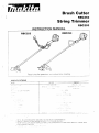
1
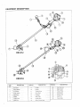
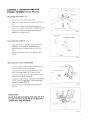
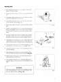
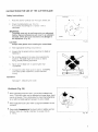
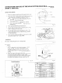
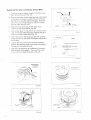
Brush Cutter
RBC252
String Trimmer
INSTRUCTION MANUAL
RBC252
Read i uies for operation z-irld instrucirons carefully
RBC253
~
- -
’
-~
Thank you very much for purchasing your MAKITA STRING T R I M M E R BRUSH CUTTER We are prclud of
and very confident in recommending our MAKITA STRING T R I M M E R B R U S H CUTTER as d result of our
extensive development and substantial knowledge and experience
Please read and understand this booklet thoroughly before operating yoiii MAKITA STRING T R I M M E R
BRUSH CUTTER In order to take advantage of its outstaridincj mrfor;?-l-ince
/
SAFETY R U L E S A N D PRECAUTIONS
Proper >afety precautions must be observed Like all power quiprnent this unit must be handled carefully
DO NOT EXPOSE YOURSELF OR OTHERS TO DANGER Follow these general rules Do not perniit others
to use this machine unless they are thoroughly responsible and have read and understood the machine manual
2 n d are trained in its operation
1 Always weal safety goggles for eye protection conforming to t h e A N S I 287 1 Safety Standard Dress
aopropriarely do not wear loose clothing or jewelry that could become caught in moving parts of the unit Safe,
siurdy nonskid footwear should always be worn Long hair should be tied back It is recommended that legs
and feet be covered to protect them from flying debris during operation
2 Inspect the entire machine for loose parts ( n u t s , bolts screws etc ) and any damage Repair or replace
as necessary before using the machine
3 DO NOT U S E any attachment with this power head other than one recommended by MAKITA Serious
i q u r v to the user or bystanders or damage to the e n g i ~ ecould result
1 Keep the handles free of oil and fuel
5 Always use the proper handle and shoulder strap when cutting
G Do not s m o e while mixing fuel or filling tank
7 Do not mix fuel in an enclosed room or near open flames Assure adequate ventilation
8 Ai??iaysmix and store the fuel in a properly marked coitainer ‘hat is approved by local codes and
crdinances for such usage
V s v e r remove the fuel tank cap while the engine is riirriir’cj
‘J
3 kever start or run the engine inside a closed room or :,JiIdii-y Fumes from the exhaust contain
dangercus carbon monoxide.
1 1 Never attempt to make engine adjustments while the uzii is running and strapped to the operator Always
make engine adjustments with the unit resting on a flat clear surface
12 Do not use the unit if it is damaged or poorly adjusted Never remove the machine’s guard
13 Inspect the area to be cut and remove all debris that could become entangled in the nylon cutting
headicutter blade. Also remove any objects that the unit may throw during cutting.
14. Keep children away. Onlookers should be kept at a safe distance from the work area, at least 50 ft.( 15m)
15. Never leave the machine unattended.
16. Do not use this unit for any jobs other than those for which it is intended as described in the manual.
17. Do not overreach. Keep proper footing and balance at all times. Do not run the unit while standing on a
ladder or any other unstable footing location.
18. Keep hands and feet away from the nylon cutting headcutter blade while the unit is in use.
19 Do not use this type of machine for sweeping away debris
20 Do not use the unit when you are tired or under the influence of medication, drugs or alcohol
21 Do not use a damaged cutting head /cutter blade If a stone or any other obstacle is hit, stop t h e engine
and check thenylon cutting head /cutter blade A broken or unbalanced nylon cutting headkutter blade
must never be used. Follow instructions for changing accessories
22 Do not store in a closed area where fuel vapors can reach an open flame from hot water heaters,
furnaces, etc. Store in a locked, well ventilated area only
I
2
-.
-
23
24
25
26
27
28
29
30
31
32
33
34
i
35
36
37
38
39
40
41
42
43
44.
45
46.
Use only replacement parts that are identical to original equipment parts when servicing the unit: these
parts are available from your dealer, The use of any other accessory or attachment inay create a
potential hazard, injury !o the user and damage to the machine.
Clean the machine completely. especially the fuel tank cap, its surroundings, and the air cleaner.
When refueling, be sure to stop the engine and confirm that it has cooled down Never refuel ,v!:&n the
engine is running or hot. When gasoline spills, be sure to completely wipe it away a n d prq)?!i'l 'Tispc?ser7f
those materials. Move at leas? 10 it. i3m) away from the fueling source and site before star!inc; ::-ISe?yirie
Stay away from other workers or bystanders (50 ft., 1 5 m ) .
W h e n approaching an operator of the machine, carefully call his attention and confirm that tihe i?ysra!or
stops t h e engine. Be careful-noi to startle or distract t h e operator causing an unsafe siiuatim.
Never touch the nylon cutting headicutter blade while the engine I S running. If it is necessdi-y ;r, &just the
protector or nylon cutting head!cutter blade, be sure to stop t h e engine and confirm that r h e 7
headicutter blade has stoppea rurning.
The engine should be turned off when the machine is moved between work areas.
Be careful not to hit the nylon cutting head/cutter blade against stones, or the ground. Unreasonably
rough operation will shorten the life of the machine a s well as create an unsafe environment io!' you and
those around you.
Pay attention to loosening and overheating of parts. I f there is any abnormality o f the machine. stop
operation immediately and check the machine carefully. If necessary, have the machine serviced by a
qualified service facility. Never continue to operate a machine which may be malfunctioning
In startup or during operation of t h e engine, never touch hot parts such as the muffler,the high-vo!tage
wire or the spark plug.
For a while after the engine has stopped, t h e muffler is still hot. Never place the machine near flammable
materials (dry grass. etc.),combustible gasses or combustible liquids.
Pay special attention when operating in the rain or shortly after t h e rain as the ground may be slippery.
I f you slip or fall to the ground or into a hole, release t h e throttle lever immediately
Be careful not to drop !he machine ar hit it against obstacles.
Before proceeding to adjust or repair the machine. b e sure to stop t h e engine and detach the spark plug
cap from the spark plug.
Before storing the machine for a long time, drain all fuel from the fuel tank ana carburzior clear1 it1e
parts. move the machine to a safe place, a n d confirm that t h e engine has cooled down.
Make periodic inspections to assure safe and efficient operation, If you need professional inspection of
your machine, please contact your nearest Makita Factory Service Center or authorized dealer.
Keep the machine well away from fire or sparks.
Warning: The cutter area is dangerous while the machine is coasting to a stop.
Don't try to tackle a big job with an undersized machine. Use this machine only for trimming; use a lawn
mower for large areas.
Wear a dust m a s k in dusty work conditions.
Wear hearing protection for extended periods of use, and any time the noise is uncomfortable.
Keep guards and protectors in place and in working order.
Never operate this machine while it is turned upside-down or w h e n it is at an extreme angle.
CAUTION!
CAUTION!
CAUTION!
WHEN MIXING GASOLINE WITH TWO-CYCLE ENGINE OIL, USE ONLY GASOLINE WHICH CONTAINS NO
ETHANOL OR METHANOL (TYPES OF ALCOHOL), THIS WILL HELP TO AVOID POSSIBLE DAMAGE TO
ENGINE FUEL LINES A N D OTHER ENGINE PARTS.
.
'
SAVE THESE INSTRUCTIONS.
3
-
EQUIPMENT DESCRIPTION
*
”
RBC252
I
RBC253
~
ITEM
NO.
1
3
#
-5
7
8
FuelTank
I
Air Cleaner
___
__
Recoil Starter
--
,
-
1
Spark Plug
.. ---,
----
-
_.
-
i Holder Case
T<TaT&ip
1 ITEM NO.
-
~
DESCRIPTION
Hanger
. - ~
-
9
10
13
~~
14
-
~
-
-
15
16
18
~
___
-
~
1
Protector
-
--
Gear Case
--
23
--
__
___
~
-~
24
-- - --~~
DESCRIPTION
i
Fuel Filler
Cap .
~
--Starter
__ Knob
Primer Pump
Choke Lever
I
21
22
__
_.
.
Handle Joint
Nylon Cctiing Head
-
-
Drive Shaft
-
-
ITEM NO.
20
~
Handle _-Throttle Lever
11
T S T O P Switch
6 r e l f f uM- -
-
I
I
2
4
DESCRIPTION
I
-
7 . -
----
Exhaust Pipe
_-
-
25
Waist Pad
26
Cutter Blade
ASSEMBLY INSTRUCTIONS FOR
STRING T R I M M E R (Model RBC253)
Mounting t h e handle (Fig. 1 )
Attach the handle to t h e drive shaft
2 Install the handle joint on the handle as shown in
Fig 1
3 Insert the installation bolt M6x45 through the
holes in the handle a n d attach t h e flange nut M 6
4 Adjust the handle to the desired position a n d
tighten the installation bolt
1
-
,
-
...
Fig 1
-
Gear case
I
Installation bolt M6x20
Mounting t h e protector (Fig. 2)
1 . Install the clamp on the drive shaft so that the
,
projection of the clamp is inserted into the
opening between the gear case a n d the drive
shaft.
2. Attach the protector with two installation bolts
M6x20.
Ciamp
,
I
i
Protector
Fig. 2
Mounting t h e nylon cutting head
Turn the machine upside down so that you c a n
easily install t h e nylon cutting head.
2 . Insert t h e hex wrench through t h e hole in the
back of the g e a r case (Fig. 4) a n d turn the
tightening washer until it is locked with the hex
wrench (or the shaft is locked).
3. Using t h e socket wrench, remove the left-handed
nut (by turning it clockwise). Also remove the
tightening washer (Fig. 3 ) .
4. S c r e w the nylon cutting h e a d onto the shaft
(Fig. 4).
1
Fig. 3
IMPORTANT!
READ THE INSTRUCTIONS FOR U S E O F THE
NYLON CUTTING HEAD (PAGE 17) BEFORE
OPERATING THIS MACHINE.
Fig. 4
5
TProttle wire
io throttle lever
STEP 1
Throttle wre ano
Flcj 9
Mounting the handle and connecting the throttle wire a n d switch cords.
1 klatch the protrusions on the handle joint 10 the slot in the underside of the handle and tighten h e four
2
3
4
5
6
6
socket head bolts M 5 evenly to secure the handle (Fig 5,6)
Connect the throttle wires and firmly close the cable joint (as shown in 3 steps in Fig 7 )
Note Squeeze the throttle lever to make sure that the throttle wire moves smoothly
Connect the switch cords to the two cords from the engine by inserting one into the other
Wrap the waist pad around the drive shaft so tnat the hanger will protrude through the slit in the waist
pad and the throttle wire and cords w1'I also be wrapped under the waist pad (Fig 8 )
Secure the throttle wire with the w e clip as shown in the figure for easy oDeratioi1 (Fig 9)
Cover the throttle wire and swtct? cords w t h split tubing (Fig 10)
Notes It IS easier to instdl ihe split tcrbing if the bullet connectors are partially pished into the
motor cover to rernove sixk fiom the wires
ASSEMBLY INSTRUCTIONS FOR
Gear case
B R U S H CUTTER (ModelRBC252)
Installation bolt M6x20
Mounting t h e protector (Fig. 11)
1.
Install the clamp on the drive shaft so that t h e
projection of the clamp is inserted into the
opening between the gear case and the drive
shaft.
Protector
2. Attach the protector with two installation bolts
M6x20.
Fig. 11
Mounting the cutter blade (Fig. 12,13)
1 . Turn the machine upside down so that you can
easily install t h e cutter blade.
2. Insert the hex wrench through the hole in the
back of t h e gear case and turn t h e tightening
washer until it is locked with the hex wrench
(or the shaft is locked).
3 . Using the socket wrench, remove the left-handed
nut (by turning it clockwise). Also remove the
tightening washer.
4.
Mount the cutter blade onto the shaft so that the
guide of t h e support washer fits in t h e arbor hole
in the cutter blade. Install the tightening washer
and secure the cutter blade with the nut.
(Tightening torque: 130-230 Kg-cm,l 15-200 in-
r--
Ibs).
NOTE:
Always wear gloves when handling t h e cutter
blade.
WARNING:
T h e cutter blade s h o u l d be installed firmly
a n d securely. (Fig. 14)
If t h e g u i d e of t h e s u p p o r t w a s h e r d o e s n ' t fit
in t h e a r b o r hole in t h e cutter blade. t h e b r u s h
cutter will m a k e violent vibration. It not only
s h o r t e n s t h e m a c h i n e life, b u t m a y also
allow the cutter blade t o l o o s e n a n d fly off.
Failure to install t h e blade correctly can c a u s e
s e r i o u s injury.
7
.
!FA PO R T A N T !
R E A D THE I N S T R U C T I O N FOR
S
USE O F T H E
B R U S H C U T T E R B L A D E (PAGE 15) BEFOFIE
OFERATING THIS MACHINE.
HE
~
I
P R E P A R I N G FOR OPERATION
Fuel a n d oil mixture
This product is powered by a two-cycle e n g i n e and requires pre-mixing gasoline and two-cycle engine 011
Inspect the fuel tank and f i l l with clean, fresh fuel and oil of the proper rrtxture to assure the longer life of the
tool Use the following mixed gas
Gasoline Genuine Makita Two-cycle engine oil = 50 1 or
Gasoline Other manufacturer's Two-cycle engine oil = 25 1 recommended
____
-.
____- - __
- - .
FOR CALIFORNIA REGULATION:
THIS EQUIPMENT IS CERTIFIED TO OPERATE ON GASOLINE + TWO-CYCLE ENGINE OIL
~
WHEN MIXING GASOLINE WITH TWO-CYCLE ENGINE OIL,USE ONLY GASOLINE WHICH CONTAINS NO
ETHANOL OR METHANOL (TYPES OF ALCOHOL). THIS WILL HELP TO AVOID POSSIBLE DAMAGE TO
ENGINE FUEL LINES A N D OTHER ENGINE PARTS.
DO NOT MIX GASOLINE A N D OIL DIRECTLY IN THE FUEL TANK.
IMPORTANT: Failure to follow groper fuel mix instructions may cause damage to t h e engine.
CAUTION:
1 . When preparing fuel mixture, mix only the amount needed for the job you are to do. Do not use fuel
mixture that has been stored longer t h a n tbvo months. Fuel mixture stored longer than this will cause hard
starting and poor performance, I f fuel mix has been stored longer than this time, it should be removed
and replaced with a fresh mixture.
2. Never- f i l l the fuel tank to the very top
3. Never add fuel to the tank in a closed, unventilated area.
4 Do no: add fuel to this unit close to an open fire or sparks
5. Be sure to wipe off spilled fuel before attempting to start the engine
6. Do not attempt to refuel a hot engine.
Check points before operation
1 . Check for loose bolts, nuts and fittings.
2. Check the air cleaner for dirt. Clean t h e air filter of all dirt, etc. before operation
3. Check to be sure that protector is securely in place.
REFUELING
Use Oil-gasoline mixture for fuel as noted in "Fuel and Oil
Mixture" on previous page
Always s h u t off the engine and allow it to cool before refueling.
Thoroughly clean the area around the fuel filter cap, to prevent dirt from getting into the fuel tank.
Unscrew the fuel cap and f i l l the tank with fuel, then screw
on the fuel filler cap tightly(EdT. /'3,'..
-
I
Wipe off any spilled fuel before starting. and check for leakage
1
Figl 5
Check for fuel leakage while refueling and during operation
If fuel or oil leakage is found, do not start or run the engine
until the leak is fixed and any spilled fuel has been wiped
away.
Avoid skin contact with mineral oil products. Do not inhale
fuel vapor. Always wear protective gloves during refueling.
Change and clean protective clothing at regular intervals.
Take care not to spill either fuel oi oil in order to prevent soil
contamination (environmental protection) Clean the brush
cutter or string trimmer immediately after fuel has been spilt
Avoid any fuel contact with your clothing. Change your clothing instantly if fuel has been spilt on it (a danger to life)
Inspect the fuel cap at regular intervals making sure that it
securely tightened.
1
Figl 6
IS
Select bare ground for fueling and move at least 10 feet
(3m) from fueling spot before starting the engine(Fy, &),
Never refuel in closed rooms. Fuel vapors accumulate at
ground level (risk of explosions).
Only transport and store fuel in a container approved for
gasoline. Make sure the stored fuel is not accessible to children.
WARNING!
Gasoline is extremely flammable fuel Use extreme caution
when handling gasoline or fuel mix. Do not smoke or bring
any fire or flame near the fuel(FA?. /yI4
=
.
Figl 7
9
ENGINE STARTING A N D STOPPING
PROCEDURES
Starting w h e n t h e e n g i n e is cold
Use the following procedure when the engine is cold 01 after It
has beer, stopped for longer than 5 minutes. or aft;.: f1~ir.I has
oeen added to !he engine.
1 . S!ide t h e stop switch away from t h e 'STOP
(Fig. 17.18).
2. Gently push on the primer p u m p repeated!\/ 7 1 Q times)
until fuel enters the primer p u m p (Fig. 19)
3 Close the choke lever fully by mown3 it to tiic
, a qposition (Fig. 19:i
4. Lock the throttle lever in the "start"position 5s tJl!cws:
REX252 (Fig. 13)
Squeeze the throttle lever fully
I)
Push the lock button while releasing thi! throttle lever
ii)
RBC253 (Fig. 20)
i ) . Squeeze the throttle lever fully.
ii).
Hook the lock fin to the notch in the throttle lever
while releasing the throttle lever.
5. Lay the machine in a clear area Be sure t h s cutting line or
blade canso: cmtact the ground or any obsti-ircrion
Hold the d:ive shaft or the grip with one haat! and give
severa! strong pulls to the starter using the other hand.
6. After t h e engine has started. open the choKC lev?r fully
by c w n g it gradually to :he o position.
7. Release the throttle lever fully.
Note: The throttle lever is unlocked by s w e
s I I cj I i t i v
~
~
R e s t a rt I ri g
1
i ITm ed i at
0-
SIOD
,
Postion
Stop switch
I Start
Position
Throitie level
Lock button
Lock off lever
~
w
Fig. 18
e I y aft e r t h e o! n y i i i P h a s s t o 13ped .
Slide the stop switch away iron; tne STOP ucsition
(Fig 17 18)
2 Gently p u s h on the primer p u m p repeatedly 1 7 - 10 times)
until fuel enters the primer p u m p (Fig 19)
3 Leave the choke lever in the oDen
positiorl (Fig 19)
4 Leave the throttle lever fully released
5 Lay the machine in a clear area Be sure the cutting line or
blade cannot contact the ground or any obstruction Hold
the drive shaft or grip with one hand, and give several
strong pulls to the starter using the other hand
Choke lever
Fig. 19
/
CAUTION:
Never operate the engine at high rpm without load. With t h e
throttle lever fully squeezed and n o load, the engine rpm
will be very high which could have a n adverse effect o n t h e
life of t h e engine.
Stopping
1 . Release the throttle ievei fully
2 When t h e engine rpm has lowered, p u s h the stop
switch to the "STOP" position The engine w11 stop
Lock fin
\
Fig. 20
10
CORRECT HANDLING OF THE MACHINE
I
i-
...
..
~-
~-
Fig 2 2
Fig. 21
Attachment, adjustment a n d d e t a c h m e n t of t h e s h o u l d e r s t r a p
Attachment
Place the strap hook into the hanger which
I S located
on the shaft between the grip and the handle
Adjustment
Adjust the strap length so that the nylon cutting head / blade VJIII be kept parallel to the ground (Fig 21)
i
Detachment (NORMAL)
Remove t h e strap hook from the hanger.
Detachment (EMERGENCY)
In an emergency, release the throttle lever, firinly pull the re1;a.k iJelt upward and dei?,c? the machine fror
( F I G 22) Be extremely cautious to maintain control of t h e maci- r i at this time Do not allon the machine i
defixted toward you or anyone in t h e work viciixtv
!J-
WARNING:
Failure to maintain complete control of t h e machine at all times could result in serious bodily injtiry or
DEATH.
Keep cutting attachment below waist level.
___
_-
Notes:
The shoulder strap has a quick release system
Check that the hook is assembled a s shown in
Fig. 23. If it is not, remove it and reassemble it
as shown (Fig. 23).
Hook
Release Belt
Strap
I
~-
_-
Fig 2 3
-
Handling t h e machine
1.
Hang the machine on the right side of your body
2
Squeeze the throttle lever to increase the rotational speed Release the throttle lever -md the erigir'e rvill
run at idle (low speed) Use a rotational speed suitable for the grass being cut I f t I D roiatiJnal speed is
excessively low grass may become lammed in the nylon cutting headicutter blade
3.
During grass cutting. firmly hold the machine to allow easy, controlled handling
4.
Never strike or tap objects with the nylon cutting headicutter blade
Idle a d j u s t m e n t
The nylon cutting head should not run when the throttle
lever is fully released If necessary. adjust the idle rpm
using the idle adjusting screw (Fig 24).
I
Idle ad!ilsiing screw
Fig 24
USE THE PROPER PROTECTOR FOR THE NYLON CUTTING H E A D
OR CUTTER BLADE A S S H O W N B E L O W
_ -
STRING T R I M M E R RBC253
N y lor1
c U "i r q head
B R U S H CUTTER RBC252
Protec!or for nylon cutting head
Star blade
Protecroi
i,jr P i l t a i
cutter blade
Grass-pasture
Fig 25
Fig 26
1
To meet the applicable safety provisions, only t h e tool/protector combination as indicated in the table must be
used.
Be sure to use genuine MAKITA cutter blade or nylon cutting head.
CAUTION:
- .
T h e appropriate protector m u s t always b e installed, for your own safety a n d in order
t o comply with accident-prevention regulations.
Operation of t h e e q u i p m e n t without t h e protector being in place is not permitted.
12
-
DAlLY CHECK-UP AND MAINTENANCE
cover
,
Fig. 27
06 mm
(0024'
I
-
Sponge element
FIY 28
- 0 7 mm
- 0028")
x
I
I
I
Fig. 29
Fig. 30
1 . Before operation, pay particular attention to the tightness of the nylon cutting head. Re-tighten the , ~ y I c : ~
cutting head if necessary (every 8 h o u r s or daily).
2. Check for clogged cooling air passage and cylinder fins. Clean them if necessary (every 8 hours or da!ly)
3. Clean the air cleaner every 8 hours or daily. using the following procedure:
i). Remove the air cleaner cover. Clean the sponge element and remove any excessive dust or dirt
4.
5.
6.
7.
8.
9
10
adhering to the cleaner (Fig. 27 and 2 8 ) . A clogged air cleaner may make it difficult or impossible to
start t h e engine or to increase the engine rotational speed
ii). Re-install the sponge element around the ribs of the air cleaner case.
Check the spark plug every 8 hours or daily.
The gap between the two electrodes of the spark plug should be 0.6 to 0.7 m m (0.024"to 0.028").
If t h e gap is too wide or too narrow, adjust it.
If the spark plug is clogged with carbon or fouled, clean it thoroughly or replace it (Fig. 29).
Apply grease (SHELL ALVANIA No. 3 or equivalent) to the gear case through the grease hole every 30
hours (Fig. 30).
Clean the muffler exhaust port every 50 hours or monthly.
Check the fuel filter. If clogged, replace it with a new one every 50 hours or monthly.
Replace the fuel lines every 200 hours or yearly.
Overhaul the engine eyery.200 hours or yearly
Replace the packing andgaskets with new ones every time the engine is reassembled
13
STORAGE
'
When storing the machine for a icng time drain the fuel from the fuel tank and cdrbLretor as follows
1 Drain all fuel from the fuel tank Gently push on the primer pump repeatedly i i n t r l all fuel IS expelled out of
the primer p u m p Properly dispose of the fuel in accordance with all local laws
2 Remove the spark aluy and add a few drops of oil into the spark plug hole Then pull the starter geMy to
assure that d n oil ;ilm coats the engine inside, then insert and tighten the S D k~ d u g
3 Clear or olow any dirt or d u s t from the nylon cutting head and engine housing wpe them with an
oil-immersed cloth and store the machine in a dry location
REASSEMBLY 1NSTRUCTlONS
B r u s h Cutter RBC2.52 and String Trimmer RBC253
i
Reassembling t h e drive s h a f t and t h e engine.
The shaft and the engine on this machine have been
assembled in the factory. If you remove the shaft
(example, for maintenavce) carefully reassemble it as
shown be I ow:
1 . Loosen the screws M5x18 and insert the drive
shaft into the holder case (Fig. 31).
Note:
i ) . Always inserr the drive shaft into the holder
case fully (approx. 60mm; 2-3/8"). If the inner
shaft resists full insertion of the drive shaft,
t r y to insert it again while slightly rotating the
siqport washer on the gear case.
ii).
5 ~ 2caiitio~isnot to allow the switch cords to
!:;: ;jinih;d between the holder case and the
gt1i end.
2. After making scire that the drive shaft is installed
fully and properly. tighten the screws M5x18 to
secure the drive shaft.
Connecting t h e wires (String Trimmer only RBC253)
1 . Insert the nipple of the throttle wire through the
square hole in the grip until it fits into an inner
square hole in the moving part which is inside the
grip. The nipple should move when the throttle
lever is squeezed (Fig. 32).
Note: Squeeze the throttle lever to make sure
that the throttle wire moves smoothly.
2. Connect the two switch wires to the engine wires
by inserting one into the other.
3. Cover the throttle wire and switch wires with split
j
I
~
I
I
I
~
Hoidsr case
Fig 31
i-
1
Nipple of throttle wire
.
Fig. 32
tubing.
_Note:
It is easier to install the split tubing if the bullet
connectors are partially pushed into the motor
cover to remove slack from the wires (Fig. 33).
Fig. 3:
14
INSTRUCTIONS FOR USE OF THE CUTTER BLADE
safety instructions
1.
Read this section carefully and thoroughly before use
2
Check the blade before use (Fig 34)
If you notice any damage to it, replace it with a
new blade.
IMPORTANT:
The blade m u s t only be resharpened by an authorized
facility. Manual resharpening will result in an unbalanced blade, which will cause vibrations a n d damage to
t h e equipment. (Fig. 35)
CAUTION:
Always wear gloves when handling the cutter blade.
A
Be:.:
r
Cracks
Fig 34
3. Wear appropriate clothing and protectors
4 . Always stop the engine before inspecting t h e blade or
replacing it.
5. Do not allow anyone in the area while operating the
machine. The blade might send stones or debris
flying, possibly harming bystanders.
6 . Never use the blade with its speed higher than
10.000RPM.
7 . Increase the cutter head speed to approx. 6.000RPM.
Low speed (under 4,000RPM) causes inefficient
cutting.
Installation
See page 7 . (Mounting the blade)
Kickback (Fig. 36)
When operating the brush cutter, uncontrolled kickback may
occur. The brush cutter may be deflected with great force, creating risk of injuries. This is particularly the case when attempting
to cut within a blade segment between 12 and 2 o'clock.
Never apply t h e brush cutter within a segment between 12 and
2 o'clock.
Never apply- t
the brush cutter to solids, such as
bushes, trees, etc., having a diameter in excess of 3 cm
(1 118 in.).
Fig. 36
15
Kickback Prevention
To avoid kickbacks, observe the following:
Easy cutting with almost no kickback is possible within a blade segment between 8 and 1 1 o'clock (Fig 37)
Operation within a blade segment between 12 and 2 o'clock
presents severe hazards, especially when using metal cutting
tools.
Cutting operations within a blade segment betweep 1 1 and 12
o'clock, and between 2 and 5 o'clock, m u s t only be performed
by train& and experienced operators, and then only at their
own risk.
I
Fig. 37
CUTTING TOOLS
Employ only the correct cutting tool for the 1 o b . M
Nylon Cutting Head:
I
1
Exclusively designed for cutting along walls. fences. grass
edges, trees, posts, etc. (supplementing the grass mower).
S t a r Blade:
\
For cutting thick materials, such as weeds high grass, bushes,
shrubs, underwood, thicket, etc (max 2 cm or 314 in) Perform
t h i s cutting work by swinging the brush cutter eveniy in halfcircles from right to left (similar to using a scythe)
Maintenance instructions
Fig. 38
Before commencing work, check the caridition of the cutter,
protective devices and also the shoulder strap Particular
attention should be paid to the cutting blades which must be
correctly sharpened (Fig. 38)
Turn off the engine and remove spark plug connector when
replacing or sharpening cutting tools, and also when cleaning
the cutter or cutting tool.
Use the blade cover when you transport or store the brush
cutter, to prevent injury and damage to the blade (Fig.39).
16
I
Blade cover
i
~
INSTRUCTIONS FOR U S E OF THE NYLON CUTTING HEAD (Model WBC253)
*
(BUMP & FEED BF4)
I
Safety Instructions
1
2
Read this section carefully and thoroughly before use
Check the nylon cutting head carefully before each use
If you notice any of following, replace the worn or
damaged parts with new ones immediately (Fig 40)
Dents appear on the knob head
The housing (cover) is damaged or cracked
The "Limit marks (notches)" on the cover have
disappeared
Wear appropriate clothing and protectors
4 Always stop the engine before inspecting the cutting
head or replacing the nylon cord
5 Do not allow anyone near the operation area The
cutters might send stones or debris flying, possibly
harming bystanders
6 Never use the cutting head BF4 on tools with a cutter
head speed higher than 10,000 R P M
3
i
installation
See page 5 (Mounting the nylon cutting head)
2
r
Increase t h e cutter head speed to approx 6 000
RPM Low speed (under 4,000 RPM) causes
inefficient cutting Use the tip of the nylon cord
(shaded area shown in Fig 41) for more effective
cutting.
When t h e nylon cord wears down (becomes short),
decrease the engine speed to under 4,000 RPM
and tap the knob of the nylon cutting head against
the ground to advance the nylon cord (Fig 42)
Parts Breakdown
I
I
Fio.
., 43
__ -
Fig 40
r-
j
0 pera ti o n
1
'===
1.
1
~
_
_
_
_.
Fig 4 1
_r 3
'
I
,
Fig. 42
17
Replacing t h e nylon cord (Bump & Feed BF4)
1 . P r e s s the homing latches inward to lift off the cover;
then remove t h e spool (Fig. 44).
2. R u n the new nylon cord through t h e hole in the center
of t h e spool. a n d pass o n e e n d of the cord through
[he notch into the other side of the spool. Allow one
3.
4.
5.
6.
7.
e n d of t h e cord to extend about 3" ( 8 0 m m ) further
than the other e n d (Fig. 45).
Wind both e n d s firmly around the spool in t h e
direction of the head rotation.(Fig. 46).
Wind all but about 4" (100 mm) to 6" (150 mm) of t h e
cord, leaving t h e e n d s temporarily hooked through a
notch on the side of the spool (Fig. 47).
Mount t h e spool in the housing so that the grooves
and protrusions on the spool are aligned with those in
the housing.
Unhook the e n d s of the cord from their temporary
position a n d feed the cords out through the eyelets in
t h e side of t h e housing (Fig. 48).
Align the protrusions on the underside of t h e cover
with the slots of the eyelets. Then push the cover
firmly onto the housing to s e c u r e it (Fig. 49).
Fig $4
1
3" (80 m m )
-
Notch
I
I
1_1
E
i
i
I
1
I
i
Fig 45
i
1
Model RBC253
wind cord in
LH direction
4" (100 m m )
to 6" i 1 5 G mi;?!
i
I
/
/'
I
Fig. 47
Fig. 46
1
,
Protri
~~~
Fig. 48
18
Fig 49
Emmision Control Warranty Statement
YOUR WARRANTY RIGHTS A N D OBLIGATIONS
The California Air Resources Board arid Makita U.S.A..Inc. are pleased to explain the emissiori zo!i:rcl warranty
on your 1995 and later utility and/or lawn a n d garden equipment engine. In California.neit utility arid lawn and
garden equipment engines must be designed, built and equipped to meet the State's strqent anti-smog standards. Makita U.S.A.,Inc. must warrant the emission control system on your utility and/or lawn and garden
equipment engine for the periods o f time listed below provided there has been no abuse. neglect or i/71proppr
maintenance o f your utility and/or la-wn ana garden equipment engine.
Your emission control system includes parts such as the carburetor or fuel injection systems the ignition system
and the catalytic converter Also included are the hoses and connectors and other em/ssion-re/ale=l
assemblies
Where a warrantable condition exists Makita U S A , Inc will repair your utility and/or iawr and gaicleii equipment at no cost to you including diagnosis parts and labor
MANUFACTURER'S WARRANTY COVERAGE:
The 1995 and later utility and/or lawn and garden equipment engines are warranted for two years I+' any em/ssion-related par? on your engine is defective, the part will be repaired or replaced by Makita U S A lnc
OWNER'S WARRANTY RESPONSIBILITIES:
A s the utility and lawn and garden equipment engine owner, you are responsible for the peiformance o f the
required maintenance /isfedin your owner's manual Mak/ta U S A lnc recommends that J'OLI i e h n dI receipts
covering maintenance on your utility and/or lawn and garden equipment engine, but Makita U S A I'Jc cannot
deny warranty solely for the lack o f receipts or for your failure to ensure the performance o Laii scheduled main-
tenance
A s the utility and/or lawn and garden equipment engine owner you should be aware however that Vakita
U S A , lnc may deny you warranty coverage i f your utility and/or lawn and garden equipment engine or a part
has failed due to abuse, neglect improper maintenance or unapproved modifications
You are responsible forpresenting your utility and/or lawn and garden equipment engine to a Makita U.S.A., Inc.
service center as a problem exists. The warranty repairs should be completed in a reasonable time. not to
exceed 30 days.
I f you have any questions regarding your warranty rights and responsibilities,you should contact a Makita
FactoryService Center Manager nearest you. A list o f the Factory Service Centel-locations and phone numbers
is provided below for your convenience.
19
LllMlTED WARRANTY
- California Only Makita U S A Inc a distributor of utility and lawn and garden equipment in the U S , warrants to the owner of
1995 and later utility and/or lawn and garden equipment engines that the engine ( 1 ) has been designed built
apa equipped at the time of manufacture so as to conforrn with the applicable iegulations of the California Ai,
Resources Board and (2) is free from defects in materials and workmanship which may cause it to fail to c m form with those regulations as applicable according to the terms and conditions stated below
WARRANTY PERIOD
The warranty period begins on the date which the utility and'or lawn and garden equipment engine is delivered
!o t h e original retail purchaser and ends two years after that date During this two year period Makita U S k
Inc warrants to the original retail purchaser and each subsequent purchaser that the engine is free from defect
in material and workmanship that can cause the farlure o f a warranted emission-related part
WHAT IS COVERED U N D E R THIS WARRANTY
\
Repair and/or replacement of any warranted emission-related part will be performed at no charge provided ihe
work is performed at an authorized warranty station There will also be no charge for any diagnostic labor perrxmed at an authorized warranty station which leads to the determination that a warranted emission-related Dart
I S defective
A n y warranted part which is not scheduled for replacement as required maintenance, or which IS scheduled cnly
tor regular inspection to the effect of "repair or replace as necessary" shall be warranted for the warranty peri3d
A n y warranted part which is scheduled for replacement as required maintenance shall be warranted for t h e p w oc of time up to the first scheduled replacement of that part This warranty shall apply only towards the r e m l r
replacement, and/or adjustment of the component parts listed below
EMISSION-RELATED PARTS COVERED UNDER THIS WARRANTY
1
Fuel Metering Systems
(a) Carburetor and its internal parts
(b) Air cleaner plate
(c) Air cleaner case
(d) Air cleaner element
(e) Fuel filter
2. Ignition Systems
(a) Spark Plug
(b) Flywheel Magneto
(c) Ignition Coil
3. Other Miscellaneous Items Used in Above Systems
-
(a) Fuel Hoses
(b) Sealing Gaskets
If it IS determined by an authorized warranty station that other engine components have been damaged due to
the failure of a warranted emission-related part during the warranty period, Makita U S A , Inc will repair and/or
replace t h e necessary components
*
.
WHAT IS NOT COVERED U N D E R THIS WARRANTY
Tills ivarrai?ty does not cover any emission-relatea part <>vITich
m?l:i.J!i
c s , t d s , or 1s daniageci ' : w t3 a i t ~
c;ns and/or modifications such as changing. adding. or rerriov:r it4 :)dl I <
V!hc?ii
;f.ji'S
an engine is being serviced under warranty.
M2.kii2
of warranty stations shall not be liable for any loss of
U S k !nc:
.
3':
.JSC LJ! ' ' ~ ,;!IY
?
ny of I!S authorized dealers. r:'
,
my damage to SQ'
!inle si inconvenience
s limited warranty aiso does not apply to any emi5siov :da:e(; ;;at ~vhiclimaifui:c:ions. tails. ' J r : ja3:71,1
-jL.e!o failure to follow the maintenance and operaring \ns;rlJctio:?'<
q!ec;fiad in the i 995 and iater Oi..iii?r s
h.1 a n u a I i n c I u d i n g :
,';*
a ) lr7p;per or irradeqtiate maintenance o f a r ' y v
? ) Improper installaiion. adjustment. or repair r j f !re
performed by a fac!ory authorized warrant$; :;t,?raivi
ission-reiateu part
:.jii
Failure to use recommended fbel a s speciiiec ,r: t f i ? ?XI5 an<J la:er 0:Ilr:er's Manual.
. d ) Repairs and diagnosis performed outside of an atitnor~zed'n arrmtv sietion.
iise 3i parts which are not authorized by P
5)
MAINTENANCE S C H E D U L E
Tile zngine owner is res?onsible for having all x h e d i i l e d inspectlor) and maintenance services perjrJiTnesi
intervals specified in tna 1995 and later Owner-5 liilani,ai a n d to r3:ain records of these services as ha>Jin2
performed. These recorm should be transferred to zach sGoseq.i-?rria v n e r of the engine. PAakita U.S.4
c,?rino! deny a claim so13ly because there are no records of schedui3d maintenance; hoivever. a warrai:;,;]
ITS)/3)' denied if the fai1dr.e to perform the sch
deci r:ia!ii;anaric~ !-:owever,a warranty claim may by de
it?? f?i!Lireto perform thz xheduled maintenai
m c inspection !esL:;iad in the failure oi a warranted emis=
r?ia!c?3 part. A s a mirilii;un1, :!le engine owner , ? rssyinsibie foi !!isscheduled inspection a n d maints;^lar-,-.
described below which are based on the procediires described in the Owner's Manual
PROCEDURE
Gneck all n u t s ci! 131:s I i d tighten 5
a +
Cneck air passages ancl engine cylinuer :is : , h 3 q IC,
Remove all obsti uctloiis as liecessar\
Clean the air cleaner
Check t h e spark plug Clean and adjust it i t riecessar)
Check the muffler exhaust port Clean it i f necessary
Check the fuel filter If clogged replace it with a new fiIt9r
Replace fuel lines
Overhaul the engine
Replace t h e packings and gaskets
f
-1
Every 8 hours o f use c ; daily
Every 8 hours of use or Gaily
Every 50 hours of use si rnoiith ,'
Every 50 hours of use or monthly
Every 200 hours of use or annually
Every 200 hours of use or annually
Every time t h e engine is reassembled
'1
REPAIR A N D R E P L A C E M E N T O F ERillSSIQN-RELATED P A R T S
/
I S reccximericlerf thai Sniy engirie replacement parts which have beer aLtiic;r!zer: ?r-ifJ approwcl by Makita
U . S A . , Inc. ~ t i : ~ ?le
a ~~~~J s eini it h e performance Df a n y warranty maintenance or i , < ~ : ~
of: emission-related
s
oarts These :epi?ce;riarit parrs will be provided at no charge i f the par! is Sill1 L I P I : '~. v~c i m n t y
It
HOW T O FILE A WARRANTY CLAIM
A N D W H E R E T O G E T WARRANTY SERVICES
3
r'+'tf,?stil,l?k!ta Factory Service Cc-rter Manager to rJetern?i:ie :ii.:; in;::?sr'?telocation where the
r : ~ ~ ) : ' y Ser'xes are io b e performed
A list of the Factor] S e r u c ~::?-:e:.lilctitions and p!ione ncim-
c e l ~ vior
~ y o u r convenience
1553 Rose~iilleR 3 S k E
North Hiynlands' C 4 95660
(916)331-621 1
333 Littlefieid A v ?
S S a n Francisc? 2;. '?@%I
(4151 875-10132