1
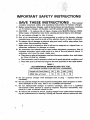
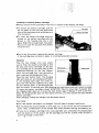
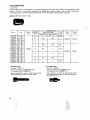
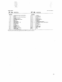
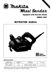
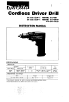
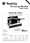
\-
n
I
12.7 mm (1/2")
12.7 mm (1/2")
MODEL 6900D
MODEL 6900DW
With Fast Charger
INSTRUCTION MANUAL
SPECIFICATIONS
Model 6900D
Capacities
Impacts per minute
Bolt size
Square drive
M8 - M 1 4 15/16" - 9 / 1 6 " )
No
ME
- M 1 0 15/16"
load speed IRPMI
High
1,500
1
LOW
,,300
9 6 V
~
I
At high speed
1 , 0 0 0 kg.cm 172 ft.lbs1
Note 1
318")
12 7
mm
2,000
1,500
11/2"l
I
1
nr
Overall
length
A t low speed
400 kg.cm 129 tt.lbsl
Note 2
Model D C 9 1 0 0
Charging time
I
A t low speed
Tightening torque
Battery Canridge 9000
Voltage
A t high speed
High tensile bolt
Standard bolt
I
2 2 6 mm
18-718")
I
1 . 7 kg
13.7 lbsl
Fast Charger
Input
I
Net
weight
AConlv50Hz-60Hz
OUtPUt
I
D C 9 6 V
Note 1. After tightening high tensile bolt M12 for E seconds while using a fully charged battery cartridge.
Note 2. After tightening high tensile bolt M10 for E seconds while using a fully charged battery cartridge.
* Manufacturer reserves the right to change specifications without notice.
* Note: Specifications may differ from country to country.
IMPORTANT
SAFETY INSTRUCTIONS
(For All Tools)
WARNING: WHEN USING ELECTRIC TOOLS,
BASIC SAFETY PRECAUTIONS SHOULD ALWAYS BE FOLLOWED TO
REDUCE THE RISK OF FIRE, ELECTRIC SHOCK, AND PERSONAL INJURY, INCLUDING THE FOLLOWING:
READ ALL INSTRUCTIONS.
1. KEEP WORK AREA CLEAN. Cluttered areas and benches invite injuries.
2. CONSIDER WORK AREA ENVIRONMENT. Don't use power tools in damp
or wet locations. Keep work area well lit. Don't expose power tools t o rain.
Don't use tool in presence of flammable liquids or gases.
3. KEEP CHILDREN AWAY. All visitors should be kept away from work area.
Don't let visitors contact tool or extension cord.
4. STORE IDLE TOOLS. When not in use, tools should be stored in dry, and high
or locked-up place - out of reach of children.
5. DON'T FORCE TOOL. It will do the job better and safer at the rate for which
it wasqntended.
6. USE RIGHT TOOL. Don't force small tool or attachment t o do the job of a
heavy-duty tool. Don't use tool for purpose not intended.
7. DRESS PROPERLY. Don't wear loose clothing or jewelry. They can be caught
in moving parts. Rubber gloves and non-skid footwear are recommended
when working outdoors. Wear protective hair covering t o contain long hair.
8. USE SAFETY GLASSES. Also use face or dust mask if cutting operation is
dusty.
9. DON'T ABUSE CORD. Never carry tool by cord or yank it t o disconnect from
receptacle. Keep cord from heat, oil, and sharp edges.
IO. SECURE WORK. Use clamps or a vise to hold work. It's safer than using
your hand and it frees both hands t o operate tool.
11. DON'T OVERREACH. Keep proper footing and balance at all times.
12. MAINTAIN TOOLS WITH CARE. Keep tools sharp and clean for better and
safer performance. Follow instructions for lubricating and changing accessories. Inspect tool cords periodically and if damaged, have repaired by authorized service facility. Inspect extension cords periodically and replace if
damaged. Keep handles dry, clean, and free from oil and grease.
13. DISCONNECT TOOLS. When not in use, before servicing, and when changessories, such as blades, bits, cutters.
-
2
I
14. REMOVE ADJUSTING KEYS AND WRENCHES. Form habit of checking t o
see that keys and adjusting wrenches are removed from tool before turning
it on.
15. AVOID UNINTENTIONAL STARTING. Don't carry plugged-in tool with finger
on switch. Be sure switch is OFF when plugging in.
16. OUTDOOR USE EXTENSION CORDS. When tool is used outdoors, use only
extension cords intended for use outdoors and so marked.
17. STAY ALERT. Watch what you are doing, use common sense. Don't operate
tool when you are tired.
18. CHECK DAMAGED PARTS. Before further use of the tool, a guard or other
part that is damaged should be carefully checked t o determine that it will
operate properly and perform its intended function. Check for alignment of
moving parts, binding of moving parts, breakage of parts, mounting, and any
other conditions that may affect its operation. A guard or other part that
is damaged should be properly repaired or replaced by an authorized service center unless otherwise indicated elsewhere in this instruction manual.
Have defective switches replaced by authorized service center. Don't use
tool if switch does not turn it on and off.
19. GUARD AGAINST ELECTRIC SHOCK. Prevent body contact w i t h grounded
surfaces. For example; pipes, radiators, ranges, refrigerator enclosures.
20. REPLACEMENT PARTS. When servicing, use only identical replacement parts.
VOLTAGE WARNING: Before connecting the tool t o a power source (receptacle,
outlet, etc.) be sure the voltage supplied is the same as that specified on the
nameplate of the tool. A power source with voltage greater than that specified
for the tool can result in SERIOUS INJURY t o the user - as well as damage t o
the tool. If in doubt, DO NOT PLUG IN THE TOOL. Using a power source w i t h
voltage less than the nameplate rating is harmful t o the motor.
3
IMPORTANT SAFETY INSTRUCTIONS
SAVE THESE INSTRUCTIONS
- This manual
contains important safety and operating instructions for battery charger.
2. Before using battery charger, read all instructions and cautionary markings
on (1) battery charger, (2) battery, and (3)product using battery.
3. CAUTION - To reduce risk of injury, charge only MAKITA Battery 9000.
Other types of batteries may burst causing personal injury and damage.
4. Do not expose charger t o rain or snow.
5. Use of an attachment not recommended or sold by the battery charger
manufacturer may result in a risk of fire, electric shock, or injury t o persons.
6.To reduce risk of damage t o electric plug and cord, pull by plug rather than
cord when disconnecting charger.
7. Make sure cord is located so that it will not be stepped on, tripped over, or
otherwise subjected t o damage or stress.
8. An extension cord should not be used unless absolutely necessary. Use of
improper extension cord could result in a risk of fire and electric shock. I f
extension cord must be used, make sure:
a. That pins on plug of extension cord are the same number, size, and shape
as those of plug on charger;
b. That extension cord is properly wired and in good electrical condition; and
c. That wire size is at least as large as the one specified in the table below.
I.
c
TABLE 1
RECOMMENDED MINIMUM AWG SIZE FOR
EXTENSION CORDS FOR BATTERY CHARGERS
Length of Cord (Feet)
25
AWG Size of Cord
18
50
18
100
18
150
16
9. Do not operate charger with damaged cord or plug - replace them immediately.
10. Do not operate charger if it has received a sharp blow, been dropped, or otherwise damaged in any way; take it t o a qualified serviceman.
11. Do not disassemble charger or battery cartridge; take it t o a qualified
serviceman when service or repair is required. Incorrect reassembly may
result in a risk of electric shock or fire.
12. To reduce risk of electric shock, unplug charger fro" outlet before attempting any maintenance or cleaning. Turning off controls will not reduce this risk.
I
ADDITIONAL SAFETY RULES
FOR CHARGER & BATTERY CARTRIDGE
1. Do not charge Battery Cartridge when temperature is BELOW 10°C (5OOF)
or ABOVE 4OoC (104OF).
2. Do not attempt t o use a step-up transformer, an engine generator or DC power
receptacle.
3. Do not allow anythiqg t o cover or clog the charger vents.
4. Do not short the battery cartridge:
(1) Do not touch the terminals with any conductive material.
(2) Avoid storing battery cartridge in a container with other metal objects such
as nails, coins, etc.
(3)Do not expose battery cartridge t o water or rain.
A battery short can cause a large current flow, overheating, possible burns
and even a breakdown.
5. Do not store the tool and Battery Cartridge in locations where the temperature may reach or exceed 5OoC (122OF).
6. Do not incinerate the Battery Cartridge even if it is severely damaged or is
completely worn out. The battery cartridge can explode in a fire.
#
ADDITIONAL SAFETY RULES
1. Be aware that this tool is always in an operating condition, because it does
not have t o be plugged into an electrical outlet.
2. Wear ear protectors.
3. Check the socket carefully for wear, cracks or damage before installation.
4. Hold the tool firmly.
5. Always be sure you have a firm footing.
Be sure no one is below when using the tool in high locations.
6. The proper tightening torque may differ depending upon the kind or size of
the bolt.
Check the torque with a torque wrench.
SAVE THESE INSTRUCTIONS.
5
..
.
... _......... .. ..
i.
1.
.,. .....
. . . . ..
.
... . ...~
-..... .
. ..- ... ....... ..
.
.
. .. . .. .. ,.
.
.I
Installing or removing battery cartridge
Always switch off the tool before insertion or removal of the battery cartridge.
To remove the battery cartridge, pull out
the set plate on the tool and grasp both
sides of the cartridge while withdrawing it
from the barrel.
To insert the battery cartridge, align the
tongue on the battery cartridge with the
groove in the housing and slip it into
place. Snap the set plate back into place.
Be sure to close the set plate fully before
using the tool.
k
Set plate
I
/
Battery cartridge
I
Do not use force when inserting the battery cartridge.
If the cartridge does not slide in easily, it is not being inserted correctly.
Charging
Plug the fast charger into your power
source. Insert the battery cartridge so that
the plus and minus terminals on the batCharging light
tery cartridge are on the same sides as their
Start button
tit\
respective#markings on the fast charger.
Insert the cartridge fully into the port so
that it rests on the charger port floor.
Press the start button (red). The charging
light will come on and charging will begin.
If the charging light does not come on,
press the reset button (yellow) first, then
the start button (red). If the charging light
goes out within 10 seconds even after pressing the reset button and start button a couple
of times, the battery cartridge i s dead. (CAUTION: Wait for more than 5 seconds after
the charging light goes out to press the reset button again.) Replace it with a new one.
When the charging light goes oat after about one hour, you may remove the fully charged
battery cartridge.
After charging, unplug the charger from the power source.
CAUTION :
Your new battery cartridge i s not charged. You will need to charge it before use.
Do not keep the button pressed in with tape, etc. or the circuit will not function properly. Also, a malfunction of the charger may result possibly causing overheating, etc.
If you try to charge a cartridge from a just-operated tool, sometimes the charging light
will not come on. If this occurs, l e t the cartridge cool off for a while. Then re-insert it
and try o charge it once more.
1
6
e When
you charge a new battery cartridge or a battery cartridge which has not been used
for a long period, it may not accept a full charge. This is a normal condition and does
not indicate a problem. You can recharge the battery cartridge fully after discharging
it completely a couple of times.
e If you wish to charge two battery cartridges, allow 15 minutes between chargings on the
fast charger.
Selecting correct socket
Use a correct size socket for bolts and nuts. A wrong size socket will result in inaccurate
and inconsistent tightening torque. Refer to accessories section for socket size.
Fit the socket over the anvil of the tool
and push firmly until the spring-loadeddetent pin on the anvil indexes the hole in
the socket.
To remove the socket, simply pull it firm-
ly.
Switch action
To start the tool, simply pull the trigger.
Release the trigger to stop.
I
Trigger switch
!l
CAUTION :
Before inserting the battery cartridge into the tool, always check to see that the trigger
switch actuates properly and returns to the "OFF" position when released.
7
. ..... ...
.. . .
....
.... .. .. .
..
......
,., . . .
.. ... . ..
.. ... .. .;>..:
-.,.... .
.
..
. .L... .,.. ...
.. .
.
. ..........
. ... .
.
Reversing switch and speed change switch
action
Slide the reversing switch to the right
for clockwise rotation or to the left for
counterclockwise.
Slide the speed change switch to the right
for high speed (high tightening torque) or
to the left for low speed (low tightening
torque). Select the speed suitable for your
bolt by referring to the figures listed under
"Operation".
CAUTION :
Always check the direction of rotation before operation.
.Use the reversing switch only when the tool comes to a complete stop. Changing the
direction of rotation before the tool stops may ruin the tool.
8
Operation
The proper tightening torque may differ depending upon the kind or size of the bolt. The
relation between tightening torque and tightening time is shown in the figures below.
Standard bo1t
kg cm
I f f . Ibrl
M I 4 l9/16'1 at high rpssd
Proper lightening lorqua
lor M14 l9/16"1
Proper tightening torque
lor M12 1112''I
M I 0 13/8"l S I low speed
Proper ttghtenmg torque
lor M I 0 1318")
Proper tightening torque
lor M8 15116'1
I
0
I
I
1
2
1
3
4
5
seconds
Tightening time
High tensile bolt
kg cm
111
Ibd
I
800
1581
%
6
M I 0 13/8"l a i high speed
600
Proper lightening torque
lor M I 0 l3/8"1
1431-
m
2
M8 l5/16'1 at high speed
2 1 Proper lightening torque
lor M8 l5/16'l
2w
-
1151
0
I
1
1
2
I
3
I
4
I
5
IeCondl
Tighiening time
Hold the tool firmly and place the socket over the bolt or nut. Turn the tool on and
tighten for the proper tightening time.
9
Speed
Type of bolt
Tightening time
High
High tensile bolt M10 13/8")
3 seconds
Low
Standard bolt M 8 (5/16")
1 second
Number of tightenings
90
450
CAUTION :
If the tool i s operated continuously until the battery cartridge has discharged, allow the
tool to rest for 15 minutes before proceeding with a fresh battery.
10
.
*..:k::
..
5i
i'i,
.'i'..'.>.
, ...
.;:;. . :.,"!
..
.'.'
. j ,,I.::.
.!_.:.
"...
. ..::,,:::.y
. ...
. _.
;
: :?.\:.: ..
.....
. ......
...,...
.
. ....,..:
...
. i::
......
..
.
!. , ..
. ......
..?,,...>...
.. ...
..
...
. , . ..
... .
. . ....
. :.,.,..:.
+:;.,I.
ii
;;.
.
MAINTENANCE
CAUTION :
Always be sure that the tool is switched off and the battery cartridge is removed before
attempting to perform inspection or maintenance.
To maintain product SAFETY and RELIABILITY, repairs, maintenance or adjustment
should be performed by Makita Authorized or Factory Service Centers, always using
Makita replacement parts.
I1
ACCESSOR I ES
CAUTION :
These accessories or attachments are recommended for use with your Makita tool specified in this
manual. The use of any other accessories or attachments might present a risk of injury to persons.
The accessories or attachments should be used only in the proper and intended mannuer.
Socket (With pin and 0 ring)
0 ring for
socket
213370-0
21 3405.1
0
Extension bar
Part No. 133211-3
[With pin (Part No. 256036-91 and
0 ring (Part No. 213405-711
Recommended for work in tight place where
the conventional socket will not reach.
0
Universal joint
Part No. 133210-5
I With pin (Part No. 256036-91and
0 ring (Part No. 213405-711
This accessory is useful in tight spaces where
the tool cannot be held in line with the axis
of the bolt or nut.
12
..
. . ..
:
i
........
. ..
,...:. ,
..h:;
.:.!..i:..
? .. :
...
. ._._
.. ..:,
...
f..
...
..:...
. ..
..
;
..
..
'I .;:.$,:
, 1'. 8 , 1
. ...
. ,,.,, ,
.
'
Phillips bit
(Use with bit adapter)
Bit adapter
Part No. 134530-0
[With pin (Part No. 256095-3) and
0 ring (Part No. 213370-O)]
For driving machine screws.
784208- 1
45 (1-3/4")
1 2 V Fast charger
Model D C 9 0 1 2
Fast charger
Model D C 9 1 0 0
Plastic carrying case
Part No. 8 2 4 3 1 0 - 9
Battery cartridge 9 0 0 0
Part No. 632007-4
Battery holster
Holster holds extra battery.
Part
No. 823033.30
Juna-Ol-'BB
@--
US
12.7 mm (1/2")
CORDLESS IMPACT WRENCH
Model 6900D
Note: The switch and other part configurations
may differ from country to country.
14
.. .
..
. .
.
June-03-'88
MODEL 69000
$$D
DESCRIPTION
O
";M
'
$&,
US
DESCRIPTION
MACHINE
1
2
3
4
5
6
7
0
9
10
11
I
1
1
1
1
1
1
I
1
1
1
12
I
13
I4
15
16
17
18
19
1
-
I
1
1
1
I
1
-
Pan Head Screw M3x14 lWilh Washer1
Switch
Pan Head Screw M3.14 lWith Washer1
TrlOga,
Compression Spring 2
Hausmp S.1 lWith Item 201
L..l
SP"
LWa,
PI.". 0.anng 4
Gem Complete 11 -43
PI.".
n..rmg
4
DC Motor 9 6 V
ORmp 17
Flat W a s b t 16
0.11 0eanng 627L0
Spmdl.
compra..mn sp,mp I9
W..b,
1628
Thrust 0.11 Bemmg 1627
20
21
22
23
24
25
26
27
28
29
30
31
I
1
1
1
I
1
1
1
1
8
32
33
1
,
.
S PI.,.
Control Clrcull
1
1
Switch
0allary Holder
34
36
1
1
Hm"r
Steel 0
1
.1 5 6
Smal 0.11 5 8
Awl
Flat Wesher 18
R u b b r Washer 24
SI.".
I0
01 S.I
10
Housing Sot lWnh llsm 61
Pan Head Screw Mar22 (With Warher)
Name Plat.
1
0.lt.r"
903
1
CllP
904
1
PO" 4
9ooo
--
Note The swtch and other part opec111calionsmay dillor lrom country to country
15
MAKmA LIMITED ONE YEAR WARRANTY
Warranty Policy
I
Fvery Makita tool is thorou ly inspected and tested before leaving the factory. It is warranted to
be free of defects from w o r k a n s h i p and materials for the period of ONE YEAR from the date of
original purchase. Should any trouble develop during this one-year period, return the COMPLETE
tool, freight prepaid, to one of Makita’s Factory or Authorized Service Centers. If inspection shows
the trouble is caused by defective workmanship or material, Makita will repair (or at our option,
replace) without charge.
This Warranty does not apply where:
repairs have been made or attempted by others:
repairs are required because of normal wear and tear:
The tool has been abused, misused or improperly maintained;
alterations have been made to the tool.
I
IN NO EVENT SHALL MAKITA BE LIABLE FOR ANY INDIRECT, INCIDENTAL OR CONSEQUENTIAL DAMAGES FROM THE SALE OR USE O F THE PRODUCT. THIS DISCLAIMER
APPLIES BOTH DURING AND AFTER THE TERM OF THIS WARRANTY.
MAKITA DISCLAIMS LIABILITY FOR ANY IMPLIED WARRANTIES, INCLUDING IMPLIED
WARRANTIES O F “MERCHANTABILITY” AND “FITNESS FOR A SPECIFIC PURPOSE,”
AFTER THE ONE-YEAR TERM O F THIS WARRANTY.
This Warranty gives you specific legal rights. and you may also have other rights which vary from
state t o state. Some states d o not allow the exclusion or limitation of incidental or consequential
damages, so the above limitation or exclusion may not apply to you. Some states d o not allow
limitation o n how long an implied warranty lasts, so the above limitation may not apply t o you.
I
-
€ f u & a i c ~ . u d .
11-8.3-chome, Sumiyorhi-cho, Anjo, Aichi 446, Japan
883655 - 066
P R I N T E D IN JAPAN
1988-11 - N