1
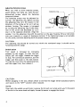
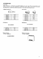
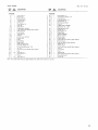
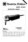
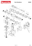
Screwdriver
MODEL 6805BV
Variable speed I Reversing
INSTRUCTION MANUAL
DOUBLE
INSULATION
SPEC IFI CATI0NS
Self drilling screw
Machine screw
Wood screw
* Manufacturer reserves the right t o change specifications without notice.
* Note: Specifications may differ from country to country.
WARNING: For your personal safety, READ and UNDERSTAND before using
SAVE THESE INSTRUCTIONS FOR FUTURE REFERENCE.
IMPORTANT
SAFETY INSTRUCTIONS
(For All Tools)
WARNING: WHEN USING ELECTRIC TOOLS, BASIC SAFETY
PRECAUTIONS SHOULD ALWAYS BE FOLLOWED TO REDUCE
THE RISK OF FIRE, ELECTRIC SHOCK, AND PERSONAL
INJURY, INCLUDING THE FOLLOWING:
READ ALL INSTRUCTIONS.
1. KEEP WORK AREA CLEAN. Cluttered areas and benches invite injuries.
2. CONSIDER WORK AREA ENVIRONMENT. Don't use power tools in damp
or wet locations. Keep work area well lit. Don't expose power tools t o rain.
Don't use tool in presence of flammable liquids or gases.
3. KEEP CHILDREN AWAY. All visitors should be kept away from work area.
Don't let visitors contact tool or extension cord.
4.STORE IDLE TOOLS. When not in use, tools should be stored in dry, and high
or locked-up place - out of reach of children.
5. DON'T FORCE TOOL. It will do the job better and safer at the rate for which
it was intended.
6. USE RIGHT TOOL. Don't force small tool or attachment t o do the job of a
heavy-duty tool. Don't use tool for purpose not intended.
7 . DRESS PROPERLY. Don't wear loose clothing or jewelry. They can be caught
in moving parts. Rubber gloves and non-skid footwear are recommended
when working outdoors. Wear protective hair covering t o contain long hair.
8 . USE SAFETY GLASSES. Also use face or dust mask if cutting operation is
dusty.
9. DON'T ABUSE CORD. Never carry tool by cord or yank it t o disconnect from
receptacle. Keep cord from heat, oil, and sharp edges.
10. SECURE WORK. Use clamps or a vise t o hold work. It's safer than using
your hand and it frees both hands t o operate tool.
11. DON'T OVERREACH. Keep proper footing and balance at all times.
12. MAINTAIN TOOLS WITH CARE. Keep tools sharp and clean for better and
safer performance. Follow instructions for lubricating and changing accessories. Inspect tool cords periodically and if damaged, have repaired by authorized service facility. Inspect extension cords periodically and replace if
damaged. Keep handles dry, clean, and free from oil and grease.
13. DISCONNECT TOOLS. When not in use, before servicing, and when changing accessories, such as blades, bits, cutters.
2
14. REMOVE ADJUSTING KEYS AND WRENCHES. Form habit of checking t o
see that keys and adjusting wrenches are removed from tool before turning
it on.
15. AVOID UNINTENTIONAL STARTING. Don’t carry tool with finger on switch.
Be sure switch is OFF when plugging in.
16. OUTDOOR USE EXTENSION CORDS. When tool is used outdoors, use only
extension cords intended for use outdoors and so marked.
17. STAY ALERT. Watch what you are doing, use common sense. Don’t operate
tool when you are tired.
18. CHECK DAMAGED PARTS. Before further use of the tool, a guard or other
part that is damaged should be carefully checked t o determine that it will
operate properly and perform its intended function. Check for alignment of
moving parts, binding of moving parts, breakage of parts, mounting, and
any other conditions that may affect its operation. A guard or other part
that is damaged should be properly repaired or replaced by an authorized
service center unless otherwise indicated elsewhere in this instruction
manual. Have defective switches replaced by authorized service center. Don‘t
use tool if switch does not turn it on and off.
19. GUARD AGAINST ELECTRIC SHOCK. Prevent body contact with grounded
surfaces. For example; pipes, radiators, ranges, refrigerator enclosures.
20. REPLACEMENT PARTS. When servicing, use only identical replacement parts.
21. POLARIZED PLUGS. To reduce the risk of electric shock, this equipment has
a polarized plug (one blade is wider than the other). This plug will fit in a
polarized outlet only one way. If the plug does not fit fully in the outlet,
reverse the plug. If it still does not fit, contact a qualified electrician to install
the proper outlet. Do not change the plug in any way.
VOLTAGE WARNING: Before connecting the tool t o a power source (receptacle,
outlet, etc.) be sure the voltage supplied is the same as that specified on the
nameplate of the tool. A power source with voltage greater than that specified
for the tool can result in SERIOUS INJURY t o the user - as well as damage t o
the tool. If in doubt, DO NOT PLUG IN THE TOOL. Using a power source w i t h
voltage less than the nameplate rating is harmful t o the motor.
3
ADDITIONAL SAFETY RULES
1.
Always be sure you have a firm footing.
Be sure no one is below when using the tool in high locations.
2.
Hold the tool firmly.
3. Keep hands away from rotating parts.
4.
When driving into walls, floors or wherever "live" electrical wires may be
encountered, DO NOT TOUCH ANY METAL PARTS OF THE TOOL!
Hold the tool only by the insulated grasping surfaces t o prevent electric shock
if you drive into a "live" wire.
5.
Do not touch the bit or the workpiece immediately after operation: they may
be extremely hot and could burn your skin.
SAVE THESE INSTRUCTIONS.
4
Removing or installing bit
CAUTION :
Always be sure that the tool is switched off and unplugged before removing or installing
the bit.
To remove the bit, first pull the front cap
off and then pull the bit firmly. To install
the bit, insert it into the tool as far as it
will go and then replace the front cap.
Depth adjustment
When you wish to drive self drilling screws,
etc., adjust the depth as follows. Turn the
locator to adjust the depth.
I
Initially, adjust the locator to create a distance of approximately 1 mm (3/64”)
from
the tip of the front cap (which works in
conjunction with the locator) to the base
of the screw head. One full turn of the
locator equals 1 mm (3/64“) change in
depth. After adjusting the locator, turn
the adjusting ring so that the 6” mark i s
aligned with the pointer on the gear housing. Drive a trial screw into your material
or a piece of duplicate material. If the
depth i s not suitable for the screw, continue adjusting until the proper depth setting i s obtained.
Adjusting nig
r-
\\
1 mm (3/64”)
1 mm (3/64”)
5
Adjusting fastening torque
When you wish to drive machine screws, I
wood screws, hex bolts etc. with the predetermined torque, adjust the fastening
torque as follows.
The fastening torque may be adjusted by
turning the adjusting ring. Before turning
the adjusting ring, turn the locator in the
direction of the arrow as far as it will go
without forcing. The torque is increased
by turning the adjusting ring in the direction of the arrow and decreased by turning it in the opposite direction. Align the
number 1 on the adjusting ring with the pointer on the gear housing. Drive a trial screw
into your material or a piece of duplicate material. If the fastening torque i s not suitable
for the screw, continue adjusting until the proper torque is obtained.
CAUTION :
The adjusting ring should be turned only within the numbered range. It should not be
forced beyond this range.
Switch action
Tool speed is increased by increasing
pressure on the trigger. To start the tool,
simply pull the trigger. Release the trigger
to stop. For continuous operation, pull the
trigger and then push in the lock button.
To stop the tool from the locked position,
pull the trigger fully, then release it.
I
Trigger switch
Lock button
I
CAUTION :
Before plugging in the tool, always check to see that the trigger switch actuates properly
and returns to the "OFF" position when released.
NOTE :
Even with the switch on and motor running, the bit will not rotate until you fit the point
of the bit in the screw head and apply forward pressure to engage the clutch.
6
Reversing switch action
This tool has a reversing switch to change
the direction of rotation. Move the reversing switch lever to the
position for
clockwise rotation or the
position for
counterclockwise.
&?
Reversing switch lever
1
CAUTION :
Always check the direction of rotation before operation.
*Use the reversing switch only when the tool comes to a complete stop. Changing the
direction of rotation before the tool stops may ruin the tool.
Operation
Fit the screw on the point of the bit and
place the point of the screw on the surface
of the workpiece to be fastened. Apply
pressure to the tool and start it. Withdraw
the tool as soon as the clutch cuts in.
Then release the trigger.
CAUTION :
Use the proper bit for the head of the screw that you wish to use.
When fitting the screw onto the point of the bit, be careful not to push in on the screw.
If the screw i s pushed in, the clutch will engage and the screw will rotate suddenly. This
could damage a workpiece or cause an injury.
0
Do not continue unnecessary clutching operation.
7
NOTE :
Make sure that the driver bit is inserted straight in the screw head, or the screw and/or
bit may be damaged.
0
When driving wood Screws, predrill pilot
holes to make driving easier and to prevent splitting of the workpiece. See the
chart.
of wood screw
of pilot hole
1/8"
1 1/64"
3/16"
13/64"
iia"
9/64"
5/32"
7/32"
15/64"
114"
I
1 1/64"
11 164''
MAINTENANCE
CAUTION :
Always be sure that the tool is switched off and unplugged before attempting to perform
inspection or maintenance.
To maintain product SAFETY and RELIABILITY, repairs, carbon brush inspection and
replacement, any other maintenance or adjustment should be performed by Makita
Authorized or Factory Service Centers, always using Makita replacement parts.
8
ACCESSORIES
CAUTION :
These accessories or attachments are recommended for use with your Makita tool specified in this
manual. The use of any other accessories or attachments might present a risk of injury to persons.
The accessories or attachments should be used only in the proper and intended manner,
0
Magnetic socket bit
Front cap
I
Part No.
784803-7
I
784805-3
Size
Part No.
114"
3221 24-5
I
Size
114''
,
7/16"
322120-3
0
Phillips bit
Slotted bit
Size
Part No.
~~
.
I
784215-0A
Square drill bit
Part No. 784606-0A
I
#3
Part No.
784010-OA
784011-0A
I
1
I
Size
#5F
#7F
Steel carrying case
Part No. 181853-7
9
May-28-'93
US
SCREWDRIVER
Model 6805BV
Note: The switch, noise suppressor and other part configurations
may differ from country to country.
10
MODEL 6805BV
May-28-'93
DESCRIPTION
1
2
1
1
Front Cap 12
0 Ring 2 0
3
1
AdiuSf Sleeve
4
5
1
1
6
1
1
1
1
Ring Spring 22
Clutch Cover
0 Ring 34
Flat Washer 36
Ring 36
Steel Ball 4
Compression Spring 4
Pan Head Screw M5x50 [With Washerl
Gear Housing
Leaf spring
Steel Ball 3 5
Spindle
Compression Spring 6
Clutch Cam
Hook
Leaf Spring
Name Plate
7
8
9
10
11
12
13
14
15
16
17
18
19
20
22
23
24
25
26
27
28
29
30
31
1
2
1
1
I
1
1
1
1
1
1
1
1
1
1
1
1
26
1
1
16
Gear Housing Cover
Urethane Washer 10
Thrust Needle Bearing 1023
Pl" 3 5
Pan Head Screw M5x40 (With Washer1
Gear
Steel Ball 3 2
Flat Washer 14
Sleeve
Steel Ball 3 2
US
DESCRIPTION
32
33
34
35
36
37
38
39
1
1
3
1
1
1
1
40
41
42
43
44
45
46
47
48
49
1
1
1
1
50
51
52
53
54
57
58
59
60
61
62
-
1
1
1
2
2
2
1
2
1
1
3
1
1
1
1
2
1
1
-
Flat Washer 14
Compression Spring 13 6
Steel Ball 5 6
Urethane Washer 14
Flat Washer 14
Ball Rearing 608LB
Fan 52
ARMATURE ASSEMBLY
lWlth Item 37
401
Ball Bearing 627LB
Rubber Pin 4
Flat Washer 14
Baffle Plate
FIELD ASSEMBLY
Motor Housing
Brush Holder
Carbon Brush
Pan Head Screw M4x14 [With Washer1
Switch Cover
Hex Bolt M4x55 IWith Washerl
Rubber Pin 4
Handle Cover
Pan Head Screw M4x28 [With Washerl
Switch
Cord Guard
Cord
Strain Relief
Pan Head Screw M4x18 (With Washerl
Reversing Switch
0 Rinq 2 4
Note The switch and other part specifications may differ from country to country
11
P
MAKlTA LIMITEDONE YEAR WARRANTY
Warranty Policy
Every Makita tool is thoroughly inspected and tested before leaving the factory. It is warranted t o
be free of defects from workmanship and materials for the period of ONE YEAR from the date of
original purchase. Should any trouble develop during this one-year period, return the COMPLETE
tool, freight prepaid, to one of Makita’s Factory or Authorized Service Centers. If inspection shows
the trouble is caused by defective workmanship or material, Makita will repair (or at our option,
replace) without charge.
This Warranty does not apply where:
0 repairs have been made or attempted by others:
0 repairs are required because of normal wear and tear:
0 The tool has been abused, misused or improperly maintained ;
0 alterations have been made to the tool.
IN NO EVENT SHALL MAKITA BE LIABLE FOR ANY INDIRECT, INCIDENTAL OR CONSEQUENTIAL DAMAGES FROM THE SALE OR USE OF THE PRODUCT. THIS DISCLAIMER
APPLIES BOTH DURING AND AFTER THE TERM OF THIS WARRANTY.
MAKITA DISCLAIMS LIABILITY FOR ANY IMPLIED WARRANTIES, INCLUDING IMPLIED
WARRANTIES OF “MERCHANTABILITY” AND “FITNESS FOR A SPECIFIC PURPOSE,”
AFTER THE ONE-YEAR TERM OF THIS WARRANTY.
This Warranty gives you specific legal rights, and you may also have other rights which vary from
state to state. Some states do not allow the exclusion or limitation of incidental or consequential
damages, so the above limitation or exclusion may not apply to you. Some states do not allow
limitation on how long an impl~edwarranty lasts, so the above limitation may not apply to you.
Makita Corporation
3-11-8, Sumiyoshi-cho,
Anjo, Aichi 446 Japan
8835870067
PRINTED IN JAPAN
1993 - 7 - N