1
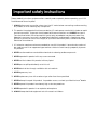
Operating Manual
Mark Levinson®
Nº29
Dual Monaural
Power Amplifier
Madrigal Audio Laboratories, Inc.
17
WARNING: TO REDUCE THE RISK OF FIRE OR ELECTRIC SHOCK,
DO NOT EXPOSE THIS APPLIANCE TO RAIN OR MOISTURE.
CAUTION
RISK OF ELECTRIC SHOCK
DO NOT OPEN
CAUTION: TO REDUCE THE RISK OF ELECTRICAL SHOCK,
DO NOT REMOVE COVER. NO USER-SERVICEABLE PARTS
INSIDE. REFER SERVICING TO QUALIFIED PERSONNEL.
The lightning flash with arrowhead symbol, within an equilateral triangle, is intended to alert the
user to the presence of uninsulated “dangerous voltage” within the product’s enclosure that may
be of sufficient magnitude to constitute a risk of electric shock to persons.
The exclamation point within an equilateral triangle is intended to alert the user to the presence of
important operating and maintenance (servicing) instructions in the literature accompanying the
appliance.
18
Important safety instructions
Please read all instructions and precautions carefully and completely before operating your Nº 29
Dual Monaural Power Amplifier.
1. ALWAYS disconnect your entire system from the AC mains before connecting or disconnecting
any cables, or when cleaning any component.
2. This product is equipped with a three-conductor AC mains power cord which includes an earth
ground connection. To prevent shock hazard, all three connections must ALWAYS be used. If
your electrical outlets will not accept this type of plug, an adapter may be purchased. If an
adapter is necessary, be sure it is an approved type and is used properly, supplying an earth
ground. If you are not sure of the integrity of your home electrical system, contact a licensed
electrician for assistance.
3. AC extension cords are not recommended for use with this product. If an extension cord must
be used, be sure it is an approved type and has sufficient current-carrying capacity to power
this product.
4. NEVER use flammable or combustible chemicals for cleaning audio components.
5. NEVER operate this product with any covers removed.
6. NEVER wet the inside of this product with any liquid.
7. NEVER pour or spill liquids directly onto this unit.
8. NEVER block air flow through ventilation slots or heatsinks.
9. NEVER bypass any fuse.
10. NEVER replace any fuse with a value or type other than those specified.
11. NEVER attempt to repair this product. If a problem occurs, contact your Mark Levinson® dealer.
12. NEVER expose this product to extremely high or low temperatures.
13. NEVER operate this product in an explosive atmosphere.
14. ALWAYS keep electrical equipment out of the reach of children.
19
Thank you for choosing the Mark Levinson® Nº29 Dual Monaural Power Amplifier.
A great deal of effort went into the design and construction of this precision device. Used properly, it
will give you many years of enjoyment.
20
Table of contents
Unpacking and placement ....................................................................... 1
Unpacking ................................................................................................. 1
Placement ................................................................................................. 1
Ventilation ................................................................................................. 1
Custom installations .................................................................................. 1
Voltage selection ........................................................................................ 2
Figure 1: Rear-panel label .................................................................... 2
Signal connections ..................................................................................... 3
Connectors ............................................................................................... 3
Cables ........................................................................................................ 3
Connection methods and operating modes ....................................... 3
Single-ended normal (non-inverting) operation ................................... 3
Figure 2: Connections for single-ended normal (non-inverting)
operation ......................................................................................... 3
Figure 3: Female input connector ....................................................... 4
Single-ended inverting operation .......................................................... 4
Figure 4: Connections for single-ended inverting operation ........... 4
Balanced normal (non-inverting) operation ......................................... 5
Figure 5: Connections for balanced normal (non-inverting)
operation ......................................................................................... 5
Speaker connections ................................................................................. 6
Speaker cables ......................................................................................... 6
Lug connection ........................................................................................ 6
Figure 6: Spade and hook lugs ............................................................ 6
Pigtail connection .................................................................................... 6
Figure 7A: Pigtail connection ............................................................... 6
Figure 7B: Pigtail connection ............................................................... 7
Figure 7C: Pigtail connection .............................................................. 7
Connecting the speakers ........................................................................ 7
Power connection ....................................................................................... 8
Connecting the AC power cord ............................................................ 8
Figure 8: AC power cord polarity ........................................................ 8
Performance tips ...................................................................................... 8
Protection circuitry ................................................................................... 8
Bridged operation ....................................................................................... 9
Balanced bridged operation .................................................................. 9
Figure 9: Connections for balanced bridged operation ................. 9
Figure 10: Balanced bridging cable ................................................. 10
Single-ended bridged operation ......................................................... 10
Figure 11: Connections for single-ended bridged operation ........ 10
Figure 12: Single-ended bridging cable ........................................... 11
Care and maintenance ........................................................................... 12
Cleaning .................................................................................................. 12
Fuses ......................................................................................................... 12
Specifications ............................................................................................ 13
Dimensions ................................................................................................. 14
Figure 13A: Dimensions, Nº29, top view ............................................ 14
Figure 13B: Dimensions, Nº29, side view ............................................ 14
21
Unpacking and placement
Unpacking
PRECAUTION
Unpack your Nº29 amplifier and keep all packing materials for future
transport.
To avoid damaging the connectors on input cables attached to
the rear panel, NEVER rest the Nº29 on the rear panel, and
NEVER tip it back in a way that would put stress on these
connectors.
Carefully inspect your Nº29 for damage and flaws. If you find any, see
your Mark Levinson dealer immediately.
Placement
To keep speaker cables as short as possible, place the Nº29 as close to
the loudspeakers as practical.
Place the Nº29 at least three feet from the turntable and preamplifier.
Otherwise, the Nº29 may induce hum into these sensitive components.
Ventilation
The Nº29 may be placed in a cabinet or on a shelf, but adequate
ventilation must be provided to prevent overheating. The clearance
provided by the unit's feet must be maintained to ensure unrestricted
air flow across the bottom of the chassis. (Placing the Nº29 on
carpeting, for example, may prevent adequate air circulation.)
Clearance above the unit must also be maintained to allow air
circulation and to prevent heat buildup.
The Nº29 incorporates thermal sensors located near each group of
output devices. If the internal heatsink temperature becomes
excessive, these sensors will shut off the amplifier before damage
results. After a brief cooling period, the amplifier can be reactivated
via the front-panel switch. If this occurs regularly during normal use, it's
an indication that the ventilation provided for the amplifier is
inadequate. If there's adequate ventilation and the problem
continues, see your Mark Levinson dealer immediately.
Custom installations
For those involved in custom installations and cabinetry, this
information may be useful:
■ All temperature measurements are made at the bottom of the
internal heatsink, 2 inches above the chassis floor.
■ Normal heatsink temperature at idle after warmup with
unrestricted airflow at 22°C (72°F) ambient temperature: 35°C
(95°F).
■ Maximum permissible heatsink temperature before thermal
protection is activated: 80°C (176°F).
Drawings are included in this manual to facilitate special installations
and custom cabinetry (see "Dimensions").
PRECAUTION
For your protection, review "Important safety instructions" before
you install your Nº29.
1
Voltage selection
The Nº29 is factory-set (internally) for 100V, 120V, 200V, 220V, or 240V
AC mains operation. Check that the label on the rear panel of the
amplifier indicates the correct AC operating voltage for your location.
Figure 1: Rear-panel label
Voltage
indication
®
Nº 29
DUAL MONAURAL AMPLIFIER
OPERATING VOLTAGE:
●
●
●
●
●
90 – 110 VAC~
105 – 125 VAC~
180 – 220 VAC~
210 – 240 VAC~
230 – 250 VAC~
~47 – 400 HZ
OUTPUT
+
–
INPUT
INPUT
RIGHT CHANNEL
WARNING:
–
BALANCED
INPUT
+
BALANCED
INPUT
INPUT
LEFT CHANNEL
HAZARDOUS VOLTAGES AVAILABLE INSIDE: DISCONNECT AC~ MAINS CABLE BEFORE REMOVING ANY
COVERS. HIGH ENERGY AVAILABLE AT LOAD TERMINALS: REFER TO OWNER'S MANUAL FOR PROPER
TERMINATION INSTRUCTIONS. DISCONNECT AMPLIFIER FROM AC~ MAINS BEFORE REPLACING FUSES.
MAINS FUSES: PLEASE CONSULT OWNER'S MANUAL.
DESIGNED AND MANUFACTURED IN U.S.A. BY
MAD R I GAL AU D I O LAB O RAT O R I E S , I N C .
SERIAL NO.
If the voltage indicated is incorrect, see your Mark Levinson dealer.
If you wish to change the AC operating voltage of your Nº29, see your
Mark Levinson dealer.
A Nº29 may be powered by a 15-ampere AC mains line. If other
devices are also powered from the same AC feed, their additional
power consumption must be considered.
The Nº29's fuses are located on the rear panel. Replace the fuses with
the same type only.
PRECAUTION
2
ALWAYS remove the AC cord before removing the fuses.
Signal connections
Connectors
The Nº29 incorporates RCA-type and XLR-type connectors for audio
signal input.
The Madrigal-designed RCA-type connectors used for single-ended
audio interconnection are a great improvement over ordinary RCAtype connectors. The gold-plated XLR-type connectors employed are
of European design, and are made to professional application
standards.
Cables
Connection methods and
operating modes
For connecting the Nº29 to a preamplifier, we recommend Madrigal
Audio Laboratories HPC Interconnect Cable. HPC is available in
various lengths, pre-terminated with RCA, XLR, and Camac
connectors. For more information, see your Mark Levinson dealer.
The Nº29 can be operated in either single-ended or balanced mode.
In each of these modes, the Nº29 can be operated either normally
(non-inverting) or inverting.
This manual describes the connections for single-ended normal (noninverting), single-ended inverting, and balanced normal (noninverting) operation. If you have questions about these or other
methods of signal connection, see your Mark Levinson dealer.
PRECAUTION
Single-ended normal
(non-inverting) operation
Before making any signal or speaker connections, make sure
that the Nº29 is disconnected from your preamplifier and from
the AC mains.
Typical audio systems require that the amplifier be of the non-inverting
type. This means that the output signal of the amplifier will be in phase
with the input signal.
For this type of operation, connect the main outputs of the
preamplifier to the appropriate (left and right channel) RCA-type
inputs (non-inverting) on the rear panel of the Nº29. Be sure that the
shorting strap is inserted into the XLR-type connectors between Pins 1
and 3.
Figure 2: Connections for
single-ended normal
(non-inverting) operation
Nº29
+
–
–
+
–
–
+
+
PUSH
PUSH
Shorting strap
Right
Loudspeaker
Right
channel
Left
channel
Left
Loudspeaker
From preamplifier main output
3
Single-ended inverting
operation
Inverting operation should be used if a phase reversal is required. In
this mode of operation, the output signal of the amplifier will be 180°
out of phase with the input signal. This may be required if one
component in the system inverts the signal and absolute phase at the
loudspeaker is desired.
For inverting operation, the main output cables of the preamplifier
must be connected to the XLR-type inputs on the rear panel of the
Nº29. The pin assignments of these connectors are:
Figure 3: Female input
connector
PUSH
2 1
3
Pin 1: Signal ground
Pin 2: Signal + (non-inverting)
Pin 3: Signal – (inverting)
Connector ground lug: chassis ground
Connect the XLR-type male line-mount connector to the preamplifier
main output cable so that signal "hot" (+) connects to Pin 3 and signal
ground connects to Pin 1. Be sure to also connect Pin 2 to Pin 1 inside
the XLR-type male line-mount connector with a piece of copper buss
wire (or similar material) at the amplifier end of the cable.
Note: If you prefer not to connect Pin 2 to Pin 1 inside the XLRtype male line-mount connector, pre-shorted RCA-type input
connectors are available from your Mark Levinson dealer. Insert
one of these connectors into each of the RCA-type inputs (noninverting) on the rear panel of the Nº29.
After completing the cables, connect the main outputs of the
preamplifier to the left- and right-channel XLR-type inputs on the rear
panel of the Nº29. Be sure to remove the shorting strap between Pins 1
and 3 before inserting the output cable connectors.
Figure 4: Connections for
single-ended inverting
operation
Nº29
+
–
–
+
–
–
PUSH
Right
Loudspeaker
Right
channel
From preamplifier main output
4
+
+
PUSH
Left
channel
Left
Loudspeaker
Balanced normal
(non-inverting) operation
If your preamplifier is equipped with a balanced main output, it's best
to wire the Nº29 for balanced operation, particularly if long cable
lengths are required between the preamplifier and the Nº29. (See
Figure 3 for the pin assignments of the Nº29's XLR-type inputs.)
Connect the XLR-type male line-mount connector to the preamplifier,
carefully observing pin assignments. (Refer to your preamplifier's
operating manual to verify that the pin assignments of its output
correspond to the diagram above. If they don't, wire the connector so
that the appropriate output pin connects to the equivalent input pin.)
When complete, connect the main outputs of the preamplifier to the
left- and right-channel XLR-type inputs on the rear panel of the Nº29.
Be sure to remove the shorting strap between Pins 1 and 3 before
inserting the output cable connectors.
Note: For proper balanced operation, no connector (preshorted or otherwise) should be inserted into the RCA-type
inputs on the rear panel of the Nº29.
Figure 5: Connections for
balanced normal
(non-inverting) operation
Nº29
+
–
–
+
–
–
PUSH
Right
Loudspeaker
+
+
PUSH
Right
channel
Left
channel
Left
Loudspeaker
From preamplifier
balanced
main output
5
Speaker connections
PRECAUTION
NEVER connect the Nº29's output terminals to any device other than a
loudspeaker.
PRECAUTION
NEVER short-circuit the amplifier output terminals.
PRECAUTION
NEVER connect the left-channel output terminals to the right-channel
output terminals.
Speaker cables
The Nº29 is equipped with gold-plated, high-current, five-way binding
posts for output termination to a loudspeaker system. To take full
advantage of the sonic quality of the Nº29, we recommend using
high-quality speaker cable. See your Mark Levinson dealer for
recommendations.
Lug connection
There are two recommended methods for connecting speaker cables
to the Nº29. A high-quality spade- or hook-type lug, soldered to the
cable, is best.
Figure 6: Spade and
hook lugs
Spade lug
Hook lug
We confidently recommend Madrigal binding-post lugs, made of
oxygen-free copper with gold-over-silver plating. These lugs are
available for round cable; see your Mark Levinson dealer for more
information.
Many lug connectors are designed to be crimped onto the cable.
However, soldering will ensure a better electrical connection.
Note: If you have no experience in soldering, see your Mark
Levinson dealer for assistance.
Pigtail connection
The "pigtail" is another method of connection which uses a short piece
of 14-gauge wire soldered to the speaker cable. The other end of this
14-gauge wire is inserted through the hole in the five-way binding
posts on the rear panel of the Nº29.
1. Begin with 3" of 14-gauge copper wire.
2. Strip 5/8" of insulation from one end, and strip 1/2" of insulation
from the opposite end:
5/8"
(15.8mm)
1/2"
(12.7mm)
Figure 7A: Pigtail
connection
14-gauge wire
3"
(76.2mm)
6
3. Strip 1/2" of insulation from the speaker cable.
4. Gently slide the (5/8") bare end of the 14-gauge wire into the
center of the bare speaker cable (be careful not to spread the
individual wires of the speaker cable).
1/2"
(12.7mm)
Tin
Figure 7B: Pigtail
connection
Speaker cable
Solder
5. Solder this connection. A high-wattage soldering gun may be
necessary to provide adequate heat.
6. Lightly "tin" the remaining (1/2") bare end of the 14-gauge wire.
7. Gently slide a 1" length of shrink tubing over the connection and
heat to shrink. (Color-coded shrink tubing is available for polarity
identification.)
Figure 7C: Pigtail
connection
5/8" (15.8mm) shrink tubing
8. Follow this procedure for the remaining speaker connections.
Depending upon the type of speaker terminal, this procedure may
also be used for the speaker end of the cable.
Connecting the speakers
When the speaker cables are complete, connect the left-channel +
(positive or red) output post of the Nº29 to the + (positive or red) input
terminal of the appropriate loudspeaker.
Connect the left-channel – (negative or black) output post of the Nº29
to the – (negative or black) input terminal of the appropriate
loudspeaker.
Repeat this procedure for the right channel.
Note: The Nº29 provides two sets of output posts to
accomodate the increasing number of loudspeakers that call
for bi-wiring. For specific instructions on bi-wiring, refer to your
loudspeaker owner's manual or see your Mark Levinson dealer.
For the best sonic peformance, we recommend against using
the two sets of output posts to connect two sets of full-range
loudspeakers. Doing so, however, won't damage the Nº29, as
long as the total load impedance is at least 2Ω.
7
Power connection
After making your loudspeaker connections, apply power to your
preamplifier and allow it to stabilize. (Mark Levinson preamplifiers, for
example, require about one minute to stabilize.)
Connecting the
AC power cord
Connect the AC power cord (included in the accessory pack) to the
AC connector on the rear panel of the Nº29, then to the AC mains
outlet.
To Nº29
To AC mains
Figure 8: AC power cord
polarity
1
2
3
2
1
1 = Line (hot)
2 = Neutral
3 = Earth ground
3
Turn on the Nº29 by setting the power switch on the front panel to the
"|" (on) position.
Note: You may hear a transient "click" or "pop" through your
speakers a few seconds after you operate the Nº29's power
switch. This noise is normal and won't damage your speakers.
Performance tips
The Nº29 won't achieve its sonic potential right away — its sonic
performance is close to the optimum after about 100 hours of use. For
the best performance, you may leave your Nº29 powered at all times,
except when you won't be using it for a long period (see "Important
Safety Instructions").
The Nº29 is designed to be "power-cycled" (that is, turned on and off)
without affecting its longevity. After the amplifier is turned on after
being left unpowered, allow for about one hour of warmup before
expecting optimal sonic performance.
Protection circuitry
Under certain conditions (an electrical malfunction or inadequate
ventilation), the Nº29's protection circuitry may activate, turning off the
amplifier before damage results. When this happens, the power switch
on the front panel will be set automatically to the "O" (off) position.
After a brief cooling period, you can reactivate the amplifier by
setting the power switch to the "|" (on) position.
If this occurs regularly during normal use, see your Mark Levinson
dealer immediately.
Note: While the protection circuitry is active, the power switch
won't stay in the "|" (on) position. If, after the amplifier has
cooled, the power switch still won't engage, the protection
circuitry still detects a malfunction; see your Mark Levinson
dealer immediately.
8
Bridged operation
When greater power output is desired, the Nº29 may be bridged for
monophonic operation into load impedances of at least 2Ω.
Note: Make sure the loudspeaker is rated to handle high power
levels. For example, a bridged Nº29 driving an 8Ω loudspeaker is
capable of delivering 200W RMS.
Balanced
bridged operation
For the best bridged performance, we recommend balanced
interconnection. If your preamplifier provides balanced output, follow
the steps below.
Nº29
Figure 9: Connections for
balanced bridged
operation
–
+
–
–
PUSH
+
+
PUSH
Loudspeaker
Balanced
bridging cable
From preamplifier
balanced main output
1. For balanced bridged operation, you'll need a special threeended cable. You may fabricate such a cable according to
Figure 10; it's also available through your Mark Levinson dealer as
part of a balanced bridging kit.
Note: If fabricating the cable, be sure to use high-quality
audio interconnect cable (such as Madrigal HPC).
Connect the bridging cable's female XLR-type connector to the
appropriate channel of your preamplifier's balanced main output.
9
XLR female
line-mount
(rear view)
1
2
3
Signal ground
(shield)
Twisted pair
Figure 10: Balanced
bridging cable
2
Left-channel
XLR male
line-mount
(rear view)
1
Signal ground (shield)
3
2
Twisted pair
1
Right-channel
XLR male
line-mount
(rear view)
3
2. Connect the bridging cable's male XLR-type connectors to the
Nº29's left- and right-channel XLR-type input connectors, taking
care to insert the correct cable end into its designated channel.
3. Connect the left-channel + (positive or red) output post of the
Nº29 to the + (positive or red) input terminal of the appropriate
loudspeaker. Connect the right-channel + (positive or red) output
post of the Nº29 to the – (negative or black) input terminal of the
same loudspeaker.
4. Repeat this procedure for the other Nº29 to be bridged.
If your preamplifier provides only single-ended output, follow the steps
below.
Nº29
Figure 11: Connections for
single-ended bridged
operation
–
+
–
–
+
+
Bridging
cable
PUSH
Left
channel
PUSH
Loudspeaker
From preamplifier
main output
1. Connect the appropriate channel of your preamplifier's singleended main output to the left-channel RCA-type input on the
rear panel of the Nº29.
10
2. Connect the bridging cable between the left- and right-channel
XLR-type input connectors, taking care to insert the correct cable
end into its designated channel. You may fabricate such a cable
according to Figure 12; it's also available through your Mark
Levinson dealer as part of a single-ended bridging kit.
Note: If fabricating the bridging cable, be sure to use highquality audio interconnect cable (such as Madrigal HPC).
22-guage
buss wire
Figure 12: Single-ended
bridging cable
Left-channel
XLR male
line-mount
(rear view)
2
1
Signal ground (shield)
3
2
1
3
Right-channel
XLR male
line-mount
(rear view)
Signal hot (center conductor)
22-guage
buss wire
3. Connect the left-channel + (positive or red) output post of the
Nº29 to the + (positive or red) input terminal of the appropriate
loudspeaker. Connect the right-channel + (positive or red) output
post of the Nº29 to the – (negative or black) input terminal of the
same loudspeaker.
4. Repeat this procedure for the other Nº29 to be bridged.
11
Care and maintenance
Cleaning
To remove dust from the cabinet of the Nº29, use a feather duster. To
remove dirt and fingerprints, use isopropyl alcohol applied to a soft
cloth.
Poor connections cause sonic degradation. We recommend,
therefore, that you clean all speaker connection with denatured
alcohol at least once a year. Consult your Mark Levinson dealer for
other ways to optimize connections.
Fuses
PRECAUTION
12
The Nº29's fuses are located on the rear panel. Replace the fuses with
the same type only.
ALWAYS remove the AC cord before removing the fuses.
Specifications
The correlation between published specifications and sonic quality is
unreliable. A list of numbers reveals virtually nothing. All technical
measurements must be subject to qualitative as well as quantitative
interpretation.
Measurements of the Nº29 yield excellent results by any standards.
However, only those specifications that apply to the actual operation
of the amplifier are included here.
■ Rated power: 50W minimum continuous sine wave power into 8Ω,
with both channels driven from 20Hz to 20KHz with no more than
0.1% THD (FTC). 100W minimum continuous sine wave power into 4Ω
with both channels driven from 20Hz to 20KHz with no more than
0.2% THD (FTC).
■ Peak output voltage: 30 volts @ rated line voltage @ 8Ω
■ Frequency response: (-3dB) 4Hz, 122KHz
■ Input impedance: 50KΩ shunted by 1.5nF
■ Voltage gain: 26dB
■ Power consumption: Typically 100W @ idle, 200W @ rated power, 8Ω
■ Overall dimensions: See "Dimensions"
■ Shipping weight: 39.25 lbs. (17.8kg)
■ Connector complement: Two RCA-type connectors
Two XLR-type connectors
Eight five-way binding posts
One IEC mains connector
For more information, see your Mark Levinson dealer, or contact:
Madrigal Audio Laboratories, Inc.
2081 South Main Street (Route 17), P.O. Box 781
Middletown, Connecticut 06457 USA
Telephone (203) 346-0896
(FAX (203) 346-1540
If purchased in North America, this Mark Levinson product’s warranty is owner-transferable.
Warranty conditions are valid only in the country where the product was originally purchased.
For warranty information and conditions on products purchased outside of North America,
contact your local dealer or regional distributor.
13
Dimensions
1/8"
(3.2)
Figure 13A: Dimensions,
Nº29, top view
1-3/4"
(44.5)
4-29/64"
(113.1)
17-1/2"
(444.5)
1-7/16"
TYP.
(36.5)
17-1/4"
(438.2)
1" TYP.
(25.4)
1-9/16"
(39.7)
1-3/32"
(27.5)
2-53/64"
(71.8)
4-1/8"
(104.8)
3/8"
(9.5)
14-3/16"
(360.4)
29/32"
(23.0)
21/32"
(16.7)
Figure 13B: Dimensions,
Nº29, side view
1-7/16"
(36.5)
5-7/8" 5-1/4"
(174.8) (133.4)
13/16" 7/64"
(20.7) (2.8)
14
1-5/8"
(41.3)
5/8"
(15.9)
3-45/64"
(94.1)
6-11/16"
169.9)
2-21/64"
(59.1)
MADRIGAL AUDIO LABORATORIES
2081 South Main Street, P.O. Box 781
Middletown, Connecticut 06457 USA
Telephone: (203) 346-0896
Fax: (203) 346-1540
®
is a registered trademark of Madrigal Audio Laboratories, Inc.
16
630042-1
©1993 Madrigal Audio Laboratories, Inc. All rights reserved.
Printed in U.S.A.