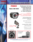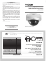
1
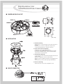
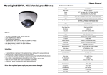
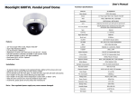
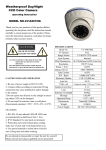
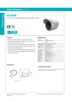
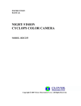
MACE Security Product Warranty
Mace will repair or replace, without charge, any merchandise proved
defective in material or workmanship for a period of one year after the date
of shipment.
Exceptions to this warranty are as noted below:
Mace will warrant all replacement parts and repairs for 90 days from the date
of Mace shipment. All goods requiring warranty repair shall be sent freight
prepaid to Mace, Fort Lauderdale. Repairs made necessary by reason of
misuse, alteration, normal wear, or accident are not covered under this
warranty.
High Resolution Color
Vandal Resistant Dome Camera
Model : CAM95
Mace assumes no risk and shall be subject to no liability for damages or loss
resulting from the specific use or application made of the Products. Mace’s
liability for any claim, whether based on breach of contract, negligence,
infringement of any rights of any party or product liability, relating to the
Products shall not exceed the price paid by the Dealer to Mace for such
Products. In no event will Mace be liable for any special, incidental or
consequential damages (including loss of use, loss of profit and claims of
third parties) however caused, whether by the negligence of Mace or
otherwise.
Instruction Guide
If a warranty repair is required, the Dealer must contact Mace at (877) 5856223 or (954) 585-6223 to obtain a Repair Authorization (RA) number, and
provide the following information:
1. Model and serial number
2. Date of shipment, P.O. number, Sales Order number, or Mace invoice
number
3. Details of the defect or problem
MACE Electronic Surveillance Products
3233 SW 2nd Ave. Fort Lauderdale, FL 33315 USA
toll-free(877)585-MACE
local(954)585-6223 fax(954)585-6225
www.mace.com
MACE Electronic Surveillance Products
High Resolution Color
Vandal Resistant Dome Camera
(Unit : mm)
142.78
46
103.5
83.5
■ DIMENSION
• 1/3” SONY Super HAD Color CCD
• Vari-Focal DC Auto Iris Lens (3.8mm ~ 9.5mm/F1.2)
• S/N Ratio more than 50dB
• Various Automatic Functions (DIP Switch built-in)
- BLC (Back Light Compensation) : ON/OFF
- ESC (Electronic Shutter Control) : AE/ALC
AE : 1/60sec. (NTSC), 1/50sec. (PAL) ~ 1/120,000sec. Variable
ALC : 1/60sec. (NTSC), 1/50sec. (PAL) Fixed
- AWB (Auto White Balance) : ATW/AWB
- MIRROR : ON/OFF
- ZOOM : ON (x2 Digital Zoom) / OFF
• 3 Axis built-in Vandal Resistant Outdoor Dome with Dual Power
■ FEATURES
ITEM
NTSC
PAL
1/3” Interline transfer type color CCD (SONY)
Image Sensor
768H X 494V (380K pixels) 752H X 582V (440K pixels)
Effective Pixels
525 Lines 2:1 Interlace
625 Lines 2:1 Interlace
Scanning System
Scanning Frequency 15.734KHz (H), 59.94Hz (V) 15.625KHz (H), 50Hz (V)
480 TV-Lines
Resolution
1/50~1/120,000sec.
1/60~1/120,000sec.
Shutter Speed
More than 50dB (AGC OFF)
S/N Ratio
Internal / Line Lock
Sync. System
ATW / AWB
White Balance
0.5 Lux / F1.5, 50 IRE
Min. IIIumination
VBS 1.0 Vp-p (75Ω Load)
Video Output
3.8mm ~ 9.5mm/F1.2 Vari-Focal DC Auto Iris Lens
Lens
AC24V / DC12V ±10%
Power Supply(*)
Max. 185mA
Power Consumption
–10°C ~ +50°C
Operating Temp.
90% RH max.
Operation Humidity
■ SPECIFICATIONS
High Resolution Color
Vandal Resistant Dome Camera
■ CAMERA MODULE LAYOUT
42
42
(Unit : mm)
■ INSTALLATION
1. Dome Base Mounting
- Open the dome cover by unscrewing 3 screws using special wrench
provided.
- Mount the base of camera to a sturdy surface using 4 screws
(1.5 inch) and 4 premade holes on the base of the dome.
2. Power Connect & Monitor Impedance
- AC24V Class 2 power supply.(AC24V/DC12V)
- To avoid fire or shock hazard, must use a UL listed power supply.
- Set the monitor impedance switch to 75Ω. Check the impedance
switch when the screen turns blurred.
3. Camera Module Adjustment
- Loosen screws for 3-axis camera bracket and adjust the direction and
angle of camera.
- Make sure to retighten the screws for camera bracket.
- Make necessary lens adjustment and DC Level using diagram shown
above.
- Set any function you wish to activate by using the DIP Switches.
4. Dome Cover Mounting
- Replace the dome cover to the base and tighten 3 screws.
■ CABLE CONNECTION
AC24V/DC12V
AC IN
DC IN
AC IN
DC IN