1
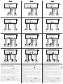
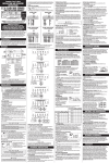
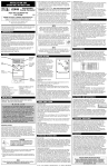
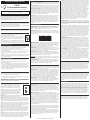
THERMOSTAT FRONT PANEL:
INSTALLATION AND OPERATING INSTRUCTIONS
LP0511D
5/2-Day Programmable Thermostat
52101
Lux Products Corporation - Mt. Laurel, New Jersey 08054 - http://www.luxproducts.com
WARNING: Use Energizer ® or DURACELL ® Alkaline Batteries Only.
Energizer ® is a registered trademark of Eveready Battery Company, Inc.
DURACELL ® is a registered trademark of The Gillette Company, Inc.
Thank you for your confidence in our product. To obtain the best results from your investment, please
read these instructions and acquaint yourself with your purchase. Follow the installation procedures
carefully, and save these instructions for future reference. This will save you time and minimize the
chance of damaging either the thermostat or the systems that it controls. NOTE: These instructions
may contain information beyond that required for your particular installation.
SYSTEM COMPATIBILITY:
This thermostat can be used with most single-stage 24 volt: gas, oil or electric heating and cooling
systems, single-stage heat pumps, or gas Millivolt heating systems.
It cannot be used with: 3-wire zone valves, 120/240 volt heating elements, or multi-stage heat pumps.
Ask your dealer for other LUX thermostats to control those systems.
TOOLS YOU MAY NEED:
Screwdrivers, wire stripper / cutter, and possibly a drill with assorted bits (new installations only).
REMOVAL OF OLD THERMOSTAT:
1. Turn OFF the electricity to all heating and cooling components. Do not turn the
electricity back on until all work is completed.
2. Remove the front portion of your old thermostat to expose the wiring connections.
3. Write down the letters printed near each wire terminal that is used, and also the
OFF
color of each wire that is connected to it. Self-adhesive wire labels are also
enclosed.
4. Carefully remove the wires one at a time, and bend them in a manner so that they
do not fall back inside the wall. Do not allow bare wire ends to touch each other.
5. Loosen the mounting screws for the old thermostat and carefully remove it from the wall.
THERMOSTAT MOUNTING LOCATION:
On replacement installations, mount the new thermostat in place of the old one unless the conditions
listed below suggest otherwise. On new installations, please follow these general guidelines:
1. Mount the thermostat on an inside wall, about 5 ft. (1.5m) above the floor.
2. Do not locate the thermostat where air circulation is poor such as in a corner, alcove, or behind a
door that is normally left open.
3. Do not locate the thermostat where unusual heating or cooling conditions may be present, such as:
direct sunlight, above a lamp, television, or radiator, or on a wall next to an exterior door or
window.
4. Do not locate in a damp environment, as this can lead to corrosion that may shorten thermostat life.
5. If painting or construction work is still ongoing, cover the thermostat completely or wait until this
work is complete before installation.
INSTALLATION OF NEW THERMOSTAT:
1. Strip wire insulation leaving only 3/8 in. (9.5mm) bare wire ends, and clean off any corrosion
present.
2. Fill the wall opening with non-combustible insulation to prevent drafts from affecting the
thermostat’s normal operation.
3. Route the wires through the opening in the new thermostat base plate, and hold the base against the
wall. Try to line up the screw holes from the prior thermostat, and install the mounting screws.
4. If the previous holes cannot be used, hold the thermostat base against the wall so that it appears
straight and level (position the base for best appearance) and mark for the new screw holes. Attach
the base to the wall using the screws provided (use the supplied plastic anchors if needed when
mounting to a soft material such as drywall).
WIRING TERMINAL CONNECTIONS:
1. When attaching the wires to the thermostat, please ensure that the bare wire ends are held ALL the
way into the terminal block while the screw is being tightened.
2. Securely tighten all of the electrical terminal screws, including any unused ones. Be careful not to
over tighten the screws, they only need to be snug.
** Complete heating and/or cooling system wiring can be found in the WIRE IDENTIFICATION AND
WIRING SCHEMATICS section of this instruction sheet. The schematics shown provide component
information for brand new installations or for unreferenced wires.
JP1 (CTRL): [UP = Manual Operation] The thermostat operates manually,
and only shows the room and set temperatures. In this mode, there are
no temperature programs, days of the week, or clock times. [DOWN =
Program Operation, default] The thermostat follows four temperature
programs: MORN, DAY, EVE, and NITE. Each period has a start time and
a set temperature.
AUTO / ON, FAN SWITCH: When this switch is in AUTO, the blower fan (if present in your system) will
automatically cycle on and off by itself when heating or cooling is running. When in the ON position,
the blower fan will run constantly with or without a demand for heating or cooling, even in OFF mode.
MULTI-FUNCTION, SET SLIDE SWITCH: Unless other settings are being adjusted, this switch should
always remain in the RUN position for the thermostat to control temperature. When this switch is in
the DAY/TIME position, the day and clock can be changed. When this switch is in the WEEKDAY or
WEEKEND positions, the heating and cooling temperature program periods can be adjusted. NOTE:
this switch is only used in “Program” mode. When the thermostat is used in “Manual” control mode,
all four of the switch positions will act like the RUN position.
RESET BUTTON: There is a small recessed push button located to the left of the DOWN button, which
can be pressed with a pen/pencil, paper clip, or similar object. A single press of this button causes
the LCD display screen to become fully populated, the heating/cooling load relay to cycle off, and
performs an internal system check of the thermostat components. If your thermostat is acting in an
erratic manner, pressing the Reset button may remedy this behavior. If your thermostat continues to
act erratically, a Full Software Reset may be needed. This and other additional features that can be
accessed using the same Reset button, which are explained in the ADVANCED FEATURES section of
this manual.
THERMOSTAT BASIC OPERATION:
SET DAY AND TIME: Place the Set Slide Switch into the DAY/TIME position. With the day flashing,
press UP or DOWN to set the day of the week. Press NEXT and the clock will start flashing. Use UP
or DOWN to set the time, making sure the AM/PM indication is correct. Holding UP or DOWN will
make the clock digits scroll rapidly. Return the Set Slide Switch to RUN.
HEATING AND COOLING: Basic operation of your heating or cooling system can be obtained with the
Set Slide Switch in the RUN position and choosing either HEAT or COOL on the System Mode Switch.
When the thermostat is first powered up, it will follow a default temperature routine that is preset from
the factory (shown below).
PERIOD
MORN
DAY
EVE
NITE
HEAT MODE
6:00 AM 70 °F (21 °C)
8:00 AM 62 °F (17 °C)
6:00 PM 70 °F (21 °C)
10:00 PM 62 °F (17 °C)
COOL MODE
6:00 AM 78 °F (26 °C)
8:00 AM 85 °F (29 °C)
6:00 PM 78 °F (26 °C)
10:00 PM 82 °F (28 °C)
TEMPERATURE OVERRIDE: While in Program mode, the set temperature can be temporarily changed by
pressing UP or DOWN. The set temperature will return to the programmed value stored in memory
when the start time of the next upcoming program period is reached (MORN, DAY, EVE, NITE). While a
Temporary Override is in effect, the word OVERRIDE will be shown in the display screen. An Override
may be cancelled moving the mode switch to OFF, then back to HEAT or COOL.
MINIMUM RUN TIME: The thermostat has an internal time delay of 5 minutes between load-on and
load-off activations to prevent heating or cooling system damage, which can occur from very frequent
cycling. If heating or cooling does not turn on right away with a change in set temperature, please
wait 5 minutes and the system should resume normal operation.
TEMPERATURE HOLD: A Temperature Hold is used for maintaining a fixed set temperature. Once a
Hold is initiated, the thermostat will maintain the set temperature indefinitely. A Hold may be used for
days, weeks, or even months at a time. To enter Hold mode: press HOLD one time and the word Hold
will appear in the display. To cancel a Hold, press HOLD one more time.
STATIC NOTICE: This thermostat is protected against normal minor static electric discharges, however
to minimize the risk of damaging the unit in extremely dry weather, please touch a grounded metal
object before touching your thermostat.
LCD DISPLAY BACKLIGHT: The display screen has backlighting that will assist viewing at nighttime, or
in locations with low light levels. A press of any button on the front panel will light the display for
approximately 10 seconds. Any button presses that occur while the backlight is on, will reset the
timer, causing the screen to remain illuminated for an additional 10 seconds.
TEMPERATURE PROGRAMS:
This thermostat has 4 separate program periods for both Heat and Cool mode, they are: MORN, DAY,
EVE, and NITE. Each period ends at the start time of the following period. The heat programs are set
in HEAT mode, and the cool programs are set in COOL mode.
WEEKDAY PROGRAMS: Move the Set Slide Switch to WEEKDAY. You will be programming all five
weekdays at the same time. Use UP or DOWN to adjust the start time for the MORN period, then press
NEXT to advance. Use UP or DOWN to adjust the set temperature for the MORN period, then press
NEXT to advance. Now adjust the start time and set temperature for the DAY period, pressing NEXT
after each to advance. Continue with these same steps to adjust the start times and set temperatures
for the EVE and NITE program periods. When you are finished setting all four periods, continue
pressing NEXT to review your entries for all 4 periods. Move the Set Slide Switch to the RUN position
if you are finished, or to WEEKEND to adjust the periods for Saturday or Sunday periods.
WEEKEND PROGRAMS: Move the Set Slide Switch to WEEKEND. You will be programming both
Saturday and Sunday at the same time. You will begin with the start time for the MORN period, and
use the same steps that you did for setting the Weekday periods, pressing NEXT to advance through
the values. Return the Set Slide Switch to the RUN position when you are finished.
ADVANCED FEATURES:
SYSTEM CONFIGURATION AND SETUP OPTIONS:
On the circuit board, there are hardware settings called “jumpers”. Each
jumper has 3 metal pins, and a small black cap. The cap is moved to
either the top two pins or the lower two pins. Changes to these options
are recognized every time the HEAT/OFF/COOL mode switch is moved.
HEAT / OFF / COOL, SYSTEM MODE SWITCH: Set this switch to HEAT to control your heating system,
and COOL to control your cooling system. The OFF position will disable both the heating and cooling
units.
UP
DOWN
JP2 (SCALE): [UP = Celsius] This setting displays all temperature values in C˚ degrees. [DOWN =
Fahrenheit, default] All temperature values are displayed in F˚ degrees.
JP3 (BATT): [UP = None] This setting only applies if you are NOT using batteries in the thermostat,
and are powering the thermostat entirely from the system (“C” wire terminal). [DOWN = Batt, default]
This setting, regularly monitors the battery level, and shows “LOW BAT” on the screen if the batteries
need replaced. Use this setting at all times when batteries are physically present in the thermostat.
JP4 (HP): [UP = Heat Pump] Use this setting if you have a heat pump unit (which looks just like an
outside air conditioning unit, but is used for both cooing and heating). [DOWN = non-HP, default] This
setting is used for the majority of all heating systems that are not heat pumps. Examples for this
setting would be: natural gas furnace, hot water baseboard heat, and oil heat.
JP5 (FAN): [UP = Electric / HP] This setting runs the system’s blower fan when heat is called for, and
is required for systems that do not control their own fan while in HEAT mode. Heat pump systems,
and units with an electric heating element typically require this setting. [DOWN = Gas, default] This
setting lets the heating system control the blower fan automatically by itself. Types of systems that
would typically use the “Gas” fan setting would be: natural gas furnace, propane furnace, and oil
furnace.
JP6 (B/O): [UP = “B”] This setting energizes the “B/O” wire terminal at all times in HEAT mode, and is
not energized in COOL mode. This setting is not typical, and is only needed for certain brands of heat
pump units, such as: Rheem, Ruud, Goettl, and Bard. [DOWN = “O”, default] This setting energizes
the “B/O” wire terminal at all times in COOL mode, and is not energized in HEAT mode. This setting is
used for the majority of heat pump units with the exception of only a few brands.
TEMPERATURE SWING: The amount of temperature variation between load-on and load-off is changed
by adjusting the swing setting. The default value is #1, and the adjustment range is from #1 to #9. A
smaller swing number makes the temperature control more precise and constant, and increases the
number of cycles per hour. A larger swing number will produce a greater variation between load-on
and load-off events, and decreases the number of cycles per hour. To adjust the swing: place the Set
Slide Switch in the RUN position, and press both NEXT and HOLD at the same time. Use UP or DOWN
to change the setting, then press NEXT when finished.
TEMPERATURE CALIBRATION: This thermostat is calibrated at the factory and in most cases,
alterations to this setting should not be required. The Calibration feature allows you to manually offset
the room temperature measurement by as much as plus or minus 5°F (3°C) degrees from its original
value. 0°F (0°C) is the default setting. To adjust the Calibration: place the Set Slide Switch in the
RUN position, and the System Mode switch in the OFF position. Press both UP and DOWN together for
at least 4 seconds. Use UP or DOWN to change the setting, then press NEXT when finished.
KEYPAD LOCKOUT: You can lock the front panel buttons to prevent unauthorized tampering of your
thermostat settings. The following examples use the default lock code of “0000”. If you have altered
the lock code to use your own code, use that in place of “0000” in the following instructions.
NOTE: These keypad lock instructions need to be performed in a timely manner, as the thermostat will
timeout and automatically exit the keypad lock screen and return to the normal run screen after 12
seconds without a button press.
TO LOCK THE KEYPAD: Place the Set Slide Switch in the RUN position, and press NEXT for at least 6
seconds. Enter the correct code by using UP or DOWN to change the flashing digit, and use NEXT to
cycle through which digit is flashing. Press NEXT for at least 4 seconds. A padlock should appear on
the screen to confirm that the thermostat is now locked.
TO UNLOCK THE KEYPAD: A press of any button will show “0000” on the screen. Enter the correct
code by using UP or DOWN to change the flashing digit, and use NEXT to cycle through which digit is
flashing. Press NEXT for at least 4 seconds. The padlock should disappear, and the thermostat should
now be unlocked. If you try to unlock the thermostat by entering a code that is not correct, the
display will flash “8888” on the screen.
© 2011 LUX PRODUCTS CORPORATION. ALL RIGHTS RESERVED
TO CHANGE THE LOCK CODE: First ensure that the thermostat is unlocked, and the Set Slide Switch is
in the RUN position. Press NEXT for at least 6 seconds. When “0000” is displayed, release NEXT then
press HOLD for at least 4 seconds until the word “SET” appears. Enter your new desired code by
using UP or DOWN to change the flashing digit, and use NEXT to cycle through which digit is flashing.
Press NEXT for at least 4 seconds until the word “SET” is no longer shown. Your new code has been
accepted. You may either: press NEXT for at least 4 seconds to lock the thermostat using your new
code, or let the screen timeout on its own after 12 seconds and return to the normal run screen.
IF YOU FORGET YOUR LOCK CODE: Place the Set Slide Switch in the RUN position, and perform a
single press of the RESET button (located to the left of the DOWN button). The screen will change to
become fully populated with all segments shown. After the screen returns to a normal display, enter
the following four-button sequence, using a single press for each button: UP, UP, UP, DOWN. You
should leave approximately one second between button presses. If the thermostat was already
unlocked when you started this procedure, the screen will remain in the normal run display, and your
lock code has been returned to the default of “0000”. If the thermostat was in a locked state when you
started this procedure, you will see the Enter Unlock Code screen with “1000” shown due to the
buttons you recently pressed. Press DOWN one time so that the display shows “0000”, and press
NEXT for at least 4 seconds. The padlock should disappear, and the thermostat should now be
unlocked, and showing the normal run display. When you use this Reset Lock Code procedure, no
changes will be made to other thermostat settings or options.
TEMPERATURE LIMIT STOPS: There are two independent set temperature stops: a maximum heat set
temperature, and a minimum cool set temperature. Each of these temperature stops is user adjustable
in one-degree increments. The heat limit stop prevents the set temperature from being adjusted higher
than the heat limit setting. The cool limit stop prevents the set temperature from being adjusted lower
than the cool limit setting.
To set the heat and cool set temperature limit stops, always start with the System Mode switch in the
OFF position, and the Set Slide switch in the RUN position. Press and hold the UP button while sliding
the System Mode switch, either from OFF to HEAT (to adjust the maximum heat set temperature), or
from OFF to COOL (to adjust the minimum cool set temperature). The words “SET”, and either “LIM
HEAT” or “LIM COOL” will be displayed on the LCD screen while you are setting the heat or cool limits
respectively. While in the adjustment mode for each of the temperature stops, use the UP and DOWN
buttons to adjust the limit value, just as you would for adjusting the set temperature under normal
operation. NOTE: If no buttons are pressed for 4 seconds, the thermostat will accept the limit value
that was on the screen at that time, and return to the normal run screen for the current System Mode
switch position. Once you have adjusted the Set Temperature Limit Stops, you should return to the
adjustment mode again for both heat and cool to confirm your desired limit settings for both
temperature modes.
COMPRESSOR PROTECTION BYPASS: This optional feature permits the installer or service technician
to temporarily disable the built in compressor protection delays. This is most useful for diagnosing
and testing the heating and cooling systems after installation is complete, and should not be used
during normal operation. To activate this feature: place the Set Slide Switch in the RUN position, and
perform a single press of the RESET button (located to the left of the DOWN button). The screen will
change to become fully populated with all segments shown. After the screen returns to a normal
display, enter the following four-button sequence, using a single press for each button: UP, UP, DOWN,
DOWN. You should leave approximately one second between button presses. The cooling terminal can
now be activated one time without waiting for the delay, and once activated the thermostat will return
to normal run mode with delays present. When you use this Compressor Protection Bypass procedure,
no changes will be made to other thermostat settings or options.
FULL SOFTWARE RESET: This complete reset returns all heating and cooling temperature programs,
and all user changeable software options, to their factory default values. It is recommended that you
write down your current heating and cooling program values for reference prior to performing a
software reset. To perform a software reset: move the System Mode switch in the OFF position, and
the Set Slide switch to the RUN position. Perform a single press of the RESET button (located to the
left of the DOWN button). The screen will change to become fully populated with all segments shown.
After the screen returns to a normal display, enter the following four-button sequence, using a single
press for each button: UP, DOWN, UP, DOWN. You should leave approximately one second between
button presses. After the software reset steps have been performed, you will not notice anything
different on the screen, and the thermostat will be ready for normal operation (you may wish to adjust
the heating and cooling programs to suit your temperature preferences).
BATTERY REPLACEMENT:
This thermostat is powered by two “AA” Alkaline batteries. The batteries should be replaced AT LEAST
once per year (or sooner, if “LOW BAT” battery symbol appears in the lower left portion of the display
screen as shown below. The batteries are located on the back of the circuit board, and can be
accessed by pulling the front portion of the thermostat straight outwards and removing it from the
wall. When installing new batteries, we recommend using only brand new Energizer ® or DURACELL ®,
“AA” size alkaline batteries. Please observe the polarity markings shown in the battery compartment
to ensure proper installation. When finished, line up the front of the thermostat to the base, and
firmly press together to latch properly.
TECHNICAL SUPPORT:
If you have any problems installing or using this thermostat, please carefully and thoroughly review
the instruction manual. If you require assistance, please contact our Technical Assistance department
at 856-234-8803 during regular business hours between 8:00AM and 4:30PM Eastern Standard Time,
Monday through Friday. You can also receive technical assistance online anytime day or night at
http://www.luxproducts.com. Our web site offers you answers to the most common technical
questions, and also permits you to email your questions to our technical support staff at your
convenience.
LIMITED WARRANTY:
If this unit fails because of defects in materials or workmanship within three years of the date of
original purchase, LUX will, at its option, repair or replace it. This warranty does not cover damage by
accident, misuse, or failure to follow installation instructions. Implied warranties are limited in
duration to three years from the date of original purchase. Some states do not allow limitations on
how long an implied warranty lasts, so the above limitation may not apply to you. Please return
malfunctioning or defective units to the location from which the purchase was made, along with proof
of purchase. Please refer to “TECHNICAL ASSISTANCE” before returning thermostat. Purchaser
assumes all risks and liability for incidental and consequential damage resulting from installation and
use of this unit. Some states do not allow the exclusion of incidental or consequential damages, so
the above exclusion may not apply to you. This warranty gives you specific legal rights and you may
also have other rights, which vary from state to state. Applicable in the U.S.A. and Canada only.
MERCURY WARNING AND RECYCLING NOTICE:
Mercury is considered to be a hazardous material. If this product is replacing a thermostat that
contains mercury in a sealed tube, contact your local waste management authority for instructions
regarding recycling and proper disposal. It may be unlawful in your state to place it in the trash.
52101
ENGLISH
FRANÇAIS
#1
1-STAGE HEATING ONLY (2, 3, or 4 WIRES)
INCLUDING MILLIVOLT
B/O
RC
Cavalier RH-RC d'usine installé
RH
W
C
R
W
RH
W1
V
4
SYSTEM 24V
TRANSFORMER
Y
G
C
B/O
RC
Y
R
6
RC
RH
W1
V
4
HEATER
TRANSFORMATEUR
24 V DU SYSTÈME
FAN
#2
RH
W
C
Y
G
C
CHAUDIÈRE
B/O
RC
G
Y
R
F
6
RC
B/O
RC
#3
W
C
F
RH
W1
V
4
TRANSFORMADOR
DE 24V
N° 2
R
W
6
RH
W1
V
4
SYSTEM 24V
TRANSFORMER
C
HEATER
B/O
RC
RH
W
C
G
C
W
C
W
F
6
RH
W1
V
4
#4
F
CALENTADOR
VENTILADOR
#2
B/O
RC
G
Y
R
F
6
RC
RH
W
C
G
C
G
F
TRANSFORMADOR
DE 24V
UNIDAD
A/C
N° 3
VENTILADOR
CALEFACCIÓN Y ENFRIAMIENTO CONVENCIONALES,
CALEFACCIÓN / ENFRIAMIENTO DE
UNA SOLA FASE (4 ó 5 CABLES)
#3
Cable de puente RH-RC instalado de fábrica
RH
R
SINGLE STAGE HEAT PUMP
(WITH NO AUXILIARY HEAT)
G
SÓLO ENFRIAMIENTO DE 1 FASE
(3 ó 4 CABLES)
Y
VENTILATEUR
Y
CLIMATISEUR
C
V
G
FAN
G
Cable de puente RH-RC instalado de fábrica
1-CHAUFFAGE / 1-REFROIDISSEMENT (4 ou 5 FILS)
CHAUFFAGE ET REFROIDISSEMENT TRADITIONNELS
Y
G
C
W
Cavalier RH-RC d'usine installé
RH
W
R
VENTILATEUR
TRANSFORMATEUR
24 V DU SYSTÈME
CLIMATISEUR
FAN
RH
G
V
Y
A/C
UNIT
C
Y
REFROIDISSEMENT 1 ÉTAGE SEULEMENT
(3 OU 4 FILS)
Factory RH-RC Jumper Wire Installed
RC
G
Cavalier RH-RC d'usine installé
1-HEAT / 1-COOL (4 or 5 WIRES)
CONVENTIONAL HEATING AND COOLING
B/O
C
F
SYSTEM 24V
TRANSFORMER
Y
W
W
V
A/C
UNIT
RH
R
Factory RH-RC Jumper Wire Installed
B/O
RC
#1
SÓLO CALEFACCIÓN DE 1 FASE (2, 3 ó 4 CABLES)
Y SISTEMA DE MILIVOLTIOS
Cable de puente RH-RC instalado de fábrica
G
1-STAGE COOLING ONLY
(3 or 4 WIRES)
Y
N° 1
CHAUFFAGE 1 ÉTAGE SEULEMENT (2, 3 OU 4 FILS)
INCLUANT MILLIVOLTS
Factory RH-RC Jumper Wire Installed
Y
ESPAÑOL
TRANSFORMATEUR
24 V DU SYSTÈME
G
C
CHAUDIÈRE
Y
B/O
RC
RH
W
C
G
Y
R
W
F
6
RH
W1
V
4
TRANSFORMADOR
DE 24V
UNIDAD
A/C
VENTILATEUR
C
G
F
CALENTADOR
VENTILADOR
BOMBA DE CALOR DE UNA SOLA FASE
(SIN CALEFACCIÓN AUXILIAR)
N° 4
POMPE À CHALEUR À UN ÉTAGE
(SANS CHAUFFAGE AUXILIAIRE)
G
#4
Cable de puente Y-W INSTALADO POR EL CLIENTE
Factory RH-RC Jumper Wire Installed
Y
B/O
RC
Cavalier RH-RC d'usine installé
CUSTOMER INSTALLED Y-W Jumper Wire
RH
W
Y
O
R
6
B*
RH
C
Y
G
C
B/O
RC
INSTALLÉ PAR LE CLIENT Cavalier J-B
RH
G
Y
O
R
F
6
B*
RH
REVERSING
VALVE
C
G
C
Y
B/O
RC
RH
SYSTEM 24V
TRANSFORMER
FAN
POMPE
À CHALEUR
ROBINET
INVERSEUR
W
G
Y
O
R
F
6
B*
RH
V
V
HEAT PUMP
UNIT
W
Cable de puente RH-RC instalado de fábrica
C
G
C
G
F
V
TRANSFORMATEUR
24 V DU SYSTÈME
VENTILATEUR
UNIDAD DE BOMBA
DE CALOR
VÁLVULA
DE INVERSIÓN
TRANSFORMADOR
DE 24V
VENTILADOR
WIRING DIAGRAM NOTES:
NOTES DU DIAGRAMME DE CÂBLAGE :
NOTAS DEL DIAGRAMA DEL CABLEADO:
(Important, please read all notes before connecting wires)
(Il est important de lire toutes les notes avant de brancher les fils)
(Importante, por favor lea todas las notas antes de conectar los cables)
• If the information provided does not clearly represent your system configuration, please refer to the “TECHNICAL
ASSISTANCE” section of this manual, and contact our support department before removing any of your existing
thermostat wiring.
• Si l'information fournie ne représente pas clairement la configuration de votre système, veuillez consulter la section de
« L'AIDE TECHNIQUE » de ce manuel et contactez notre service de soutien avant de retirer tout câblage actuel du
thermostat.
• Si la información que se proporciona no representa claramente la configuración de su sistema, por favor consulte la
sección de "ASISTENCIA TÉCNICA" de este manual, y póngase en contacto con nuestro departamento de soporte antes
de retirar cualquier cable de su termostato.
• Some of the wires shown may not be present in all systems, and will depend upon your specific system type or brand.
For example: Diagram #1 shows a fan wire present. If you only have 2-wire heat, connect your wires to RH and W. If
your system does not have a fan, the “G” terminal will simply not be used.
• Certains fils indiqués pourraient ne pas être présentés dans tous les systèmes et cela dépendra de votre type ou marque
de système précis. Par exemple : le diagramme N° 1 montre un fil de ventilateur présent. Si vous n'avez qu'un
chauffage à 2 fils, branchez vos fils à RH et W. Si votre système n'a pas de ventilateur, alors la borne « G » ne sera pas
utilisée tout simplement.
• Es posible que algunos de los cables que se muestran no estén presentes en todos los sistemas y dependerá del tipo y
la marca de su sistema específicamente. Por ejemplo: El Diagrama 1 muestra un cable del ventilador. Si usted solo
tiene calefacción de 2 cables, conecte los cables a RH y W. Si su sistema no cuenta con un ventilador, no se usará la
terminal "G".
• Pour les systèmes de pompes à chaleur, utilisez soit la borne « O » ou la borne « B », mais non pas les deux. Si vous
avez un fil « O » et un fil « B », alors le « B » est fort probablement un système commun et il peut être branché à la
borne « C ». Brancher l'alimentation commune du système à la borne « B » du thermostat pourrait endommager le
thermostat et aussi votre système.
• Para los sistemas de bombas de calor, use la terminal "O" ó la terminal "B", pero no ambas. Si tanto el cable "O" como
el "B" están presentes, es probable que el "B" sea el común del sistema y pueda estar conectado a la terminal "C".
Conectar el cable de alimentación común del sistema a esta terminal "B" del termostato puede dañar el termostato, e
incluso su sistema.
• Le fil à trait tiré allant à la borne « C » est optionnel et n'est pas requis pour faire fonctionner le chauffage et le
refroidissement. Ceci est utilisé pour alimenter le thermostat du système de 24 volts et pourrait ne pas être présent
dans votre application précise.
• El cable marcado que va hacia la terminal “C” es opcional y no es necesario para la calefacción ni el enfriamiento. Se
utiliza para llevar energía al termostato desde el sistema de 24 voltios y es posible que no esté presente en la aplicación
específica que usted posee.
• Si vous avez les fils « Y » et « C », alors le « C » est fort probablement un fil commun du système. Vous pouvez
brancher ceci à la borne « C. »
• Si tanto el cable "Y" como el "C" están presentes, entonces es más probable que el "C" sea el cable común del sistema.
Puede conectarlo a la terminal “C”.
• Si vous remplacez un vieux thermostat à horloge mécanique, il pourrait y avoir deux fils portant la mention « C » pour
l'alimentation de l'horloge. Couvrez ces fils et ne les branchez pas à la borne « C » de ce thermostat.
• Si está remplazando un viejo termostato que cuenta con un reloj mecánico, puede haber dos cables marcados como "C"
para el encendido del reloj. Desprenda estos cables y no los conecte a la terminal "C" de este termostato.
• Si votre configuration de câblage actuelle a un fil « RC » et « RH », ceci signifie normalement que vous avez un
système à deux transformateurs et il y a des fils de courant 24 volts distincts sortant de l'équipement de chauffage et
de l'équipement de refroidissement. Vos connexions de câblage devraient être les mêmes que celles du diagramme N°
3 plus haut à l'exception des fils RH et RC. Retirez le cavalier RH-RC installé en usine des nouvelles bornes du
thermostat. Branchez le fil d'alimentation du système de chauffage (normalement RH ou R) à la borne LUX « RH » et le
fil d'alimentation du système de refroidissement (normalement RC) à la borne LUX « RC. »
• Si su configuración actual de cableado tiene un cable “RC” y “RH”, esto suele significar que usted tiene un sistema de
dos transformadores y hay cables de alimentación de 24 voltios que vienen de los equipos de calefacción y de
enfriamiento. Sus conexiones de cableado deberían ser iguales que las del Diagrama 3 que se muestra arriba, con la
excepción de los cables RH y RC. Retire el cable de puente RH-RC instalado de fábrica de las terminales nuevas de
fábrica. Conecte el cable de alimentación del sistema de calefacción (usualmente RH o R) a la terminal “RH” de LUX y
el cable de alimentación del sistema de enfriamiento (usualmente RC) a la terminal “RC” de LUX.
• For Heat Pump systems, use either the “O” terminal or the “B” terminal, but not both. If an “O” and a “B” wire are
both present, “B” is likely a system common and may be connected to the “C” terminal. Connecting system common
power to this thermostat’s “B” terminal may damage the thermostat, and also your system.
• The dashed wire going to the “C” terminal is optional, and is not required to operate heating and cooling. This is used
for powering the thermostat from the 24 Volt system, and may not be present in your specific application.
• If “Y” and “C” wires are both present, then “C” is most likely a system common wire. You can connect this to the “C”
terminal.
• If replacing an old thermostat that has a mechanical clock, there may be two wires labeled as “C” for the clock power.
Tape off these wires and do not connect them to the “C” terminal of this thermostat.
• If your current wiring configuration has both an “RC” and “RH” wire, this typically means that you have a twotransformer system, and there are separate 24 volt power wires coming from both the heating equipment and cooling
equipment. Your wiring connections should be the same as diagram #3 above, with the exception of the RH and RC
wires. Remove the factory installed RH-RC jumper wire from the new thermostat terminals. Connect the heating
system power wire (usually RH or R) to the LUX “RH” terminal, and the cooling system power wire (usually RC) to the
LUX “RC” terminal.