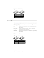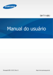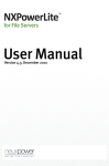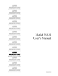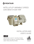
1
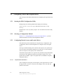
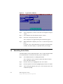
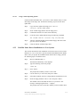
USER’S
GUIDE
Embedded SATA Software
RAID for ICH6R
October 2004
®
DB15-000319-00
Document DB15-000319-00, October 2004
This document describes the initial release of LSI Logic Corporation’s Embedded SATA
Software RAID for ICH6R and will remain the official user’s guide for all
revisions/releases of this product until rescinded by an update.
LSI Logic Corporation reserves the right to make changes to any products herein at any
time without notice. LSI Logic does not assume any responsibility or liability arising out
of the application or use of any product described herein, except as expressly agreed to
in writing by LSI Logic; nor does the purchase or use of a product from LSI Logic
convey a license under any patent rights, copyrights, trademark rights, or any other of the
intellectual property rights of LSI Logic or third parties.
Limited Warranty
LSI Logic provides this publication “as is” without warranty of any kind, either expressed
or implied, including, but not limited to, the implied warranties of merchantability or
fitness for a specific purpose.
Some states do not allow disclaimer of express or implied warranties or the limitation or
exclusion of liability for indirect, special, exemplary, incidental or consequential damages
in certain transactions; therefore, this statement may not apply to you. Also, you may
have other rights which vary from jurisdiction to jurisdiction.
Limitations of Liability
LSI Logic shall in no event be held liable for any loss, expenses, or damages of any kind
whatsoever, whether direct, indirect, incidental, or consequential (whether arising from
the design or use of this product or the support materials provided with the product). No
action or proceeding against LSI Logic may be commenced more than two years after
the delivery of product to Licensee of Licensed Software.
Licensee agrees to defend and indemnify LSI Logic from any and all claims, suits, and
liabilities (including attorney’s fees) arising out of or resulting from any actual or alleged
act or omission on the part of Licensee, its authorized third parties, employees, or agents,
in connection with the distribution of Licensed Software to end-users, including, without
limitation, claims, suits, and liability for bodily or other injuries to end-users resulting
from use of Licensee’s product not caused solely by faults in Licensed Software as
provided by LSI Logic to Licensee.
Disclaimer
LSI Logic certifies only that this product will work correctly when this product is used
with the same system configuration, the same memory module parts, and the same
peripherals that were tested by LSI Logic with this product. The complete list of tested
system configurations, peripheral devices, and memory modules are documented in the
LSI Logic Compatibility Report for this product. Call your LSI Logic sales representative
for a copy of the Compatibility Report for this product.
Copyright © 2004 by LSI Logic Corporation. All rights reserved.
ii
Copyright © 2004 by LSI Logic Corporation. All rights reserved.
TRADEMARK ACKNOWLEDGMENT
LSI Logic, the LSI Logic logo design, and MegaRAID, are trademarks or registered
trademarks of LSI Logic Corporation. Linux is a trademark of Linus Torvalds. Red Hat
is a trademark of Red Hat, Inc. MS-DOS, Windows, and Windows NT are registered
trademarks of Microsoft Corporation. Novell and NetWare are registered trademarks of
Novell, Inc. All other brand and product names may be trademarks of their respective
companies.
To receive product literature, visit us at http://www.lsilogic.com.
For a current list of our distributors, sales offices, and design resource centers, view
our web page located at
http://www.lsilogic.com/contacts/index.html
iii
Copyright © 2004 by LSI Logic Corporation. All rights reserved.
iv
Copyright © 2004 by LSI Logic Corporation. All rights reserved.
Preface
Package Contents
You should have received the following:
•
a Embedded SATA Software RAID for ICH6R User's Guide
•
software license agreement
•
CD/diskette(s) with the software for Embedded SATA Software RAID
This book is the primary reference and user’s guide for the Embedded SATA
Software RAID for ICH6R. Customer specific documentation may be included
as well.
The Embedded SATA Software RAID supports four serial ATA ports, providing
a cost-effective way to achieve higher transfer rates and reliability. The RAID
levels supported are RAID 0, 1, and 10.
Audience
This document was prepared for users of the Embedded SATA Software RAID.
It is intended to provide a description of the product, the configuration software
utilities, and the operating system installation.
Organization
This document has the following chapters:
•
Chapter 1, Overview, provides an overview of features and benefits of the
Embedded SATA Software RAID for ICH6R.
•
Chapter 2, RAID Levels, describes the RAID levels supported by ICH6R.
Embedded SATA Software RAID
Copyright © 2004 by LSI Logic Corporation. All rights reserved.
v
•
Chapter 3, BIOS Configuration Utility, explains how to configure ICH6R
SATA and arrays, assign RAID levels, plan the array configuration,
optimize storage, and use the ICH6R IDE Setup Utility.
•
Chapter 4, Operating System Installation, contains the procedures for
installing the Windows 2000, 2003, and XP, Red Hat Linux, SuSE Linux,
and Novell NetWare operating systems when using the Embedded SATA
Software RAID.
•
Chapter 5, Hyper Configuration Utility, , describes the command line
utility for SATA RAID, which is used to configure and manage RAID
levels.
•
Chapter 6, Spy Service, describes the Spy Service program, which looks for
errors, failed drives, and status changes in the hard drives.
•
Chapter 7, Troubleshooting, describes the problems you might encounter
while using ICH6R and suggests solutions.
Conventions Used in This Manual
The following table describes the notational conventions used throughout
this manual:
Notation
Example
Meaning and Use
courier typeface
.nwk file
Names of commands, directories, filenames, and on-screen text
are shown in courier typeface.
bold typeface
fd1sp
In a command line, keywords are shown in bold, non-italic
typeface. Enter them exactly as shown.
italics
module
In command lines and names, italics indicate user variables.
Italicized text must be replaced with appropriate user-specified
items. Enter items of the type called for, using lower case.
italic underscore
full_pathname
When an underscore appears in an italicized string, enter a usersupplied item of the type called for with no spaces.
Initial Capital letters
Undo
Edit
Apply
Names of menu commands, options, check buttons, text buttons, options buttons, text boxes, list boxes, etc., are shown in
text with Initial Capital lettering to avoid misreading. These elements may appear on your screen in all lower case.
brackets
[version]
You may, but need not, select one item enclosed within brackets. Do not enter the brackets.
ellipses
option...
In command formats, elements preceding ellipses may be
repeated any number of times. Do not enter the ellipses. In
menu items, if an ellipsis appears in an item, clicking that item
brings up a dialog box.
vi
Preface
Copyright © 2004 by LSI Logic Corporation. All rights reserved.
Notation
Example
Meaning and Use
vertical dots
.
.
.
Vertical dots indicate that a portion of a program or listing has
been omitted from the text.
semicolon and other
punctuation
Use as shown in the text.
Preface
Copyright © 2004 by LSI Logic Corporation. All rights reserved.
vii
viii
Preface
Copyright © 2004 by LSI Logic Corporation. All rights reserved.
1.1
1.2
2.1
2.2
2.3
3.1
3.2
3.3
3.4
3.5
3.6
3.7
3.8
4.1
4.2
4.3
RAID Benefits
1-1
1.1.1
Improved I/O
1-1
1.1.2
Increased Reliability
1-2
Product Features
1-2
1.2.1
SATA Ports
1-2
1.2.2
BIOS Features
1-2
1.2.3
Driver Features
1-3
1.2.4
Manageability/Disk Console
1-4
RAID 0
2-1
RAID 1
2-2
RAID 10
2-3
Configuring Arrays
3-1
Configuration Strategies
3-2
Assigning RAID Levels
3-2
Performing a Quick Configuration
3-3
Configuring Arrays and Logical Drives
3-4
3.5.1
Starting the BIOS Configuration Utility
3-4
3.5.2
Selecting a Configuration Method
3-4
3.5.3
Configuring Physical Arrays and Logical Drives
3-4
Physical Drive Parameters
3-4
Logical Drive Parameters
3-5
Easy Configuration
3-5
New Configuration and View/Add Configuration
3-7
3.5.4
Initializing Logical Drives
3-9
Rebuilding Failed Disks
3-10
3.6.1
Inserting a Previously Removed Drive from a RAID 1 Array3-11
Checking Data Consistency
3-11
Using a Pre-loaded System Drive
3-12
Windows 2000/2003/XP Driver Installation
4-1
4.1.1
Updating the Windows 2000/2003/XP Driver
4-2
4.1.2
Confirming the Windows 2000/2003/XP Driver Installation4-2
DOS Driver Installation
4-3
Linux Driver Installation
4-3
4.3.1
Obtaining the Driver Image File
4-3
4.3.2
Preparing the Installation Disk(s) for Linux
4-4
Using a Windows Operating System
4-4
Using a Linux Operating System
4-5
4.3.3
Red Hat Linux Driver Installation on a New System
4-5
ix
Copyright © 2004 by LSI Logic Corporation. All rights reserved.
4.4
5.1
5.2
5.3
5.4
5.5
6.1
6.2
6.3
6.4
6.5
7.1
7.2
4.3.4
SuSE Linux 9.0 Driver Installation on a New System
4-6
4.3.5
SuSE 8.2 Driver Installation
4-7
4.3.6
SuSE SLES8 Driver Installation
4-8
Novell NetWare Driver Installation
4-8
4.4.1
Novell NetWare Driver Files Description
4-8
4.4.2
New Novell NetWare System Driver Installation
4-8
4.4.3
Existing Novell NetWare System Driver Installation
4-10
General Description
5-1
Installing HyperCFG
5-2
Using HyperCFG
5-2
Configuration File
5-8
5.4.1
RAID Information
5-8
5.4.2
Logical Array Information
5-9
5.4.3
Physical Drive Information
5-9
Return Codes on Error Condition
5-10
Starting or Stopping Spy Service under Windows 2000, XP, or 2003 6-1
Installing Spy Service under Linux
6-3
Installing and Running Spy Service under Novell NetWare
6-3
Uninstalling Spy Service
6-4
Spy Service Icon
6-4
Problems and Suggested Solutions
7-1
Embedded SATA Software RAID Problem Report Form
7-2
x
Copyright © 2004 by LSI Logic Corporation. All rights reserved.
3.1
3.2
3.3
5.1
5.2
7.1
7.2
Physical Drives Required per RAID Level
Physical Drives Required per RAID Level
Logical Drive Parameters and Descriptions
HyperCFG Options and Attributes
Return Codes on Error Conditions
Problems and Suggested Solutions
Embedded SATA Software RAID Problem Report Form
3-2
3-3
3-5
5-3
5-10
7-1
7-3
xi
Copyright © 2004 by LSI Logic Corporation. All rights reserved.
xii
Copyright © 2004 by LSI Logic Corporation. All rights reserved.
2.1
2.2
2.3
3.1
3.2
3.3
6.1
RAID 0 Array
RAID 1 Array
RAID 10 Array
Configuration Menu Screen
Logical Drive Configuration Screen
Logical Drive Submenu
Control Panel Screen
2-2
2-2
2-3
3-6
3-7
3-10
6-2
xiii
Copyright © 2004 by LSI Logic Corporation. All rights reserved.
xiv
Copyright © 2004 by LSI Logic Corporation. All rights reserved.
Chapter 1
Overview
This manual describes the Embedded SATA Software RAID for ICH6R. This
chapter provides an overview of this product and contains the following
sections:
•
Section 1.1, “RAID Benefits,” page 1-1
•
Section 1.2, “Product Features,” page 1-2
The Embedded SATA Software RAID supports four Serial ATA ports, providing
a cost-effective way to achieve higher transfer rates and reliability. Embedded
SATA Software RAID supports
1.1
•
RAID level 0 data striping for improved performance
•
RAID level 1 data mirroring for improved data reliability
•
RAID level 10 data striping and mirroring for high data transfer rates and
data redundancy
RAID Benefits
RAID has gained popularity because it can improve I/O performance or
increases storage subsystem reliability. RAID 0 provides better performance,
while RAID 1 provides better reliability through fault tolerance and redundant
data storage. RAID 10 combines both striping and mirroring to provide high
data transfer rates and data redundancy.
1.1.1
Improved I/O
Although hard drive capabilities have improved drastically, actual performance
has improved only three to four times in the last decade. Computing
performance has improved over 50 times during the same time period. RAID 0
and RAID 10 allow you to access several disks simultaneously.
Embedded SATA Software RAID
Copyright © 2004 by LSI Logic Corporation. All rights reserved.
1-1
1.1.2
Increased Reliability
The electromechanical components of a disk subsystem operate more slowly,
require more power, and generate more noise and vibration than electronic
devices. These factors reduce the reliability of data stored on disks.
RAID 1 and RAID 10 systems improve data storage reliability and fault
tolerance compared to single-drive computers. The additional drive in each
RAID 1 array makes it possible to prevent data loss from a hard drive failure.
You can reconstruct missing data from the remaining data drive to a replacement
drive.
1.2
1.2.1
Product Features
SATA Ports
The Embedded SATA Software RAID supports four ports.
1.2.2
BIOS Features
The BIOS features include
1-2
•
RAID support before the operating system loads
•
automatic detection and configuration of disk drives
•
ability to handle configuration changes
•
support for Interrupt 13 and Enhanced Disk Drive Specification
•
support for RAID levels 0, 1, and 10
•
special handling of error log and rebuilding
•
ROM option size of 64 Kbyte
•
automatic resume of rebuilding and check consistency
•
support for BIOS Boot Specification (BBS) (If available in system BIOS,
this allows the user to select the adapter from which to boot. Specification
v1.01, January 11, 1996)
•
co-existence with SCSI and CD devices
•
48-bit LBA support for read, write, and cache flush functions
•
independent stripe size configuration on each logical drive
Overview
Copyright © 2004 by LSI Logic Corporation. All rights reserved.
1.2.3
•
ability to select a logical drive as boot device
•
support for power-on self test (POST) Memory Management (PMM) for the
BIOS memory requirement (Specification v1.01, November 21, 1997)
•
enhanced disk drive support (Specification 2.9, revision 08, March 12,
1998)
•
Industry-standard EBDA
•
Self-monitoring analysis and reporting technology (S.M.A.R.T.) notification
at POST
•
run-time BIOS support for device insertion or removal
•
independent support for WC, RC, and UDMA (direct memory access)
•
support for Stop On Error during bootup
•
support to disable/enable BIOS state
Driver Features
The driver features include
•
special interface for configuration information, configuration changes, and
manageability
•
optimized disk access
•
support for RAID levels 0, 1, and 10
•
support for Stand-by and Hibernation in Windows 2000, XP, and 2003
Note:
The following items require Spy Service to be running in order
to work.
•
error logging in the operating system event log and on disks
•
support for online mirror rebuilding
•
support for check consistency for mirrored disks
•
bootable RAID 0, 1, and 10 support
•
customized messages specific for OEM (original equipment manufacturer)
•
soft bad block management
Product Features
Copyright © 2004 by LSI Logic Corporation. All rights reserved.
1-3
1.2.4
Manageability/Disk Console
The features you can use to manage the logical and physical disks in the system
include
1-4
•
configuration information display (in BIOS Configuration Utility and Hyper
Configuration Utility)
•
support for RAID levels 0, 1, and 10
•
online mirror rebuilding (in BIOS Configuration Utility)
•
online consistency checks (in BIOS Configuration Utility)
•
array management software
•
error logging and notification
•
support for power management features
•
support for hot device insertion and removal
•
automatic resume of rebuilding on restart
•
support for manual rebuild
•
physical drive roaming
•
independent stripe size configuration per logical drive
•
ability to create up to eight logical drives per array
•
auto-configuration support of newly added physical drive
•
support for hotspares
•
support for disk coercion
•
array initialization support (fast and normal)
•
offline data (RAID 1) verfication with auto-recovery mechanism
•
ability to prioritize configurable tasks (for online rebuild, check consistency,
migration, and expansion)
•
logical drive availability immediately after creation
•
variable stripe size options from 8 Kbyte to 128 Kbyte
Overview
Copyright © 2004 by LSI Logic Corporation. All rights reserved.
Chapter 2
RAID Levels
Embedded SATA Software RAID supports RAID levels 0, 1, and 10. These
RAID levels are discussed in the following sections:
2.1
•
Section 2.1, “RAID 0,” page 2-1
•
Section 2.2, “RAID 1,” page 2-2
•
Section 2.3, “RAID 10,” page 2-3
RAID 0
RAID 0 (Figure 2.1) provides disk striping across all configured drives in the
RAID subsystem. RAID 0 does not provide any data redundancy, but does offer
the best performance of any RAID level. RAID 0 breaks up data into smaller
segments, then stripes the data segments across each drive in the array as shown
in Figure 2.1. The size of each data segment is determined by the stripe size
parameter, which is set during the creation of the RAID set.
By breaking up a large file into smaller segments, Embedded SATA Software
RAID can use both IDE ports and drives to read or write the file faster. This
makes RAID 0 ideal for applications that require high bandwidth but do not
require fault tolerance.
Uses
Provides high data throughput, especially for large files. Any
environment that does not require fault tolerance.
Strong Points
Provides increased data throughput for large files. No capacity loss
penalty for parity.
Weak Points
Does not provide fault tolerance. All data lost if any drive fails.
Drives
One to two
Embedded SATA Software RAID
Copyright © 2004 by LSI Logic Corporation. All rights reserved.
2-1
Figure 2.1
RAID 0 Array
Segment 1
Segment 3
Segment 5
Segment 7
2.2
Segment 2
Segment 4
Segment 6
Segment 8
RAID 1
RAID 1 (Figure 2.2) duplicates all data from one drive to a second drive. RAID
1 provides complete data redundancy, but at the cost of doubling the required
data storage capacity.
Uses
Databases or any other mission critical environment that requires
fault tolerance.
Strong Points
Provides complete data redundancy. RAID 1 is ideal for any
application that requires fault tolerance.
Weak Points
Requires twice as many hard drives. Performance is impaired during
drive rebuilds.
Drives
Two
Figure 2.2
Segment 1
Segment 2
Segment 3
Segment 4
2-2
RAID 1 Array
Segment 1 Duplicated
Segment 2 Duplicated
Segment 3 Duplicated
Segment 4 Duplicated
RAID Levels
Copyright © 2004 by LSI Logic Corporation. All rights reserved.
2.3
RAID 10
RAID 10 is a combination of RAID 1 and RAID 0. RAID 10 has mirrored
drives. It breaks up data into smaller blocks, then stripes the blocks of data to
each RAID 1 RAID set. Each RAID 1 RAID set then duplicates its data to its
other drive. The size of each block is determined by the stripe size parameter,
which is set during the creation of the RAID set. RAID 10 can sustain one drive
failure in each array while maintaining data integrity.
Uses
Works best for data storage that must have 100% redundancy of
RAID 1 (mirrored arrays) and that also needs the enhanced I/O
performance of RAID 0 (striped arrays). RAID 10 works well for
medium-sized databases or any environment that requires a higher
degree of fault tolerance and moderate to medium capacity.
Strong Points
Provides both high data transfer rates and complete data
redundancy.
Weak Points
Requires twice as many drives..
Drives
4
Figure 2.3 shows a RAID 10 array with four disk drives.
Figure 2.3
RAID 10 Array
RAID 1
Disk 1
Segment 1
Segment 3
Segment 5
RAID 1
Disk 2
Disk 3
Segment 2
Segment 4
Segment 6
Segment 1
Segment 3
Segment 5
Disk 4
Segment 2
Segment 4
Segment 6
RAID 0
RAID 10
Copyright © 2004 by LSI Logic Corporation. All rights reserved.
2-3
2-4
RAID Levels
Copyright © 2004 by LSI Logic Corporation. All rights reserved.
Chapter 3
BIOS Configuration
Utility
This chapter explains how to configure ICH6R SATA and arrays, assign RAID
levels, plan the array configuration, optimize storage, and use the ICH6R IDE
Setup Utility. This information is presented in the following sections:
3.1
•
Section 3.1, “Configuring Arrays,” page 3-1
•
Section 3.2, “Configuration Strategies,” page 3-2
•
Section 3.3, “Assigning RAID Levels,” page 3-2
•
Section 3.4, “Performing a Quick Configuration,” page 3-3
•
Section 3.5, “Configuring Arrays and Logical Drives,” page 3-4
•
Section 3.6, “Rebuilding Failed Disks,” page 3-10
•
Section 3.7, “Checking Data Consistency,” page 3-11
•
Section 3.8, “Using a Pre-loaded System Drive,” page 3-12
Configuring Arrays
Configure the physical disk drives in arrays. An array can consist of one to four
physical disk drives, depending on the RAID level. A RAID 0 array can consist
of one to four physical drives, while a RAID 1 array consists of two. A RAID
10 array consists of four drives.
Embedded SATA Software RAID
Copyright © 2004 by LSI Logic Corporation. All rights reserved.
3-1
3.2
Configuration Strategies
You have two choices when creating a RAID array.
•
Maximizing Fault Tolerance
You can maximize fault tolerance to protect against loss of data by using
mirroring. Use mirror configuration (RAID 1) to attain this objective.
•
Maximizing Logical Drive Performance
You can maximize logical drive performance by using striping. Select
striping configuration (RAID 0) to attain this objective.
RAID 10 combines both striping and mirroring to provide high data transfer
rates and data redundancy.
3.3
Assigning RAID Levels
Only one RAID level can be assigned to each array. Table 3.1 displays the drives
required per RAID level.
Table 3.1
3-2
Physical Drives Required per RAID Level
RAID Level
Minimum Number of Physical Maximum Number of Physical
Drives
Drives
0
One
Four
1
Two
Two
10
Four
Four
BIOS Configuration Utility
Copyright © 2004 by LSI Logic Corporation. All rights reserved.
The factors you need to consider when selecting a RAID level are listed in
Table 3.2.
Table 3.2
Physical Drives Required per RAID Level
Level
Description and Use
Pros
Cons
Number Fault
of Drives Tolerant
0
Data divided in blocks and
distributed sequentially (pure
striping). Use for non-critical
data that requires high
performance.
High data
throughput for
large files
No fault tolerance. Data is
lost if a drive fails.
One to
four
1
Data duplicated on another disk
(mirroring). Use for readintensive, fault-tolerant
systems.
100 percent data
redundancy,
providing fault
tolerance.
More disk space required. Two
Reduces usable disk space
to the size of the smallest
drive. Reduced performance
during rebuilds.
Yes
10
A combination of RAID 1 (data
mirroring) and RAID 0 (data
striping). Use for mediumsized databases or any
environment that requires a
higher degree of fault tolerance
and moderate to medium
capacity.
Provides both high
data transfer rates
and complete data
redundancy.
More disk space required. Four
Reduces usable disk space
to the size of the smallest
drive. Reduced performance
during rebuilds.
Yes
3.4
No
Performing a Quick Configuration
This section provides quick installation steps for users that are familiar with
configuration utilities and tools. Refer to Section 3.5, “Configuring Arrays and
Logical Drives,” for detailed configuration instructions. To ensure best
performance, select the optimal RAID level for the logical drive you create.
Perform the following steps to configure arrays and logical drives using the
Configuration Utility (CU):
Step 1.
Boot the system.
Step 2.
Start the CU by pressing <Ctrl><M>.
Step 3.
Select a configuration method.
Step 4.
Create arrays using the available physical drives.
Step 5.
Define the logical drive(s) using the space in the arrays.
Step 6.
Initialize the new logical drive(s).
Performing a Quick Configuration
Copyright © 2004 by LSI Logic Corporation. All rights reserved.
3-3
3.5
Configuring Arrays and Logical Drives
This section provides detailed instructions for configuring the logical disks and
arrays.
3.5.1
Starting the BIOS Configuration Utility
During bootup, the following BIOS banner displays the following:
Press Ctrl-M to run LSI Logic Embedded SATA RAID Setup
Utility
Hold down the <Ctrl> key while you press <M>. The main menu for the utility
displays.
3.5.2
Selecting a Configuration Method
Section 3.5.3, “Configuring Physical Arrays and Logical Drives,” provides
detailed instructions for using each configuration method.
3.5.3
Configuring Physical Arrays and Logical Drives
This subsection provides instructions for using the Easy Configuration, New
Configuration, and View/Add Configuration to configure arrays and logical
drives.
LSI Logic recommends using drives with the same capacity in a specific array.
If you use drives with different capacities in an array, the CU treats all these
drives as if they have the capacity of the smallest drive.
The number of physical drives in a specific array determines the possible RAID
levels that you can implement with the array. RAID 0 requires one to four
physical drives, RAID 1 requires two physical drives, and RAID 10 requires
four physical drives.
3.5.3.1
Physical Drive Parameters
You can change the write policy and read policy in the physical drives, but not
the logical drives. You have to reboot for the changes to the write and read
policies to take effect.
3-4
BIOS Configuration Utility
Copyright © 2004 by LSI Logic Corporation. All rights reserved.
3.5.3.2
Logical Drive Parameters
For the logical drive you can change the RAID level and stripe size. Table 3.3
contains descriptions of the logical drive parameters.
Table 3.3
Logical Drive Parameters and Descriptions
Parameter
Description
RAID Level The number of physical drives in a specific array determines the RAID
levels that can be implemented with the array.
RAID 0 requires one or two physical drives.
RAID 1 requires exactly two physical drives.
RAID 10 requires exactly four physical drives.
Stripe Size
The stripe size parameter specifies the size of the segment written to each
disk in a RAID configuration. You can set the stripe size to 4, 8, 16, 32,
64, or 128 Kbytes. The default is 64 Kbytes.
A larger stripe size produces higher read performance. If your computer
regularly performs random read requests, choose a smaller stripe size.
3.5.3.3
Easy Configuration
In Easy Configuration, the CU associates each hard drive with a single logical
drive. If logical drives have already been configured, the CU does not change
their configuration. Perform the following steps to create arrays using Easy
Configuration:
Step 1.
Select Configuration→ Easy Configuration at the main menu.
The Configuration Menu screen displays, as shown in Figure 3.1.
Configuring Arrays and Logical Drives
Copyright © 2004 by LSI Logic Corporation. All rights reserved.
3-5
Figure 3.1
Step 2.
Configuration Menu Screen
Press the spacebar to associate the selected physical drives with the
current array.
The indicator for the selected drives changes from READY to ONLIN
A[array number]-[drive number]. For example, ONLIN
A1-3 means array 1 with disk drive 3.
Step 3.
Press <Enter> after you finish creating the current array.
Step 4.
Press <F10> to select configurable arrays.
Step 5.
Press the spacebar to select the array.
The logical drive configuration screen displays, as shown in Figure 32. The logical drive configuration screen displays the logical drive
number, RAID level, logical drive size, the number of stripes in the
physical array, the stripe size, and the state of the logical drive.
3-6
BIOS Configuration Utility
Copyright © 2004 by LSI Logic Corporation. All rights reserved.
Figure 3.2
Step 6.
Logical Drive Configuration Screen
Set the RAID level for the logical drive by highlighting RAID and
pressing <Enter>.
The available RAID levels for the current logical drive display.
Step 7.
Select a RAID level and press <Enter>.
Step 8.
Set the RAID logical drive size and stripe size.
Step 9.
When you have defined the current logical drive, select Accept and
press <Enter>.
Step 10. Repeat step 7 to step 10 to configure additional logical drives.
Step 11. Save the configuration when prompted and press <Esc> to return to
the Management Menu.
Step 12. Initialize the logical drives.
Refer to Section 3.5.4, “Initializing Logical Drives,” for detailed
instructions.
3.5.3.4
New Configuration and View/Add Configuration
New Configuration and View/Add Configuration associate logical drives with
partial and/or multiple physical arrays. New Configuration deletes the existing
configuration and replaces it with the configuration that you specify. View/Add
Configuration lets you display or modify an existing configuration.
Caution:
The New Configuration option erases the existing
configuration data when you save the new array
Configuring Arrays and Logical Drives
Copyright © 2004 by LSI Logic Corporation. All rights reserved.
3-7
configuration. If you do not want to delete the existing
configuration data, use View/Add Configuration.
Perform the following steps to configure a disk array using New Configuration
or View/Add Configuration:
Step 1.
Select Configure→ View/Add Configuration from the CU
Management Menu.
The CU displays an array selection window.
Step 2.
Select the physical drives to include in the array by pressing the arrow
keys to select specific physical drives.
Step 3.
Press the spacebar to associate the selected physical drive with the
current array.
The indicator for the selected drive changes from READY to ONLIN
A[array number]-[drive number]. For example, ONLIN
A1-3 means array 1 with disk drive 3.
Step 4.
Press <Enter> after you finish creating the current array.
Step 5.
Press <F10> to configure logical drives.
Step 6.
Set the RAID level for the logical drive by highlighting RAID and
pressing <Enter>.
A list of the available RAID levels for the current logical drive
appears.
Step 7.
Set the logical drive size by moving the cursor to Size and pressing
<Enter>.
By default, the logical drive size associates the available space in the
array(s) with the current logical drive.
Step 8.
Set the stripe size.
Step 9.
After you define the current logical drive, select Accept and press
<Enter>.
Step 10. Save the configuration when the CU prompts you to do so.
Step 11. Initialize the logical drives you configured. Section 3.5.4, “Initializing
Logical Drives,” provides detailed instructions.
3-8
BIOS Configuration Utility
Copyright © 2004 by LSI Logic Corporation. All rights reserved.
3.5.4
Initializing Logical Drives
You can initialize the logical drives using individual initialization, which
initializes a single logical disk.
There are two methods to initialize a logical drive using the individual
initialization procedure using the CU.
For the first method, perform the following steps to initialize a logical drive
using the Initialize menu.
Step 1.
On the Management Menu, select Initialize.
Step 2.
Use the space bar to highlight the logical drive to initialize.
The logical drive name is highlighted in yellow. To de-select the
logical drive, press the space bar again.
Step 3.
Press <F10>.
Step 4.
Select Yes at the prompt and press <Enter> to begin the initialization.
A graph shows the progress of the initialization until it is complete.
Step 5.
After the initialization is complete, press <Esc> to return to previous
menus.
If you press <Esc> while initialization is in progress, the following
options display:
◊
Stop: The CU stores the percentage of the initialization already
completed. When you restart initialization, it continues from the
last percentage completed rather than from zero percent.
◊
Continue: initialization continues normally.
◊
Abort: The initialization is completely aborted. If you restart
initialization, it begins at zero percent.
For the second method, perform the following steps to initialize a logical drive
using the Objects menu.
Step 1.
From the Management Menu, select Objects→ Logical Drive
submenu, as shown in Figure 3.3.
The configured logical drives display.
Configuring Arrays and Logical Drives
Copyright © 2004 by LSI Logic Corporation. All rights reserved.
3-9
Figure 3.3
Logical Drive Submenu
Step 2.
Select a logical drive, if there is more than one configured. and press
<Enter>.
Step 3.
Select Initialize from the submenu and press <Enter>.
Step 4.
Select Yes at the prompt and press <Enter>.
The CU displays a bar graph showing the initialization progress.
Step 5.
When initialization completes, press <Esc> to return to the previous
menu.
If you press <Esc> while initialization is in progress, the options Stop,
Continue, and Abort display, as explained on the previous page.
3.6
Rebuilding Failed Disks
A manual rebuild is used to rebuild failed drives. The CU allows manual rebuild
for an individual drive. Perform the following steps to rebuild a drive:
Step 1.
Select Rebuild from the CU Management Menu.
The CU displays a device selection window that marks the failed
drives with FAIL indicators.
3-10
Step 2.
Press the arrow keys to highlight the drive to be rebuilt.
Step 3.
Press the spacebar to select the highlighted physical drive for rebuild.
Step 4.
After selecting the physical drive, press <F10> and select Yes at the
confirmation prompt.
BIOS Configuration Utility
Copyright © 2004 by LSI Logic Corporation. All rights reserved.
The indicators for the selected drive changes to REBLD.
Step 5.
When rebuild is complete, press any key to continue.
Step 6.
Press <Esc> to display the Management Menu.
A second way to perform a manual rebuild on an individual drive is as follows:
3.6.1
Step 1.
Select the option from the CU→ Objects→ Physical Drive submenu.
Step 2.
Press the arrow keys to select the physical drive to be rebuilt and
press <Enter>.
Step 3.
Select the Rebuild option from the action menu and respond to the
confirmation prompt.
Step 4.
When rebuild completes, press any key to display the previous menu.
Inserting a Previously Removed Drive from a RAID 1 Array
If you have auto-rebuild selected in the BIOS, the rebuild begins as soon as you
enter the BIOS CU. If auto-rebuild is disabled, you can choose whether to
rebuild. If you decide to rebuild the drive, follow the procedure in Section 3.6,
“Rebuilding Failed Disks,” page 3-10.
3.7
Checking Data Consistency
The Check Consistency feature verifies the correctness of the redundancy data
in the selected logical drive and causes the CU to automatically correct any
differences found in the data.
This feature can be used only on a RAID 1 logical drive, to verify the data
consistency between the mirrored physical drives. When a data inconsistency is
found, the CU can either only report the inconsistency or report and fix the
inconsistency, depending upon the option selected in Adapter settings.
In the CU, perform the following steps to check consistency:
Step 1.
On the Management Menu select Check Consistency and press
<Enter>.
The configured logical drives display.
Step 2.
Use the space bar to select a logical drive to check for consistency.
Checking Data Consistency
Copyright © 2004 by LSI Logic Corporation. All rights reserved.
3-11
Note that the logical drive should be at a RAID 1 level to start check
consistency. If you select a RAID 0 logical drive, a message displays
stating that a check consistency cannot be performed. To de-select a
logical drive, press the space bar again.
Step 3.
Press <F10>.
Step 4.
At the prompt, select Yes to start check consistency and press
<Enter>.
If you press <Esc> while the check consistency is in progress, the
following options display:
3.8
◊
Stop: The CU stores the percentage of the check consistency
already completed. When you restart the check consistency, it
continues from the last percentage completed rather than from zero
percent.
◊
Continue: Check consistency continues normally.
◊
Abort: The check consistency is completely aborted. If you restart
check consistency, it begins at zero percent.
Using a Pre-loaded System Drive
You can use the controller as an adapter for this drive by performing the
following steps:
Step 1.
Connect the drive to the port on the controller.
Step 2.
Boot the computer.
Step 3.
Start the CU.
Step 4.
Select Configure→ Easy Configuration from the menu.
Step 5.
Press the cursor keys to select the pre-loaded drive.
Step 6.
Press the spacebar.
The pre-loaded drive now becomes an array element.
Step 7.
Press <Enter>. The pre-loaded drive is a one-disk array.
Step 8.
Display the logical drive configuration screen.
Step 9.
Highlight Accept and press <Enter>.
Step 10. Press <Esc> and select Yes at the prompt to save the configuration.
3-12
BIOS Configuration Utility
Copyright © 2004 by LSI Logic Corporation. All rights reserved.
Step 11. Press <Esc> to exit the CU and reboot.
Step 12. Set the host system to boot from the drive.
Some operating systems treat RAID storage adapters as mass storage devices.
Using a Pre-loaded System Drive
Copyright © 2004 by LSI Logic Corporation. All rights reserved.
3-13
3-14
BIOS Configuration Utility
Copyright © 2004 by LSI Logic Corporation. All rights reserved.
Chapter 4
Operating System
Installation
This chapter contains the procedures for installing the Windows 2000, 2003, and
XP, Red Hat Linux, SuSE Linux, and Novell NetWare operating systems when
using the Embedded SATA Software RAID. The chapter contains the following
sections:
4.1
•
Section 4.1, “Windows 2000/2003/XP Driver Installation,” page 4-1
•
Section 4.2, “DOS Driver Installation,” page 4-3
•
Section 4.3, “Linux Driver Installation,” page 4-3
•
Section 4.4, “Novell NetWare Driver Installation,” page 4-8
Windows 2000/2003/XP Driver Installation
Perform the following steps to install the Windows 2000 or 2003 driver onto the
RAID-configured drives.
Step 1.
Boot the system with the Windows 2000 or 2003 Boot Installation CD
or diskette.
The following message displays:
Setup is inspecting your computers hardware
configuration.
Next, a prompt displays.
Step 2.
At the prompt, press <F6> to install the RAID/SCSI adapter driver.
Step 3.
When installation prompts for a key after copying some files, press
<S> to add the SATA RAID driver.
You are prompted for the driver diskette.
Step 4.
Insert the Embedded SATA Software RAID driver floppy diskette and
press <Enter>.
Embedded SATA Software RAID
Copyright © 2004 by LSI Logic Corporation. All rights reserved.
4-1
4.1.1
Step 5.
Scroll down the list until the appropriate selection for your system
which contains the Embedded SATA Software RAID and for your
operating system displays, then click <OK>.
Step 6.
Continue with the normal installation procedure.
Updating the Windows 2000/2003/XP Driver
Perform the following steps to update the Windows 2000 or 2003 driver or
install the Windows 2000 or 2003 driver into an existing system booted from a
standard IDE drive.
Step 1.
Click the Windows Start button.
The Windows menu displays.
Step 2.
Select Settings.
The Settings menu displays to the right.
Step 3.
Click Control Panel.
The Control Panel window displays.
Step 4.
Select Adapters.
Step 5.
Select the Drivers tab.
Step 6.
Scroll down the list until the appropriate selection for your system
which contains the Embedded SATA Software RAID and for your
operating system displays, then click <OK>.
Step 7.
Select it, then remove it by clicking the Remove button.
Step 8.
Click the Add button.
Step 9.
Select the Have Disk button.
Step 10. Insert the diskette into the floppy drive.
Step 11. Select drive letter A: and click on <OK>.
Step 12. Select LSI Logic Embedded SATA Controller and click OK.
Step 13. After Windows NT or Windows 2000 copies the driver, reset the
system.
4.1.2
Confirming the Windows 2000/2003/XP Driver Installation
Perform the following steps to confirm that the Windows 2000, 2003, or XP
driver is installed properly.
4-2
Operating System Installation
Copyright © 2004 by LSI Logic Corporation. All rights reserved.
Step 1.
Click the Windows Start button.
The Windows menu displays.
Step 2.
Select Settings.
The Settings menu displays to the right.
Step 3.
Click Control Panel.
The Control Panel window displays.
Step 4.
Select Adapters.
Step 5.
Select the Drivers tab.
The controller appears in the list as LSI Logic Embedded SATA
Controller.
Step 6.
Select the Devices tab.
One or more entries display as LSI Logic Embedded SATA #xx under
LSI Logic Embedded SATA Controller.
4.2
DOS Driver Installation
For DOS, no driver installation is required. The ROM BIOS contains the lowlevel driver that is necessary for MS-DOS.
4.3
Linux Driver Installation
This section explains how you can make fresh installations of Red Hat and SuSE
Linux operating systems with the Linux Embedded Software Stack driver.
4.3.1
Obtaining the Driver Image File
The driver is offered in the form of a driver update disk. The required file is
dud-<driver version>.img, which is the driver update disk for the
Embedded SATA software RAID stack.
You can obtain the latest driver files from the Download Center on the LSI
Logic web site at: http://www.lsilogic.com.
DOS Driver Installation
Copyright © 2004 by LSI Logic Corporation. All rights reserved.
4-3
4.3.2
Preparing the Installation Disk(s) for Linux
This section describes how to prepare the installation disk(s) from the obtained
driver image files using the Windows- or Linux-based operating systems. Refer
to this section when necessary during installation of Windows and Linux
operating systems.
4.3.2.1
Using a Windows Operating System
Under Windows, you can use the rawrite floppy image writer utility to create
disk images from image files. The image writer can be downloaded from the
Internet. Perform the following steps to build installation diskettes.
Step 1.
Copy the driver update disk image dud-<driver
version>.img and the file rawrite.exe to a directory.
Step 2.
Confirm that the files are in the selected directory.
Step 3.
After you confirm the files, you might need to change the filename of
the driver update disk to a smaller name with less than eight
characters.
Step 4.
Copy dud-<driver version>.img dud.img.
Step 5.
Type the following command to create the two installation diskettes:
RAWRITE
then press <Enter>.
You are prompted to enter the name of the boot image file.
Step 6.
Type:
dud.img
You are prompted for the target drive diskette.
Step 7.
Insert a floppy diskette into the floppy drive and type:
A:
then press <Enter>.
4-4
Step 8.
After the command prompt returns and the floppy disk drive LED
goes out, remove the diskette.
Step 9.
Label the diskette with the image name.
Operating System Installation
Copyright © 2004 by LSI Logic Corporation. All rights reserved.
4.3.2.2
Using a Linux Operating System
Under Red Hat and SuSE Linux, you can use a driver diskette utility to create
disk images from image files. Perform the following steps create the driver
update disk:
Step 1.
Copy the driver update disk image dud-<driver
version>.img to a Linux system.
Step 2.
Insert a blank floppy diskette into the floppy drive.
Step 3.
Confirm that the files are in the selected directory.
Step 4.
Create the driver update diskette using the following command:
dd if=dud-<driver version>.img of=/dev/fd0
4.3.3
Step 5.
After the command prompt returns and the floppy disk drive LED
goes out, remove the diskette.
Step 6.
Label the diskette with the image name.
Red Hat Linux Driver Installation on a New System
This section describes the fresh installation of the device driver on new Linux
Red Hat 3.0, 8.0, 9.0, and AS2.1 systems with the Embedded Software RAID
Stack. After you prepare the installation disks with the driver image, perform
the following steps to install the driver:
Step 1.
Boot to CD-ROM (Disk 1).
The Red Hat introductory screen displays.
Step 2.
Type the following at the boot prompt:
linux dd
Step 3.
Press <Enter>.
The prompt asks whether you have a driver disk.
Step 4.
Use the arrow key to select Yes, then press <Enter>.
Step 5.
Select fd0 to indicate you have a floppy diskette with the driver on it.
Step 6.
Insert the floppy diskette in the A:/ drive and press <Enter>.
The installer locates and loads the driver for your device. The
message “Loading megaide driver...” displays.
The prompt at the next screen asks whether you have another driver.
Linux Driver Installation
Copyright © 2004 by LSI Logic Corporation. All rights reserved.
4-5
4.3.4
Step 7.
Follow the Red Hat Linux installation procedure to complete the
installation.
Step 8.
Reboot the system.
SuSE Linux 9.0 Driver Installation on a New System
This section describes the fresh installation of a Linux SuSE 9.0 system with the
Embedded Software RAID Stack. Prepare installation disks with the driver
image, then perform the following steps to install the driver:
Step 1.
Boot your system using the SuSE 9.0 CD 1.
Step 2.
At the prompt, press <F3> to confirm that you have a driver diskette.
Step 3.
Highlight Installation on the menu using the arrow keys, then press
<Enter>.
You are prompted for the diskette.
Step 4.
Insert the driver update disk in the A:/ drive and press <Enter>.
The message “Driver Updates added” displays.
Step 5.
Press <Enter>.
You are prompted to select the Driver Update Medium.
Step 6.
Select Back and press <Enter>.
This returns you to the installation.
Step 7.
Press <Accept>.
The driver installation begins.
Step 8.
Press <Accept> again.
A warning screen displays to make sure you want to continue the
installation with these settings.
4-6
Operating System Installation
Copyright © 2004 by LSI Logic Corporation. All rights reserved.
Step 9.
Select Yes and complete the installation
Important:
After all the selected packages are installed, a prompt
displays and gives you 10 seconds to reply. If you do not reply
within 10 seconds, you will have to start the installation
process over.
Step 10. Select Stop before the 10 seconds are up.
Step 11. Press <Ctrl> <Alt> <F2>.
This opens a terminal you can use to run a script.
Step 12. At the prompt, type:
cd update/000/install
Step 13. Press <Enter>.
Step 14. Next, type:
./update.post
Step 15. Press <Enter>.
Step 16. At the prompt, press <Ctrl> <Alt> <F7>.
The YaST screen displays.
Step 17. Select <OK>, then press <Enter>, and reboot the system.
4.3.5
SuSE 8.2 Driver Installation
This section describes a fresh installation on a Linux SuSE 8.2 system with the
Embedded Software RAID Stack. Prepare installation disks with the driver
image, then perform the following steps to install the driver:
Step 1.
Create a RAID array using the BIOS.
Step 2.
Boot your system using the SuSE Disk 1.
Step 3.
When the first screen displays, press <F3> and select the installation
menu option.
Step 4.
Insert the driver update disk when prompted.
Step 5.
Complete the installation process and reboot the system.
Linux Driver Installation
Copyright © 2004 by LSI Logic Corporation. All rights reserved.
4-7
4.3.6
SuSE SLES8 Driver Installation
This section describes a fresh installation on a Linux SuSE SLES8.0 system with
the Embedded Software RAID Stack. Prepare installation disks with the driver
image, then perform the following steps to install the driver:
4.4
Step 1.
Create a RAID array using the BIOS.
Step 2.
Boot your system using the SuSE SLES8 1.0 Disk 1.
Step 3.
When the first screen displays, press <Alt> and select the installation
menu option.
Step 4.
Insert the driver update disk when prompted.
Step 5.
Complete the installation process and reboot the system.
Novell NetWare Driver Installation
The section provides installation instructions for the Novell Netware driver.
4.4.1
Novell NetWare Driver Files Description
The Novell NetWare driver and utilities support logical drives configured on the
controller.
Important:
The logical drives configured on the host adapter are registered
with the operating system as separate logical units.
All utilities and spy.nlm expect the driver to pass the requests to the adapter. You
must load the .HAM driver files first, so that it can load the .NLM files.
4.4.2
New Novell NetWare System Driver Installation
Follow the instructions in the Novell NetWare Installation Guide to install
NetWare on the server. Follow these steps to install Novell NetWare using the
controller as a primary adapter:
Step 1.
Boot with the NetWare 6.5 CD-ROM.
Step 2.
Follow the instructions on the screen to select the language and accept
the license.
The Welcome screen displays. The screen message Is this a
default install or manual install? displays.
4-8
Operating System Installation
Copyright © 2004 by LSI Logic Corporation. All rights reserved.
Step 3.
Highlight Default using the arrow keys, then press <Enter> to change
the option to Manual.
Step 4.
Highlight Continue and press <Enter>.
The screen used to prepare the boot partition displays.
Step 5.
Highlight Free Space, then press <Enter>.
Step 6.
Accept the default (500 MB) or modify as desired, then press
<Enter>.
Step 7.
Highlight Continue, then press <Enter>.
The Server Settings screen displays. You can modify the settings
before going to the next screen.
Step 8.
Highlight Continue, then press <Enter>.
The system goes through device driver detection, then the screen
displays the device type and driver name. You can modify the device
type and driver name.
Step 9.
Press Continue, then press <Enter>.
The driver names display.
Step 10. Select Storage adapters using the arrow keys and press <Enter>.
Step 11. Highlight IDEATA.HAM Standard ATA/IDE RAID Adapter
Controller in the list of files.
Step 12. Press <Delete> to remove the highlighted filename.
Note:
Do not highlight IDEATA.HAM Standard
ATA/IDE/ATAPI Adapter Controller in the list of
files; it is needed for the ATAPI CD-ROM drive to operate.
Step 13. Press <Insert> to add a driver.
Step 14. Press <Insert> again.
Step 15. If you have the driver on a diskette, insert it in the A:/ drive.
The install program automatically searches for the driver on the A:/
drive.
Step 16. If you do not have the driver on a diskette, enter the path for the file.
Step 17. Press <Enter>.
The Intel RAID controller displays. There is one driver per controller
to remove or add.
Novell NetWare Driver Installation
Copyright © 2004 by LSI Logic Corporation. All rights reserved.
4-9
Step 18. Press <Esc> twice.
Step 19. Select Continue and press <Enter>.
The storage devices and driver names display so you can match the
drivers to the hardware devices.
Step 20. Select Continue and press <Enter>.
Step 21. Select Continue and press <Enter> again.
The message “Loading driver” displays, then the screen Create Sys
Volume displays.
Step 22. Select Create and press <Enter>.
The Main Menu displays.
Step 23. Select Continue Installation and press <Enter>.
The File Copy Status displays to confirm that the driver files are
installed, then a GUI prompt displays.
Step 24. Select Customized and press <Next>.
Step 25. Continue the normal operating system installation.
4.4.3
Existing Novell NetWare System Driver Installation
Follow these steps to add the NetWare driver to an existing installation.
Step 1.
For NetWare 5.1 and higher, type the following at the root prompt:
nwconfig
4-10
Step 2.
Press <Enter>.
Step 3.
The Configuration Options screen displays.
Step 4.
Select Drive Options and press <Enter>. A window displays.
Step 5.
Select Configure Disk and Storage Device Options and press <Enter>.
Step 6.
Select one of the following options that display in the window:
◊
Discover and Load an Additional Driver
◊
Select an Additional Driver
Step 7.
If you select Discover and Load an Additional Driver, the system
discovers the extra unit and prompts you to select a driver from the
list.
Step 8.
Press <Insert> to insert the driver.
Operating System Installation
Copyright © 2004 by LSI Logic Corporation. All rights reserved.
This completes the procedure.
If you choose Select an Additional Driver, the Select a Driver screen displays.
Perform the following steps to select an additional driver.
Step 1.
Press <Insert>, then follow the instructions that appear.
Step 2.
Insert a diskette into the A:/ drive and press <Enter>.
The system finds the driver and installs it.
Novell NetWare Driver Installation
Copyright © 2004 by LSI Logic Corporation. All rights reserved.
4-11
4-12
Operating System Installation
Copyright © 2004 by LSI Logic Corporation. All rights reserved.
Chapter 5
Hyper Configuration
Utility
HYPERCFG is a command line utility for ICH6R software. This chapter details
the product features in these sections:
5.1
•
Section 5.1, “General Description,” page 5-1
•
Section 5.2, “Installing HyperCFG,” page 5-2
•
Section 5.3, “Using HyperCFG,” page 5-2
•
Section 5.4, “Configuration File,” page 5-8
•
Section 5.5, “Return Codes on Error Condition,” page 5-10
General Description
HYPERCFG is a command line utility for SATA RAID. The main features
supported in this utility are:
•
ability to create RAID arrays
•
ability to save RAID configuration information to file
•
ability to display RAID configuration data
•
ability to configure RAID from file
•
display of RAID option ROM version
•
ability to read and display specified sector from drive
•
ability to add error code information
•
ability to dump identify device command packet
•
self-monitoring analysis and reporting technology (S.M.A.R.T.) option
•
ability to set disk coercion
•
ability to rebuild failed drives
Embedded SATA Software RAID
Copyright © 2004 by LSI Logic Corporation. All rights reserved.
5-1
5.2
Installing HyperCFG
Perform the following steps to install HyperCFG:
Step 1.
Copy the HyperCFG executable file from the CD to your hard drive.
The filename in the various operating systems is:
Step 2.
–
HYPERCFG.exe for DOS
–
hypercfg for Linux
–
HyperWin.exe for Windows
Run the file from the hard drive.
The HyperCFG utility displays. Use the options in Section 5.3, “Using
HyperCFG” to set the RAID configuration and other options.
5.3
Using HyperCFG
The following is a list of options for the utility:
•
Configuration options
•
Drive ID
•
Display options
•
Miscellaneous options
•
Filename
Table 5.1 describes the attributes that you can set for these options.
5-2
Hyper Configuration Utility
Copyright © 2004 by LSI Logic Corporation. All rights reserved.
Table 5.1
HyperCFG Options and Attributes
Options
Description
/S
Silent Operation. When this option is set, the utility does not prompt the user.
/F[File
Name]
This option redirects the output to the specified filename.
If the filename is not specified, then the filename defaults to HyperCFG.CFG.
/L [/C<n>][/D<cd>]
[/B[Filename]]
Displays the configuration sector of the specified drive <Drive-ID>
Using only /L displays the configuration sector from the first available
drive.
Use [/B[Filename]] to dump the IRCD as bin file.
If the filename is not specified, the default filename is
hypercfg.bin.
/E[o][/C<n>][/D<cd>] Erases the configuration sector of the specified drive <Drive-ID>
The [o] field can be any of the following:
/@/b<bfn>
C
Erases the configuration sector only
E
Erases the error log sector only
A
Erases both configuration and error log sectors
Configures the RAID array from the specified configuration file.
If the filename is not specified, the default filename is
hypercfg.bin.
Using HyperCFG
Copyright © 2004 by LSI Logic Corporation. All rights reserved.
5-3
Table 5.1
HyperCFG Options and Attributes (Cont.)
Options
Description
/A[Array]
(for new
configuration)
This option is used to configures arrays for RAID 0, 1, and 10
<m>:d1, d2...dn
/G<n>:<size>
or
<m> is the RAID mode for configuring. The <m> field can be any of
the following three options.
m=S[n]
Means the arrays are configured as RAID 0.
S[n] equals stripe size.
The allowed stripe sizes are 4 Kbytes, 8 Kbytes, 16
Kbytes, 32 Kbytes, 64 Kbytes, 128 Kbytes, 256 Kbytes,
512 Kbytes, 1024 Kbytes, 2048 Kbytes, and 4096
Kbytes.
add/A[Array]
(for add
configuration)
m=M
Means the arrays are configured as RAID 1.
S[n] equals stripe size.
m=R[n]
Means the arrays are configured as RAID 10.
S[n] equals stripe size.
d1, d2...dn are the drive IDs that participate in the array.
<n> is an optional feature that specifies the type of RAID mode for
multiple/mixed mode RAID creation. It is restricted to RAID 0 and
RAID 1. If you select RAID 0 or RAID 1, the default RAID mode will
be overridden. If you do not specify a value for <n>, the default RAID
mode will be used. The <m> field can be any of the following two
options.
n=s
Selects RAID 0 as the RAID level.
n=m
Selects RAID 1 as the RAID level.
<size> represents the size in Mbytes of the logical drive to be created.
1. Note: The logical drive size displays in DEC format.
Initialization
/init/l<n1> /l<n2>...
This option is used to initialize a newly configured logical drive.
/init
Specifies the initialize option.
/1n1> /l<n2>... Specifies the logical drive numbers.
Rebuilding
Check
Consistency
/rbld /d<nn>
This option is used to rebuild a failed hard drive.
/rbld
Specifies the rebuild option.
/d<nn>
Specifies the connection ID for the physical drive.
/ccon/1<n1> /l<n2>... This option is used to perform a consistency check of the logical drives.
/ccon/
Specifies the check consistency option.
/1<n1>/l<n2>.. Specifies the logical drive numbers.
5-4
Hyper Configuration Utility
Copyright © 2004 by LSI Logic Corporation. All rights reserved.
Table 5.1
HyperCFG Options and Attributes (Cont.)
Options
Description
Free Array
Information
/freearr/a<m>:d1, d2,
dn...
Force a Physical /pdstate /d<nn>
Drive Online or /<on/off>
Offline
Adapter
Information
/adp /c<n>
This option is used to access the free array information.
/freearr/a
Specifies the free array information option.
<m>
Specifies the RAID level you need to create.
d1, d2, dn...
Lists the drives.
This option is used to force a physical drive online or offiline.
/pdstate
Specifies the physical drive state option.
/d<nn>
Specifies the connection ID for the physical drive.
/<on/off>
Specifies whether to force the drive online or offline.
This option is used to access adapter information.
/adp
Specifies the adapter information option.
/c<n>
Specifies the controller number.
Using HyperCFG
Copyright © 2004 by LSI Logic Corporation. All rights reserved.
5-5
Table 5.1
HyperCFG Options and Attributes (Cont.)
Options
Description
Adapter
Properties
/SetADP /C<n>
[/r<val>] [/d<val>]
[/b<val>] [/s<val>]
[/n<val>] [/f<val>]
[/c<val>] [/ars<val>]
[/boot<val>]
[/arb<val>]
5-6
This option is used to select values for adapter properties.
/SetADP
Specifies the adapter properties option.
/C<n>
Specifies the controller number.
[/r<val>
Specifies the rebuild rate for the controller. <val> is
from 0 - 100%. This setting is optional.
[/d<val>]
Specifies the disk coercion value. <val> is 0 for none,
1 for 1Gbyte, 2 for 128 Mbyte, and 3 for 10 Gbyte.
[/b<val>]
Specifies whether to enable or disable the BIOS. <val>
is 0 for enable or 1 for disable.
[/s<val>]
Specifies a BIOS setting. <val> is 0 for enable or 1 for
disable.
[/n<val>]
Specifies the action to take if a new device is found. <
<val> is 0 for auto-configuration as a spare or R0/1??
to force into the BIOS Configuration Utility.
[/f<val>]
Specifies whether to enable or disable the fast
initialization of logical drives for the adapter. <val> is
0 for disable or 1 for disable.
[/c<val>]
Specifies the action to be taken during a check
consistency operation. <val> is 0 for fix and report or
1 for report only.
[/ars<val>]
Specifies whether to enable or disable the ability to
resume an incomplete rebuild. <val> is 0 for disable
and 1 for enable.
[/boot<val>]
Specifies the number of the logical drive that you can
boot from. <val> is the logical drive number.
[/arb<val>]
Specifies whether to enable or disable the ability to
perform automatic rebuilds. <val> is 0 for enable and 1
for disable.
Hyper Configuration Utility
Copyright © 2004 by LSI Logic Corporation. All rights reserved.
Table 5.1
Options
HyperCFG Options and Attributes (Cont.)
Description
Display Options This option determines how the data displays. This option is valid only for /I.
/W[o]
Prints the dump for the /I option.
The [o] field can be either of the following:
V
Prints the dump in Verbose mode
Default option: If [o] is not specified, then data displays as a HEX
dump.
/F<fn>
Redirects the output to a file ‘fn’ (for filename). The default filename is
hypercfg.bin.
/Y[x][fn]
Logs to the given filename ‘fn’.
The default for ‘x’ is ‘f’. The default filename is hypercfg.bin.
The [x] field can be either of the following:
f
Logging is done only for errors. This is the default.
c
Continuous logging is done.
1. Note: The exit code can be modified using the qualifier /Q. When /Q is specified, configuration-related commands return ARRAY COUNT on SUCCESS. In all other cases, ERROR LEVEL is returned. All the other
options except /S, /F, /$, /B, /@, and /W have the default argument as zero.
/C[n] /D[cd]
[Drive ID]
/C[n] /D[cd] specifies the drive ID.
/C[n]
Specifies the card number where the drive is present.
[n] is the card index, starting at 0, 1, 2...
/D[cd]
Selects drive for /R, /I, /L, /E, and /P options.
Possible values are as follows:
/C[n] /D[cd]
[/B[Filename]]
[/$[Filename]]
c
Port Number (0 or 1)
d
Device ID (0 or 1)
If ‘n’ is not specified then the sector number is 0.
/B dumps the specified sector to the specified file in BIN format.
/$ dumps the specified BIN file to the “nth” sector.
The default filename is hypercfg.bin.
/I[a] [/C[n]] [/D[cd]]
[/B[Filename]]
Displays identify device packet for specified drive.
/Ia
Displays ID Device Packet for all drives present.
/B[Filename]
Specifies to dump the 512 byte identify data to
filename.
/B option should not be specified with /Ia switch.
/P[s][/C<n>][/D<cd>] Switches the drive to the specified power state. The default is powered
on in the Active state.
The possible value for [s] is:
[s] = S
The drive is powered on in the Suspend state.
Using HyperCFG
Copyright © 2004 by LSI Logic Corporation. All rights reserved.
5-7
Table 5.1
HyperCFG Options and Attributes (Cont.)
Options
Description
/M[R/<MaxAddress>][ This option sets the maximum user-accessible sector address for the
/C<n>][/D<cd>]
specified drive. The address is specified in hexadecimal format.
/Mr
Miscellaneous
Options
Resets the maximum address to the native maximum
address of the specified drive.
This attribute is reserved for miscellaneous options.
/S
Executes in Silent mode.
/V
Detects the presence of RAID BIOS and displays the BIOS version.
/X
Pauses execution if an error occurs.
/Z[/E/D]
Enables/disables S.M.A.R.T. feature. The default is ENABLE. S.M.A.R.T. monitors hard drives
for drive failures.
5.4
Configuration File
The configuration file contains three logical blocks with RAID, logical drive,
and physical drive information. The configuration file is binary and cannot be
read or changed like a normal text file. It is not case sensitive and ignores white
spaces and tabs. The configuration file contains three logical blocks in the
specified order:
5.4.1
1.
RAID INFO
2.
LOGICAL DRIVE INFO
3.
PHYSICAL DRIVE INFO
RAID Information
This logical block starts with the keyword TOTAL_LOGICAL_ARRAYS and
must be organized as follows:
TOTAL_LOGICAL_ARRAYS
:<Number of Arrays>
TOTAL_PHYSICAL_DRIVES
:<Number of Physical Drives>
OPTIONS :
5-8
<+/-WRITE_CACHE
+/-VIRUS_PROTECTION
+/-DMA_ENABLED>
Hyper Configuration Utility
Copyright © 2004 by LSI Logic Corporation. All rights reserved.
The valid choices for the OPTIONS field are as follows:
•
WRITE_CACHE (sets the type of write policy)
•
VIRUS_PROTECTION (selects virus protection)
•
DMA_ENABLED (enables direct memory access)
A “+” prefix to the option value sets the option and a “-” resets the option.
5.4.2
Logical Array Information
This logical block contains the logical drive parameters, which include the
RAID mode (RAID0 = stripe; RAID1=mirror), the size of the stripes, number
of stripes, and number of physical drives in the array. This block starts with the
keyword LOGICAL_ARRAY and must be organized as follows:
5.4.3
LOGICAL_ARRAY
:<Array Number>
RAID_MODE
:<STRIPE/MIRROR>
STRIPE_SIZE
:<STRIPE SIZE>
TOTAL_STRIPES
:<Number of Stripes>
TOTAL_PHYSICAL_DRIVES
:<Number of Physical Drives in Array>
Physical Drive Information
This logical block contains the physical drive number, drive ID, and drive size.
It starts with the keyword PHYSICAL_DRIVE and must be organized as
follows:
PHYSICAL_DRIVE
:<Drive Number>
DRIVE_ID
:<Drive ID>
DRIVE_SIZE
:<Drive Size>
The logical blocks can be separated by blank lines. There can be any number of
blank lines. The lines within the logical block must be consecutive. Blank lines
are not allowed within the logical block. There are as many PHYSICAL DRIVE
INFO blocks as the number of drives participating in the array. All the
PHYSICAL DRIVE INFO blocks for a logical array must follow the LOGICAL
ARRAY INFO block before the start of next LOGICAL ARRAY INFO block.
SPARE ARRAY information cannot be included in the configuration file.
Configuration File
Copyright © 2004 by LSI Logic Corporation. All rights reserved.
5-9
Drives other than those specified in the configuration file are configured as
SPARE DRIVES. To force configuration of a SPARE DRIVE, do not include
that drive in the configuration file. That drive will be automatically configured
as SPARE.
5.5
Return Codes on Error Condition
Table 5.2 lists the return codes that display when there are errors and provides
the descriptions of those errors.
Table 5.2
Return Codes on Error Conditions
Return
Code Description
5-10
6h
Array not formed due to inadequate drives. This error occurs if adequate drives
to make a RAID array are not present.
0Ah
Hard disk(s) not found. This error occurs when required hard disks are not
found.
0Bh
RAID controller timed out on read/write. Possible reasons are that a hard disk
drive is damaged or an invalid drive ID is specified.
0Dh
Error Opening Array Information file. The specified configuration file could
not be opened.
0Eh
Array information file format incorrect. Possible reasons are missing fields or
wrong information in the file.
10h
Error Opening Log file. Log filename or path may be wrong or invalid.
12h
Array not formed as required drives not found. This error occurs if the required
drives are not found.
13h
Array not formed, excess drives found. This error occurs when there are more
than two drives present in the /! command.
16h
Invalid configuration present. This error occurs when ron RAID configuration
is present and the /L command is issued.
17h
Configuration mismatch in drives. This error occurs when the configuration
data in all drives do not match. This occurs with the /T command.
18h
Error reading file.
19h
Error writing file.
1Ah
Warning! Truncating file. This error occurs when the file dumped to a sector is
greater than 512 bytes.
Hyper Configuration Utility
Copyright © 2004 by LSI Logic Corporation. All rights reserved.
Table 5.2
Return Codes on Error Conditions
Return
Code Description
1Bh
RAID BIOS not found. Occurs with a /V command if the RAID BIOS is not
found.
1Ch
Feature not available in IDE drive. This error occurs if the /P or /M command
is used on drives that do not support this feature or if invalid parameters are
specified.
1. Note: Other error codes are reserved.
Return Codes on Error Condition
Copyright © 2004 by LSI Logic Corporation. All rights reserved.
5-11
5-12
Hyper Configuration Utility
Copyright © 2004 by LSI Logic Corporation. All rights reserved.
Chapter 6
Spy Service
This chapter describes the Spy Service program and contains the following
sections
•
Section 6.1, “Starting or Stopping Spy Service under Windows 2000, XP,
or 2003,” page 6-1
•
Section 6.2, “Installing Spy Service under Linux,” page 6-3
•
Section 6.3, “Installing and Running Spy Service under Novell NetWare,”
page 6-3
•
Section 6.4, “Uninstalling Spy Service,” page 6-4
•
Section 6.5, “Spy Service Icon,” page 6-4
The Spy Service program looks for errors, failed drives, and status changes. It
can mark drives as failed after the error threshold is reached and start automatic
rebuilds. It runs in the background of the Embedded SATA Console.
When operating under Windows, Spy enables the self-monitoring analysis and
reporting technology (S.M.A.R.T.) on all of the hard drives at startup and polls
for any status changes in the drives every 60 minutes. S.M.A.R.T. monitors hard
drives for drive failures.
6.1
Starting or Stopping Spy Service under Windows 2000, XP, or
2003
You can use the Control Panel to access the option to start or stop Spy Service.
Perform the following steps to start or stop Spy Service.
Step 1.
Click on Start > Settings > Control Panel.
The screen shown in Figure 6.1 displays.
Embedded SATA Software RAID
Copyright © 2004 by LSI Logic Corporation. All rights reserved.
6-1
Figure 6.1
Control Panel Screen
Step 2.
Click on Administrative Tools→ Services icon→ Spy Ser.
A dialog window displays with the start and stop options.
Step 3.
Click on the Start or Stop button.
This starts or stops the Spy Service program, depending on your selection.
Note:
6-2
You can right-click on the Spy Service icon and select “Stop Spy”
to stop the Spy program. The Spy icon displays on the right side
of the taskbar. See Section 6.5, “Spy Service Icon” for more
information about the icon.
Spy Service
Copyright © 2004 by LSI Logic Corporation. All rights reserved.
6.2
Installing Spy Service under Linux
Perform the following steps to install Spy Service under Linux. Spy Service runs
in the background after installation.
Note:
You must have “GNOME” libraries installed before you install
Spy Service.
Step 1.
Log in to GUI mode.
Step 2.
At the Linux prompt, type:
$ rpm -ivh spy.x.x.x.i386.rpm
Step 3.
Press <Enter>.
The rpm is extracted and the necessary files installed and started,
6.3
Installing and Running Spy Service under Novell NetWare
Perform the following steps to install Spy Service under Novell NetWare.
Step 1.
Unzip the file Spy-x.x Novell.zip from the installation CD to
a floppy diskette in the A:/ drive.
Step 2.
Go to the Novell server prompt and type:
<Nov-server>:a:install
Messages display when the files are copied.
Step 3.
Reboot to complete the installation.
Step 4.
After reboot, you can type the following to see whether Spy is
running:
<Nov-server>:modules spy
Step 5.
Press <Enter>.
The information shows whether Spy is running.
Installing Spy Service under Linux
Copyright © 2004 by LSI Logic Corporation. All rights reserved.
6-3
6.4
Uninstalling Spy Service
Perform the following steps to uninstall Spy Service.
Step 1.
Stop the Spy Service program.
See “Section 6.1, “Starting or Stopping Spy Service under Windows 2000, XP,
or 2003” for instructions on stopping Spy Service.
Step 2.
Click on Start→ Control Panel.
The Control Panel displays.
Step 3.
Click on Add/Remove Programs.
The list of currently installed programs displays.
Step 4.
6.5
Click on the Spy Service program and select Remove.
Spy Service Icon
The icon for the Spy Service displays in the bottom right corner of the
Embedded SATA Console screen (in the tray bar). The icon is a round figure
wearing sunglasses.
The icon is color-coded. Green means that there are no problems. Yellow means
that there is a rebuild in progress or there are media errors and a possible drive
failure. Red warns of a critical problem that could cause the system to fail.
Hold the cursor over the icon (“mouseover”) and a short text displays that
describes the system status. Right click on the icon and the following options
display:
6-4
Stop monitor media error
The program stops searching for media errors.
Erase error log
The program deletes the errors that were recorded on the
error log.
Stop Spy
This stops the program and deletes the icon from the
taskbar. You can start the program again using the
instructions in “Section 6.1, “Starting or Stopping Spy
Service under Windows 2000, XP, or 2003”
Spy Service
Copyright © 2004 by LSI Logic Corporation. All rights reserved.
Do the following to place the Spy icon on the Taskbar when operating under
Windows 2000:
Click on Start→ Programs→ MegaRAID IDE→ MegaRAID IDE Spy.
This places the Spy icon on the Taskbar.
Note:
The Spy icon displays on the Taskbar automatically under the
Windows Server 2003 operating system.
Spy Service Icon
6-5
Copyright © 2004 by LSI Logic Corporation. All rights reserved.
6-6
Spy Service
Copyright © 2004 by LSI Logic Corporation. All rights reserved.
Chapter 7
Troubleshooting
7.1
Problems and Suggested Solutions
Table 7.1 describes possible problems you might encounter, along with
suggested solutions.
Table 7.1
Problems and Suggested Solutions
Problem
Suggested Solution
• Make sure that the cable ends are connected properly.
• Make sure that the power cables to the drives are connected
OR
properly.
• Change cables.
The system hangs when the adapter ROM
for Embedded SATA Software RAID scans • If everything fails, change the drive(s).
the SATA ports.
Drives are not detected
Operating system does not boot.
Check the system BIOS configuration for PCI interrupt assignments.
Make sure some Interrupts are assigned for PCI.
Make sure that you have properly selected the Boot Device in the
system BIOS setup (CMOS Setup).
An error occurs while reading the
configuration data on a drive.
The drive is bad and needs to be replaced.
There is no existing RAID configuration on Press any key to enter the BIOS Configuration Utility (Ctrl-M), then
any of the drives connected to the system select a configuration method and configure the drive(s).
and the message “LSI Logic Embedded
SATA RAID Not Configured” displays.
BIOS reports that a mirrored array is in
degraded mode.
Make sure all physical drives are properly connected and are
powered on.
Reconnect, replace, or rebuild any drive that has failed.
Embedded SATA Software RAID
Copyright © 2004 by LSI Logic Corporation. All rights reserved.
7-1
Table 7.1
Problems and Suggested Solutions
Problem
Suggested Solution
One of the hard drives in a mirrored (RAID Replace the failed drive with another drive that has the same or
1) array has failed.
greater capacity.
You insert a new drive with no
Press any key to enter the BIOS Configuration Utility (Ctrl-M) to
configuration into the slot which is already configure the new drive. Mark the drive as one of the following:
part of a mirrored (RAID 1) array.
• Failed - If the AutoRebuild option is disabled in the configuration
utility
• Rebuilding - If the AutoRebuild option is enabled in the
configuration utility
Press any key to enter the BIOS Configuration Utility (Ctrl-M) to
You insert a new drive with no
configuration into the slot which is already configure the new drive.
part of a striped (RAID 0) array or there is
a striped (RAID 0) array by itself in the
system.
7.2
Embedded SATA Software RAID Problem Report Form
Table 7-2 contains a form you can just to record problems with the Embedded
SATA Software RAID.
7-2
Troubleshooting
Copyright © 2004 by LSI Logic Corporation. All rights reserved.
Table 7.2
Embedded SATA Software RAID Problem Report Form
Customer Information
Embedded SATA Software RAID Information
Name:
Today’s Date:
Company:
Date of Purchase:
Address:
Invoice Number:
City/State:
Option ROM Number:
Country:
Driver Version:
Email address:
HyperConfig Version:
Phone:
Spy Service Version:
Fax:
System Information
Motherboard:
BIOS Date:
Operating System:
Video Adapter:
Operating System Version:
CPU Type/Speed:
Network Card:
System Memory:
Other disk controllers
installed:
Other adapter cards
installed:
BIOS manufacturer:
Description of problem:
Steps necessary to re-create problem:
1.
2.
3.
Embedded SATA Software RAID Configuration
RAID Mode, Stripe Size
Array #0 Configuration
Array #1 Configuration
Embedded SATA Software RAID Problem Report Form
Copyright © 2004 by LSI Logic Corporation. All rights reserved.
7-3
7-4
Troubleshooting
Copyright © 2004 by LSI Logic Corporation. All rights reserved.
Customer Feedback
We would appreciate your feedback on this document. Please copy the following
page, add your comments, and fax it to us at the number shown.
If appropriate, please also fax copies of any marked-up pages from this
document.
Important:
Please include your name, phone number, fax number, and company address so that we may contact you directly for clarification
or additional information.
Thank you for your help in improving the quality of our documents.
Embedded SATA Software RAID
Copyright © 2004 by LSI Logic Corporation. All rights reserved.
Reader’s Comments
Fax your comments to:
LSI Logic Corporation
Technical Publications
M/S E-198
Fax: 408.433.4333
Please tell us how you rate this document: Embedded SATA Software RAID
User’s Guide. Place a check mark in the appropriate blank for each category.
Excellent Good
Completeness of information
Clarity of information
Ease of finding information
Technical content
Usefulness of examples and
illustrations
Overall manual
Average
Fair
Poor
____
____
____
____
____
____
____
____
____
____
____
____
____
____
____
____
____
____
____
____
____
____
____
____
____
____
____
____
____
____
What could we do to improve this document?
If you found errors in this document, please specify the error and page number.
If appropriate, please fax a marked-up copy of the page(s).
Please complete the information below so that we may contact you directly for
clarification or additional information.
Name
Telephone
Date
Fax
Title
Department
Company Name
Street
City, State, Zip
Mail Stop