1
DIRECT VENT
COUNTERFLOW
WALL FURNACE
INSTALLATION AND
OPERATING INSTRUCTIONS
P/N 72900 - REV. 12/03
R
24 VOLT SYSTEM WITH LOW-BTU PILOT
R
24 VOLT SYSTEM W/INTERMITTENT IGNITION (IID)
MODEL NUMBERS
NAT. GAS
L.P. GAS
DVCF403B-R
DVCF404B-R
DVCF653B-R
DVCF654B-R
INSTALLER MUST LEAVE THESE
INSTRUCTIONS WITH THE CONSUMER
HAVE THEM COMPLETE,AND RETURN
THE WARRANTY CARD.
MODEL NUMBERS
NAT. GAS
L.P. GAS
DVCF407B-R
DVCF408B-R
DVCF557B-R
DVCF558B-R
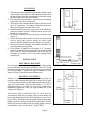
The coating selected to provide longer life to
the heat exchanger may smoke slightly upon
initial firing. Please provide adequate
ventilation if this ocurs.
WARNING: If the information in this manual is not followed
exactly, a fire or explosion may result causing property damage,
personal injury or loss of life.
•
•
•
•
-
Do not store or use gasoline or other flammable vapors and
liquids in the vicinity of this or any other appliance.
-
WHAT TO DO IF YOU SMELL GAS:
Do not try to light any appliance.
Do not touch any electrical switch; do not use any phone in your
building.
Immediately call your gas supplier from a neighbor’s phone.
Follow the gas supplier’s instructions.
If you cannot reach your gas supplier, call the fire department.
-
INSTALLATION AND SERVICE MUST BE PERFORMED
BY A QUALIFIED INSTALLER, SERVICE AGENCY OR
THE GAS SUPPLIER.
WARNING: Operation of this furnace without the properly installed, furnished vent system and vent cap
could result in Carbon Monoxide (CO) poisoning and possible death. For your safety, this furnace and the
vent system should be inspected at least annually by a qualified service person.
This unit is not approved for installation in greenhouses, or environments involving dusty, wet,
corrosive, or explosive conditions. Such conditions will invalidate the warranty and may create
unsafe conditions.
The appliance may be installed in an aftermarket permanently located, manufactured (mobile)
home, where not prohibited by local codes. This appliance is only for use with the type of gas
indicated on the rating plate. This appliance is not convertible for use with other gases, unless a
certified kit is used.
CONTENTS
Introduction……………………………….
Specifications and Dimensions……………
Safety Rules……………………………….
Clearances…………………………………
Location……………………………………
Installation…………………………………
Operation………………………………….
Lighting Instructions………………………
Pilot Adjustment…………………………..
2
2
3
4, 5
6
6
7
8, 9
10
Removing Burner……………………….
10
Proper Burner Flame……………………
10
Optional Side Discharge Kit……………
14
Terminal Block Wiring…………………
13
Manual Reset……………………………
13
Maintenance Instructions……………….
13
Trouble Shooting……………………….. 16,17
Parts Drawing…………………………...
18
Parts List………………………………... 19,20
Warranty…………………………………
22
INTRODUCTION
Read these installation and operating instructions carefully before you install or attempt to use this Direct
Vent Counterflow Wall Furnace. If you do not understand any part of the instructions, consult local authorities,
a qualified installer, service agency or the gas supplier. FAILURE TO READ OR UNDERSTAND THESE
INSTRUCTIONS CAN RESULT IN MALFUNCTION, INEFFICIENT OPERATION, PROPERTY
DAMAGE, SERIOUS INJURY OR DEATH.
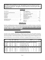
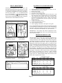
SPECIFICATIONS AND DIMENSIONS
Your Direct Vent Counterflow Wall Furnace is shipped in two cartons. One carton contains the furnace,
thermostat, thermostat wire and insulated staples. The second carton will have the vent tube, air intake tube
and vent cap assembly. After the furnace has been removed from the carton check the rating plate to verify
that the model number is correct and that the wall furnace is equipped with the type gas you intend to use.
Model
Number
Type
Type
Control Gas
Btu/Hr. Gas
Input Inlet
Finished Dimensions
Blower
Speed Amps
CFM
Approx.
Ship. Wt.
24 VOLT SYSTEM WITH LOW-BTU STANDING PILOT
DVCF403B-R
DVCF404B-R
DVCF653B-R
DVCF654B-R
24 Volt
24 Volt
24 Volt
24 Volt
Nat.
L.P.
Nat.
L.P.
40,000
40,000
62,500
62,500
½”
½”
½”
½”
14-5/16”Wx78-5/8”Hx11-3/4”D
14-5/16”Wx78-5/8”Hx11-3/4”D
14-5/16”Wx87-5/16”Hx11-3/4”D
14-5/16”Wx87-5/16”Hx11-3/4”D
1
1
2
2
1.95
1.95
3.05
3.05
320
320
440
440
128 Lbs.
128 Lbs.
142 Lbs.
142 Lbs.
24 VOLT SYSTEM WITH INTERMITTENT IGNITION (I.I.D.)
DVCF407B-R
DVCF408B-R
DVCF557B-R
DVCF558B-R
24 Volt
24 Volt
24 Volt
24 Volt
Nat.
L.P.
Nat.
L.P.
40,000
40,000
55,000
55,000
½”
½”
½”
½”
14-5/16”Wx78-5/8”Hx11-3/4”D
14-5/16”Wx78-5/8”Hx11-3/4”D
14-5/16”Wx87-5/16”Hx11-3/4”D
14-5/16”Wx87-5/16”Hx11-3/4”D
Page 2
1
1
2
2
2.2
2.25
3.3
3.35
320
320
440
440
130 Lbs.
130 Lbs.
144 Lbs.
144 Lbs.
SAFETY RULES
1. Follow all applicable local codes and ordinances. If there are none, follow the latest edition of the
National Fuel Gas Code, ANSI.Z223.1. A copy may be obtained from American Gas Association,
1515 Wilson Blvd., Arlington, Virginia 22209, or the National Fire Protection Association,
Batterymarch Park, Quincy, MA. 02269. In Canada, see the current CAN1-B149 installation code,
available from International Approval Services, 55 Scarsdale Road, Don Mills, Ontario, Canada
M3B-2R3.
2. The appliance, when installed, must be electrically grounded in accordance with local codes or, in
the absence of local codes, with the latest edition of National Electrical Code, ANSI/NFPA70. In
Canada, see the current CSA C22.2 Canadian Electrical Code, available from International Approval
Services, 178 Rexdale Boulevard, Etobicoke, Ontario, Canada M9W 1R3.
3. Do not install this furnace in a recreational vehicle or trailer.
4. Do not operate this furnace unless it is connected to the supplied vent system with vent cap in place.
Do not attempt to extend vent pipes. 12 inches is maximum length.
5. Never use a match, candle, flame or other source of ignition to check for gas leaks. Use only soapy
water or liquid detergent.
6. Before cleaning or servicing, turn off the gas and allow furnace to cool.
7. Do not operate furnace without grilles and front panel in place.
8. Due to high temperatures, locate furnace out of traffic and away from furniture and drapes.
9. Children and adults should be alerted to the hazard of high surface temperature and should be kept
away to avoid burns or clothing ignition.
10. Young children should be carefully supervised when they are in the same room with the furnace.
11. Do not place clothing or other flammable material on or near the furnace.
12. Installation and repair should be done by a qualified service person. The furnace should be inspected
before use and at least annually by a professional service person. More frequent cleaning may be
required due to excessive lint from carpeting, bedding material, etc. It is imperative that control
compartments, burners, and circulating air passageways of the furnace be kept clean.
13. Do not put anything around the furnace or vent cap that will obstruct the flow of combustion and
ventilation air.
14. When installing the furnace allow adequate accessibility clearances for servicing and proper operation.
(See Figure 1 – Page 5).
15. When the furnace is installed directly on carpeting, tile or other combustible material other than
wood flooring, the furnace shall be installed on a metal or wood panel extending the full width and
depth of the furnace.
16. Do not use this heater if any part has been under water. Immediately call a qualified service technician
to inspect the heater and to replace any part of the control system which has been under water.
17. For your safety, this furnace is equipped with a manual reset auxiliary limit switch. In case of failure
by the primary limit switch, this switch will shut the valve down completely before unsafe temperatures
are reached. After a cool down period, switch must be manually reset. If outages persist, call a
qualified service person.
18. Side discharge kit boots must not exceed 10 inches.
19. Locate the auxiliary limit switch and push in the red reset button. This will reset the switch in case
it accidentally opened during shipping.
Page 3
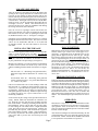
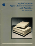
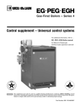
Vent Terminal
Air Supply Inlet
Area where terminal is not permitted
VENT TERMINAL CLEARANCES
REFERENCE LETTER TO
DRAWING
CANADIAN INSTALLAT
A = Clearance above grade, veranda,
porch, deck, or balcony
B = Clearance to window or door that
may be opened
12 Inches (30 cm)
C = Clearance to permanently closed
window
12 Inches (30 cm)
D = Vertical clearance to ventilated
soffit located above the terminal within
a horizontal distance of 2 Feet (61 cm)
from the center line of the terminal
E = Clearance to unventilated soffit
F = Clearance to outside corner
G = Clearance to inside corner
H = Clearance to each side of center
line extended above meter/ regulator
assembly
I = Clearance to service regulator vent
outlet
18 Inches (46 cm)
J = Clearance to nonmechanical air
supply inlet to building or the
combustion air inlet to any other
appliance
K = Clearance to a mechanical air
supply inlet
L = Clearance above paved sidewalk or
paved driveway located on public
property
M = Clearance under veranda, porch,
deck, or balcony
12 Inches (30 cm)
24 Inches (61 cm)
12 Inches (30 cm)
12 Inches (30 cm)
3 Feet (91 cm) within a height
15 Feet (4.5m) above the meter/
assembly
3 Feet (91 cm)
12 Inches (30 cm)
6 Feet (1.83 m)
7 Feet (2.13m) A vent shall not te
directly above a sidewalk or pav
driveway that is located betwee
single family dwellings and serve
dwellings.
12 Inches (30 cm) permitted only
veranda, porch, deck, or balcon
open on a minimum of two sides
¹ In accordance with the current CSA-B149.1 Natural Gas and Propa
Page 4
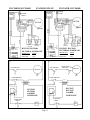
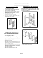
CLEARANCES
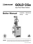
1. The minimum clearance to a side wall is 4”. (See Fig. 1). NOTE:
The unit may be recessed and rest directly against side studs and
the inside surface of the rear wall.
2. The minimum clearance to the ceiling is 4”. (See Figure 1).
3. The minimum clearance to the floor is 0”. (See Figure 1).
4. The minimum clearance from the side of the vent cap to any
protruding obstructions, or corners is 12”. (See Figure 2b).
5. The minimum clearance from any window to the side of the vent
cap is 9” for DVCF403, 404, 407 and 408 (See Figure 2), and
12” for DVCF557, 558, 653, and 654 (See Figure 2b).
6. The minimum clearance from any overhanging projection is 24”
to top of vent cap (See Figure 2).
7. RESIDENTIAL GARAGE INSTALLATION: Gas utilization
equipment in residential garages shall be installed so that all
burners and burner ignition devices are located not less than 18
inches (46 cm) above the floor. Such equipment shall be located,
or protected so it is not subject to damage by a moving vehicle.
Use care in selecting a good location within the garage. DO
NOT locate the appliance where heated air will be directed onto
a nearby parked vehicle. Paint may discolor or rubber may harden
and crack. DO NOT allow heated discharge air to blow directly
onto open or closed containers of paint, gasoline or other liquids
having flammable vapors.
Ceiling
4” Minimum
SIDE WALL
4” Minimum
FLOOR 0”
FIGURE 1
24” Min.
24” Min.
12”
Min.
12”
Min.
9”
Min.
12”
Min.
12” Min.
12” Min.
FIGURE 2B / DVCF557B, 558B, 653B, AND 654B
FIGURE 2 / DVCF403B, 404B, 407B, AND 408B
Page 5
LOCATIONS
1. This furnace must be installed on an outside wall and vented
to the outside. If possible, this wall should be on the side of
the house that receives the least amount of wind since strong
gusting winds could cause pilot outage.
2. For most efficient performance, locate furnace as centrally
as possible in the area to be heated.
3. The furnace can be installed flush against a wall or recessed
up to 10” maximum. For proper combustion, make sure
unit is level front to back and side-to-side.
4. Do not install the furnace in a closet, alcove or small hallway
where the furnace could be isolated from the space to be
heated by closing a door.
5. Be sure the vent cap will have the proper clearances (See
Figure 2).
6. Check inside the wall to make sure there are no obstacles
such as water pipes, electric wiring, etc. which could
interfere with the installation of the furnace or vent tubes.
7. Be sure to maintain adequate accessibility clearances for
servicing and proper operation.
8. If the furnace is installed in a basement, a 12” clearance
must be maintained between ground level and the bottom
of the vent cap. Do not install furnace where vent cap will
terminate in a window well or any other opening below
ground level.
INSTALLATION
ELECTRICAL ROUGH-IN
For convenience, this furnace is equipped with a three-prong
power cord located on the top left of heater. The 115V wiring
should be brought in on the left side terminating in a receptacle
box (not provided). Consult local codes or ordinances. (For
Amps, see Page 2/Specifications and Dimensions).
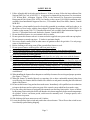
ROUGH-IN GAS SUPPLY
Install a 1/2 inch diameter gas supply line. The gas line can
enter the cabinet through the right side or bottom (See Figure
3). The gas line must have an individual manual shut off valve.
Also, you must install a drip leg and provide a 1/8” N.P.T.
plugged tapping, accessible for test gauge connection,
immediately upstream of the gas supply connection to the
furnace (See Figure 4).
3-1/2”
2-5/8”
1-1/2 OA
FIGURE 3
Gas
Supply
Line
Drip
Leg
1/8 N.P.T.
Pressure Tap
FIGURE 4
9-1/4
DIA.
WALL
STUDS
The furnace and its individual shut off valve must be
disconnected from the gas supply piping system during any
pressure testing of that system at test pressures in excess of ½
psig (3.5kPa). The furnace must be isolated from the gas supply
piping system by closing its individual manual shut off valve
during any pressure testing of the gas supply piping system at
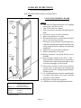
FIGURE 5
test pressures equal to or less than ½ psig (3.5kPa).
Page 6
Manual
Cut Off
Valve
DVCF40 - 59”
DVCF55/65 - 68-1/2”
FINISHED
FLOOR
LOCATE VENT OPENING
After the location of the heater has been determined, the
opening for the vent pipe should be cut. If the heater is to be
recessed, cut out opening for heater between studs on the
interior wall and cut out the floor plate between the studs, so
heater will set flat on floor as all dimensions are given from
a finished floor. The height of the cut out for a 40,000 BTU
model is 78-5/8”, for the 55,000 and 62,500 models the cut
out height is 87-5/16”. NOTE: This dimension may be
increased to allow more room for installation and making
the wiring connection, then refinished.
Next, cut out a 9-1/4” opening in exterior wall for the vent
tubes to pass through. The center of opening for the 40,000
BTU furnace is 59”, the center for opening for 55,000 and
62,500 BTU furnaces is 68-1/2”. See Figure 5, on Page 6.
If the heater is to be surfaced mounted, cut out 9-1/4” opening
through the interior and exterior wall. The center of cut out
will be 59” for 40,000 BTU and 68-1/2” for 55,000 and
62,500 BTU models. Be sure both cutouts are level with
each other.
Vent
Cap
Vent Cap
Spacer
Plate
Heat
Exchanger
Collar
FIGURE 6
INSTALLING THE FURNACE
The vent system supplied with this furnace will accommodate
walls ¾” (when recessed) up to 12” thick. Use only the
exhaust tube, air intake tube and vent cap supplied with
heater. Do not attempt to lengthen the exhaust or air intake
tubes, this could cause an imbalance in the heater resulting
in poor performance and pilot outage (See Figure 6).
Measure exact distance “X” between surface on which back
of cabinet will rest (inside of recessed cavity or face of wall
when freestanding) and the outside wall surface (see Figure
6).
Inlet Air Tube “A” – Measuring from gasketed surface,
mark and cut pipe same as dimension “X”. Remove any
burrs.
Vent Exhaust Tube “B” – Measuring from gasketed
surface, mark and cut pipe 1-3/4” greater than dimension
“X”. Remove any burrs.
Fasten vent exhaust tube “B” to heat exchanger collar and
Inlet Air Tube “A” to flange on back of furnace using 16 #
3/8 screws (“C”) provided. Be sure gaskets are in place and
not damaged. Anytime the vent pipes are removed check
and replace gaskets (if necessary). Failure to replace missing
or damaged gaskets may expose homeowner to life
threatening conditions.
Secure furnace in place using 2 holes provided in bottom of
casing. NOTE: Make sure both tubes are centered in cut
out. Slide the vent cap onto the pipes extending from the
back of the furnace. A rotating or twisting motion will ease
this installation. Secure vent cap and vent cap spacer plate
to wall causing the vent tubes to have a slight downward
pitch. This will prevent water from entering. Anchors (not
provided) may be required. Caulk around vent cap spacer
plate with caulking provided. NOTE: Some framing may
be necessary to provide a flat surface against the vent cap
spacer plate and to prevent rain from entering the wall
opening.
Page 7
GAS CONNECTION
Make the gas connection between the manual shut off valve
and the furnace gas control valve with approved ½”
connectors. Compounds used on threaded joints of gas
piping shall be approved for use with L.P. gas. The gas
lines must be checked for leaks by the installer with soapy
water or liquid detergent, never use an open flame. If
connections are not exposed, a pressure test must be run.
Be sure to disconnect the gas supply line from the appliance
valve before pressure testing. The manifold pressure is
pre-set at the factory and should be 3.5” w.c. for Natural
Gas and 10” w.c. for L.P. Gas. The minimum inlet pressure
for Natural Gas is 4.5” w.c. and 11” w.c. for L.P. Gas, “for
purpose of input adjustment”. The maximum inlet pressure
should never exceed 7.0” w.c. on Natural Gas or 14” w.c.
on L.P. Gas.
THERMOSTAT INSTALLATION
Follow the instructions included with the thermostat. Select
a location for the thermostat on an inside wall approximately
5 feet above the floor where it won’t be affected by heat or
cold sources such as direct sunlight, televisions, fireplaces,
hidden hot or cold water pipes, drafts, etc., and a minimum
of 4’ from the heater. The thermostat must never be placed
in an adjacent room. Connect thermostat wires to
thermostat and mount to wall. Run wire to furnace and
make connections to thermostat wires coming out of top of
furnace. Use insulated staples (provided) to secure wire to
wall.
OPERATION
This unit uses a “step action” valve. When the heater comes
on initially, it operates at a lower pressure to insure proper,
quiet, ignition. After 20 seconds or less, it automatically
steps up to the proper manifold pressure with a discernable
increase in flame height.
After the heat exchanger has warmed sufficiently, the fan
will automatically come on to efficiently transfer the heat
into the room. NOTE: All but the 40,000 BTU unit (which
is one-speed) have an automatic two-speed fan.
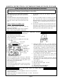
LIGHTING INSTRUCTIONS: DVCF403B, DVCF404B, DVCF653B, DVCF654B
FOR YOUR SAFETY READ BEFORE LIGHTING
WARNING: If you do not follow these instructions exactly, a fire or explosion may result
causing property damage, personal injury or loss of life.
•
A. This appliance has a pilot which must be lighted by
hand. When lighting the pilot, follow these instructions exactly.
B. BEFORE LIGHTING, smell all around the appliance
area for gas. Be sure to smell next to the floor because
some gas is heavier than air and will settle on the
floor.
•
•
•
If you cannot reach your gas supplier, call the fire
department.
C. Use only your hand to push in or slide the gas control
lever. Never use tools. If the lever will not push in or
slide by hand, don’t try to repair it, call a qualified service
technician. Force or attempted repair may result in a fire
or explosion.
D. Do not use this appliance if any part has been under water.
Immediately call a qualified service technician to inspect
the appliance and to replace any part of the control system
and any gas control which has been under water.
WHAT TO DO IF YOU SMELL GAS:
Do not try to light any appliance.
Do not touch any electric switch, do not use any
phone in your building.
Immediately call your gas supplier from a neighbor’s
phone. Follow the gas supplier’s instructions.
LIGHTING INSTRUCTIONS
STOP! Read the information on the safety label.
Set thermostat to lowest setting.
Turn off all electric power to the appliance.
Remove cabinet door.
Push in gas control lever slightly and slide right
$to “OFF”.
Max. (High)
Gas Control
Pressure Regulator
Lever
9.
NOTE: Knob
can not be
moved to
“OFF” unless it
is pushed in
slightly. Do
not force.
Outlet (Manifold)
Pressure Tap
1.
2.
3.
4.
5.
•
Step Pressure Regulator
6.
7.
8.
Wait five (5) minutes to clear out any gas. Then smell
for gas, including near the floor. If you smell gas, STOP!
Follow “B” in the information on the safety label. If you
don’t smell gas, go to the next step.
Open sight glass cover.
Locate red piezo ignitor button on side of gas control.
Locate pilot behind sight glass. (Follow metal pilot tube
from gas control).
•
10.
11.
12.
13.
14.
Slide gas control lever left % to “Set” and hold.
Immediately begin a series of pushing and releasing the
red piezo ignitor button, while observing the pilot through
the sight glass. Continue to spark until pilot is lit.
Continue to hold the gas control lever to “Set” for about
one (1) minute after the pilot is lit. Release the gas control
lever and it will return to “Pilot”. Pilot should remain
lit. If pilot goes out, repeat steps 5 thru 9.
If gas control lever does not return to “Pilot” when
released, STOP and immediately call your service
technician or gas supplier.
If the pilot will not stay lit after several tries, slide the
gas control lever to “OFF” and call your service technician
or gas supplier.
Close sight glass cover.
Slide gas control lever right $ to “ON”.
Replace cabinet.
Turn on all electric to the appliance.
Set thermostat to desired setting.
TO TURN OFF GAS TO APPLIANCE
1.
2.
3.
4.
5.
Turn thermostat to it’s lowest setting.
Turn off all electric power to the appliance if service is to be performed.
Remove cabinet door.
Push in gas control lever slightly and slide right $ to “OFF”. Do not force.
Replace cabinet door.
Page 8
LIGHTING INSTRUCTIONS: DVCF407B, DVCF408B, DVCF557B, DVCF558B
FOR YOUR SAFETY READ BEFORE LIGHTING
WARNING: If you do not follow these instructions exactly, a fire or explosion may result causing
property damage, personal injury or loss of life.
A. This appliance is equipped with an ignition device which
automatically lights the pilot. Do not try to light the
pilot by hand.
B. BEFORE LIGHTING, smell all around the appliance area
for gas. Be sure to smell next to the floor because some
gas is heavier than air and will setting on the floor.
WHAT TO DO IF YOU SMELL GAS:
Do not try to light any appliance.
Do not touch any electric switch; do not use any phone
in your building.
Immediately call your gas supplier from a neighbor’s
phone. Follow the gas supplier’s instructions.
•
•
•
•
If you cannot reach your gas supplier, call the fire
department.
C. Use only your hand to push in or slide the gas control
lever. Never use tools. If the lever will not push in or
slide by hand, don’t try to repair it, call a qualified
service technician. Force or attempted repair may result
in a fire or explosion.
D. Do not use this appliance if any part has been under
water. Immediately call a qualified service technician
to inspect the appliance and to replace any part of the
control system and any gas control which has been
under water.
LIGHTING INSTRUCTIONS
STOP! Read the information on the safety label.
Set the thermostat to it’s lowest setting.
Turn off all electric power to the appliance.
This appliance is equipped with an ignition device which
automatically lights the pilot. Do not try to light the
pilot by hand.
5. Remove cabinet door.
6. Push in gas control lever slightly and slide right $ to
“OFF”.
Maximum (High)
Pressure Regulator
Gas Control
Lever
8.
Outlet (Manifold)
Pressure Tap
NOTE: Lever
can not be
moved to
“OFF” unless
it is pushed
in slightly. Do
not force.
Step Pressure Regulator
7.
Wait five (5) minutes to clear out any gas. Then small
for gas, including near the floor. If you smell gas, STOP!
Follow “B” in the information on the safety label. If you
don’t smell gas, go to the next step.
Slide gas control lever left % to “ON”.
Maximum (High)
Pressure Regulator
Step Pressure Regulator
9.
10.
11.
12.
Replace cabinet door.
Turn on all electric power to the appliance.
Set thermostat to desired setting.
If the appliance will not operate, follow the
instructions “TO TURN OFF GAS TO
APPLIANCE” and call your service technician or
gas supplier.
TO TURN OFF GAS TO APPLIANCE
1.
2.
3.
4.
5.
Turn thermostat to it’s lowest setting.
Turn off all electric power to the appliance if service is to be performed.
Remove cabinet door.
Push in gas control lever slightly and slide $ to “OFF”. Do not force.
Replace cabinet door.
Page 9
Gas Control
Lever
Outlet (Manifold)
Pressure Tap
1.
2.
3.
4.
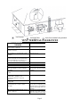
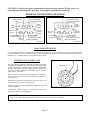
TO REMOVE MAIN BURNER FOR
PILOT ADJUSTMENT
INSPECTION AND CLEANING
Locate the pilot adjustment screw on the valve. The
pilot flame should surround at least the top 3/8” of the
powerpile (pilot generator) or flame sensor (see Figure
7). The pilot is unregulated so it will be operating at
inlet line pressure (Max. 7” w.c. for Natural Gas and
11” w.c. for Propane). To decrease the pilot flame,
turn the screw clockwise
(approximately six full
turns to bottom of pilot light channel) until you produce
sufficient flame at the minimum noise level.
PILOT FLAME ADJUSTMENT: Pilot flame
should envelop 3/8 to 1/2 inch of the tip of sensor.
3/8”
to
1/2”
3/8” to 1/2”
1.
2.
3.
4.
5.
6.
Turn thermostat to lowest setting and allow furnace to cool.
Turn off all electric power to furnace.
Remove lower grille.
Disconnect gas supply to valve.
Disconnect wires from gas valve.
Remove 15 screws holding burner door to burner box. Pull
door forward to remove complete burner, gas valve assembly.
7. After inspecting and cleaning, place burner assembly back
into burner box and tighten 15 screws. NOTE: Be sure door
gasket is not damaged and will effect a proper seal or pilot
outage will occur.
8. Connect wires back to valve.
9. Connect gas supply back to valve.
10. Turn on electric to furnace.
11. Follow lighting instructions, and replace lower grille.
It is recommended that the furnace and all components be inspected
at least annually by a qualified service person. This should include
the burner, pilot, heat exchanger, and vent system. Be sure that
the flow of combustion and ventilation air is not obstructed.
IMPORTANT: Keep burner and control compartment clean.
Vacuum control compartment at the start of the heating season
and as often as needed.
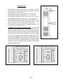
PROPER BURNER FLAME
FIGURE 7A
STANDING PILOT
Pilot Adj. Screw
ROBERTSHAW
7200ER-SO4
FIGURE 7C
STANDING PILOT
1-1/
3/4
2
FIGURE 7B
I.I.D. PILOT
Pilot Adj. Screw
ROBERTSHAW
7200IPER-SO4
FIGURE 7D
I.I.D. PILOT
The burner flame may be observed by raising the sight glass cover.
A proper flame will have a dark blue inner mantle that sits right
on top of the burners with a lighter blue outer mantle rising above
the burner (See Figure 8). There may be some yellow where the
pilot flame and burner flame meet. There is no primary air
adjustment on the burner, and proper flame is assured since the
correct manifold pressure and orificing has been done at the factory.
NOTE: It is advised that the burner flames be checked at least
twice during the heating season for any changes in burner flame
characteristics. The appliance area must be kept clear and free
from combustible materials, gasoline, and other flammable vapors
and liquids. This heater comes from the factory with the proper
burner orifice for elevations up to 2,000 feet. Heaters installed
above 2,000 feet must be derated 4% for every 1,000 feet. For the
proper orifice size, find the Model Number and elevation on the
orifice chart. Replace burner orifice.
NATURAL GAS
MODEL
0 to
2,000 4,000 6,000 8,000 –
NUMBER
2,000’ 4,000’
6,000’
8,000’
10,000’
DVCF403B 32
34
35
36
40
DVCF407B 32
34
35
36
40
DVCF557B 3.6m 29
30
30
31
DVCF653B 25
27
28
29
30
ORDER KIT #49840 2287-1 HIGH ALTITUDE KIT
L.P. GAS
FIGURE 8
MODEL
0 to
2,000 4,000 6,000 8,000 –
NUMBER
2,000’ 4,000’
6,000’
8,000’
10,000’
DVCF404B 49
50
51
52
52
DVCF408B 49
50
51
52
52
DVCF558B 44
45
47
48
49
DVCF654B 2.3mm 44
45
47
48
ORDER KIT #49840 2287-1 HIGH ALTITUDE KIT
Page 10
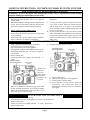
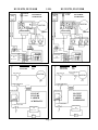
STANDING PILOT
DVCF653B, DVCF654B
THERMOSTAT
THERMOSTAT
POWER
CORD
MOTOR
BROWN
BLACK
TRANSFORMER
GREEN
BLACK
BROWN
AUXILIARY
LIMIT
SWITCH
FAN
SWITCH
DVCF403, DVCF404
PICTORIAL SCHEMATIC
MODEL NO.
DVCF403
DVCF404
GAS VALVE
BLACK
BLACK
LIMIT
SWITCH
BLACK
BLACK
BLUE
WHITE
RED
BLACK
BLACK
RED
BLUE
GREEN
WHITE
MOTOR
BROWN
BLACK
TRANSFORMER
BLACK
BLACK
GREEN
WHITE
WHITE
BLACK
BLACK
BLACK
BLACK
WHITE
GREEN
WHITE
POWER
CORD
BLACK
DVCF403B, DVCF404B
AUXILIARY
LIMIT
SWITCH
GAS VALVE
AMPS
1.95
1.95
FAN SWITCH
LIMIT
SWITCH
FAN
SWITCH
DVCF653, DVCF654
PICTORIAL SCHEMATIC
MODEL NO.
DVCF653
DVCF654
SELECTOR
SWITCH
FAN SWITCH
MOTOR
AMPS
3.05
3.05
MOTOR
LIMIT SWITCH
LIMIT SWITCH
115 V.A.C.
115 V.A.C.
TRANSFORMER
TRANSFORMER
THERMOSTAT
SELECTOR
SW. BLACK
24 V.A.C.
THERMOSTAT
24 V.A.C.
DVCF653
DVCF654
LADDER
SCHEMATIC
DVCF403
DVCF404
LADDER
SCHEMATIC
AUXILIARY
LIMIT
AUXILIARY
LIMIT
GAS
VALVE
GAS
VALVE
Page 11
DVCF407B, DVCF408B
THERMOSTAT
I.I.D.
DVCF407, DVCF408
PICTORIAL
SCHEMATIC
POWER
CORD
DVCF557B, DVCF558B
THERMOSTAT
DVCF557, DVCF558
PICTORIAL
SCHEMATIC
POWER
CORD
BLACK
LIMIT SWITCH
BLACK
MOTOR
TRANSFORMER
FAN
SWITCH
AUXILIARY
LIMIT
SWITCH
PILOT
GREEN
LIMIT SWITCH
Selector
Sw. Black
FAN
SWITCH
PILOT
BLACK
TH
PV
SP715-NAT. SENSE
OR
MV
SP735-L.P. MV/PV
TR
IGN
GAS VALVE
P
C
M
MODEL NO.
DVCF407
DVCF408
SP715-NAT.
OR
SP735-L.P.
AMPS
2.2
2.25
FAN SWITCH
TH
PV
SENSE
MV
MV/PV
TR
IGN
GAS VALVE
P
C
M
MODEL NO.
DVCF557
DVCF558
FAN SWITCH
MOTOR
AMPS
3.3
3.35
SELECTOR
SWITCH
MOTOR
LIMIT SWITCH
LIMIT SWITCH
THERMOSTAT
WHITE
RED
BLACK
BLACK
BLUE
GREEN
RED
BROWN
BLACK
BLACK
BLACK
BLACK
BLUE
WHITE
BLACK
MOTOR
BROWN
BLACK
TRANSFORMER
AUXILIARY
LIMIT
SWITCH
GREEN
WHITE
BLACK
BLACK
BLACK
BLACK
WHITE
GREEN
WHITE
WHITE
115 V.A.C.
115 V.A.C.
TRANSFORMER
TRANSFORMER
24 V.A.C.
THERMOSTAT
24 V.A.C.
DVCF557
DVCF558
LADDER
SCHEMATIC
DVCF407
DVCF408
LADDER
SCHEMATIC
AUXILIARY LIMIT
AUXILIARY LIMIT
SP715 - NAT.
OR
SP735 - L.P.
SP715 - NAT.
OR
SP735 - L.P.
GAS
VALVE
GAS
VALVE
Page 12
CAUTION: Label all wires prior to disconnection when servicing controls. Wiring errors can
cause improper and dangerous operation. Verify proper operation after servicing.
TERMINAL BLOCK WIRING DIAGRAM
Selector Switch
(Red)
Motor
(Red)
Fan/Limit Switch (Brown)
Power Cord (Black)
Transformer (Black)
Fan/Limit Switch (Brown)
Power Cord (Black)
Transformer (Black)
Limit
Switch
(Blue)
Limit
Switch
(Blue)
MOTOR (White)
Power Cord
(Green)
Terminal Board
Ground (Green)
Motor
(Green)
MOTOR (White)
Selector
Switch
(Black)
Fan
Switch
(Black)
Power Cord
(Green)
Motor (Black)
Transformer (Black)
Power Cord (White)
P/N 91123
DVCF557B, 558B, 653B, 654B
Terminal Board
Ground (Green)
Motor
(Green)
Motor (Black)
Transformer (Black)
Power Cord (White)
P/N 91122
DVCF403B, 404B, 407B, 408B
MANUAL RESET SWITCH
For your safety this furnace is equipped with a manual reset limit switch. In case of failure by the primary limit switch, this
switch will shut the valve down completely before unsafe temperatures are reached. After a cool down period, switch must be
manually reset. If outages persist, call a qualified service person.
MAINTENANCE INSTRUCTION
For proper and safe operation, keep furnace and furnace area clean.
At regular intervals turn control valve off, let cool and clean inside
control compartment. To clean cabinet, use only a damp cloth.
Do not use any kind of solvent or cleaning fluid that could leave a
residue or invisible coating that would burn or give off fumes
when furnace is turned on.
OIL TUBE
Have the furnace checked, cleaned, and repaired by a qualified
service person for vent system, pilot and burner operation prior
to use each year.
The bearings of the fan motor should be oiled every twelve (12)
months with S.A.E. 20 oil. (See Figure 10).
Follow a regular service and maintenance schedule for safe and
efficient operation.
FIGURE 10
Examine the venting system as a routine part of the safety
performance check on an annual basis.
WARNING: This is a gas-fired appliance. Keep the area clear of gasoline and other flammaable vapors and
liquids. All combustible material must be kept clear of this area to avoid fire or explosion.
Page 13
OPTIONAL SIDE DISCHARGE KITS
ROUGH-INS FOR SIDE DISCHARGE
SIDE DISCHARGE ON CASING
1.
2.
3.
4.
5.
6.
7.
8.
Use Optional Kit No. 306SR-A.
Cut out and remove embossed area on casing side.
Remove knockout from inner liner.
Place 1-1/2” boot from kit through opening,
matching flanges of boot to knockout on inner liner.
Mark screw holes and remove boot.
Drill holes with a 1/8” drill.
Attach inner boot with screws provided.
Place grille into position, drill holes into casing,
and attach with screws provided.
Install plaster grounds as shown in Figure 9. NOTE: When
side discharge Kit No. 30SRB is being used, furnace should be
set exactly 4” from side wall.
Plaster
Ground
14-3/8”
1 0 -3 /
16”
SIDE
FIGURE 9
KIT NO. 306SR
SIDE REGISTER - FLUSH
SIDE DISCHARGE (With Extension Boot)
NOTE: Maximum boot length is 10 inches.
1.
2.
3.
4.
5.
6.
7.
8.
9.
Use Optional Kit No. 30SRB-A.
Cut opening in drywall as shown in Fig. 9.
Position plaster ground as shown in Figure 9.
(Optional).
Cut out and remove embossed section on casing side.
Remove knockout on inner liner.
Put heater into position.
Place inner boot into position, mark and cut boot
flush with wall. Place outer boot into position, mark
and cut boot flush with wall.
Place boot trim into position, slide inner boot through
wall from adjacent room and attach to inner liner.
Slide outer boot through wall from adjacent room
and attach to casing side.
Place grill in position and secure to wall.
KIT NO. 30SRB
SIDE REGISTER W/BOOT
Page 14
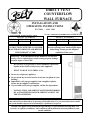
14-PEK KIT INSTRUCTIONS
(14’ PLUG EXTENSION KIT)
FOR NON-RECESSED INSTALLATIONS ONLY
UNITS WITH TERMINAL BOARD
90 Degree
Outside
Corner
1
3 FT.
SECTION
2
L
AL
W
3 FT.
SECTION
3
BOTTOM
SECTION
4
STEP #
1. Turn heater off following Section 3 in “Lighting
Instructions” and allow to cool.
2. Turn off all electricity to heater.
3. Remove top louver assembly, fan shroud and fan
blade.
4. Loosen two screws on romex connector.
5. Remove junction box cover plate.
6. Disconnect three power cord terminals and pull
power cord out of top of heater.
7. Insert power cord provided in kit through romex
connector and plug onto terminal board following
wiring diagram found in lighting and operating
instructions.
8. Tighten two screws on romex connector.
9. Replace junction box cover plate.
10. Replace fan blade, fan shroud and top louver
assembly.
11. Snap 90 degree outside corner (Ref. 1) onto 3
foot section (Ref. 2) plastic raceway. Insert power
cord and remove blue backing from adhesive strip
on raceway and apply to side of heater.
12. Insert power cord into second 3-foot section of
raceway (Ref. 3) and remove blue backing and
apply to side of heater, butting up against bottom
of other section.
13. Cut 14-inch long bottom section to required length
(see chart), insert power cord, remove backing
and apply to side of heater.
14. Plug power cord into wall receptacle.
15. Light the heater following lighting instructions.
LENGTH OF BOTTOM
SECTION (REF. 4)
MODEL NO.
PLASTIC RACEWAY
DVCF40
5-5/16 Inches
DVCF55
14 Inches
DVCF65
14 Inches
NOTE: Above lengths terminate approximately
2 inches above floor.
Page 15
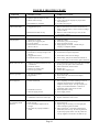
TROUBLE SHOOTING CHART
SYMPTOM
Flame too large
POSSIBLE CAUSES
CORRECTIVE ACTION
1. Defective operator section of valve.
2. Burner orifice too large.
3. If installed above 2,000 feet.
Yellow burner flame
1. Clogged burner ports.
1. Replace valve.
2. Check with local gas company for proper orifice
size and replace.
3. See orifice chart, page 10.
Gas Odor
1. Gas leak.
1. Remove main burner and check for obstructions in
throat, ports, and orifices. Clean - but do not enlarge
ports or orifices.
2. Make sure area around vent cap is clear, be sure
vent system is sealed.
1. See Page 1.
Delayed Ignition
1.
2.
3.
4.
1.
2.
3.
4.
2. Obstructions around vent cap.
Failure to ignite
Pilot flame too small.
Burner ports clogged at pilot.
Low gas pressure.
Pilot decreases in size when main
burners come on.
1. Main gas off.
2. Thermostat not set high enough to call
for heat.
3. Clogged burner orifice.
4. Thermostat wired wrong or defective.
Adjust pilot flame.
Clean burner ports (do not enlarge).
Check gas supply pressure.
Supply piping is too small. Consult local gas
company or competent installer.
1. Open all manual gas valves.
2. Set thermostat to higher temperature.
3. Clean burner orifice (do not enlarge).
4. Check wiring, jump across thermostat terminals at
valve, if valve open, re-check wires, replace thermostat.
Burner won’t turn off
1. Defective or damaged thermostat wire,
or thermostat.
2. Thermostat location.
3. Defective or sticking valve.
4. Excessive gas pressure.
1. Can be checked by removing wire from valve terminal.
If valve goes off, replace wire or thermostat.
2. Follow instructions, check location.
3. Replace valve.
4. Contact utility supplying gas.
Incorrect gas input
1. Gas input not checked.
2. Clogged orifice.
1. Re-check gas input.
2. Clean orifice with a smooth wood toothpick,
do not enlarge.
Not enough heat
1. Furnace undersized.
2. Thermostat set too low.
3. Incorrect supply pressure.
1. This is especially true when a dwelling or room is
enlarged. Have the heat loss calculated and
compare to furnace output. Your gas company can
supply you with this information. If furnace is
undersized, replace with correct size unit.
2. Raise temperature setting.
3. Check supply pressure.
Too much heat
1. Thermostat set too high.
2. Combination control valve stuck open.
1. Lower temperature setting.
2. Replace combination control valve.
Pilot and main burner
go out during normal
operation
1. Weak thermocouple.
2. Input too high.
3. Cover around pilot lighter hole not
air tight.
4. Vent tubes not properly installed or
sealed.
1. Check millivoltage and replace if low.
2. Check input rate.
3. Tighten wing nuts securing cover and sight glass.
Check and replace gasket if needed.
4. Follow instructions. Check both exhaust and air
intake tubes, and vent cap. Be sure all gaskets are
in place and properly sealed. Use only tubes and
vent cap supplied. Do not alter vent tubes or cap.
Page 16
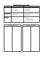
TROUBLE SHOOTING CHART - Continued
SYMPTOM
POSSIBLE CAUSES
CORRECTIVE ACTION
Burner won’t turn on
1.
2.
3.
4.
5.
6.
Gas valve not turned on.
No voltage to valve.
Defective thermostat.
No 115 V. Line voltage.
Gas valve defective.
Manual reset switch not engaged.
1.
2.
3.
4.
5.
6.
Turn gas valve to “on” position.
Check for 24 Volts to valve from transformer.
Check wall thermostat.
Provide line voltage.
Replace gas valve.
Depress red button on switch.
(STANDING PILOT)
Pilot won’t light, or
stay lit
1.
2.
3.
4.
Air in line.
Defective thermocouple
Pilot flame too low.
Manual reset switch not engaged.
1.
2.
3.
4.
Bleed line.
Replace thermocouple.
Adjust pilot flame.
Depress red button on switch.
(I.I.D. PILOT)
1. Sparker won’t work.
Pilot won’t light
2. Sparker won’t light pilot.
3. Manual reset switch not engaged.
SERVICE RECORD
1. Check wire connections, provide adequate
ground.
2. {a} Pilot flame too small.
{b} Turn valve to “on” position.
{c} Check for pilot restriction.
3. Depress red button on switch.
SERVICE RECORD
Page 17
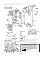
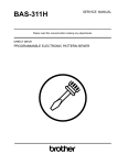
DIRECT VENT COUNTERFLOW WALL FURNACE
MODELS:
DVCF403B-R, DVCF404B-R
DVCF407B-R, DVCF408B-R
DVCF557B-R, DVCF558B-R
DVCF653B-R, DVCF654B-R
1d
24
35
16
3
17 11
1e
1b
18
2
36
1f
61
1a
50
4
52 38
30
7
8
1c
19
9
21 20
51
22
44
26
39
10
1g
6
VENT ASSEMLBY
23
40 37
43
55
14
28b
12 25b
28 25
34
33
58
13
32
60
57 53
59 31 56 41
13b
49
48 47
46
Prices and specifications subject
to change without notice.
All prices are F.O.B. factory.
BURNER ASSEMBLY
DVCF40B-R, DVCF55B-R, DVCF65B-R SERIES
54
15
45
THERMOSTAT
SPARK IGNITER I.I.D.
Mr. Contractor, we only sell parts through our
wholesalers, but the prices listed are for your
convenience. For prompt parts service, contact the
wholesaler from which you purchased your Cozy
heater. NOTE: Parts & schematic drawings on
current models are shown at
www.cozyheaters.com.
Page 18
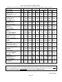
HOW TO PROPERLY ORDER PARTS
In addition to part description and part number, please give model number, serial number, and type of gas used.
MODEL NUMBER
PART DESCRIPTION
Casing Side, Right
Casing Side, Left
Center Front Panel Assembly
Top Assembly
Upper Back Assembly
Lower Back Assembly
Bottom Assembly
Casing Mounting Brackets
Liner Assembly
Fan Shroud Assembly
Top Louver
Bottom Louver Assembly
Upper Front Shield
Switch Box
Switch Box Cover
Lower Front Shield
Motor Mounting Bracket
Burner
Pilot Bracket
Valve, 7200ER, Natural Gas
Valve, 7200ER, L.P. Gas
Valve, 7200IPER, Natural Gas
Valve, 7200IPER, L.P. Gas
Manifold
Burner Orifice, Natural Gas
Burner Orifice, L.P. Gas
Fan Motor
Fan Blade
Rubber Grommet
Limit Switch 60T11-L220F
Limit Switch 60T11-L180F
Fan Switch 60T12-120-15 Deg. F
Speed Switch 60T13-F160-30
Aux. Limit Switch 60T15-L350
Thermostat 24 Volt
Transformer
Transformer Plate
Terminal Board
Pilot 0.140.512, Natural Gas
Pilot 0.140.502, L.P. Gas
Cozy Handle
Thermostat Wire
Thermocouple Q309A1954
Insulated Staples
Pilot 3S-24F, Natural Gas
Pilot 3S-24F, L.P. Gas
Wiring Harness
Flame Sensor S-1
NAT.
DVCF403B-R
DVCF407B-R
DVCF557B-R
DVCF653B-R
L.P.
DVCF404B-R
DVCF408B-R
DVCF558B-R
DVCF654B-R
REF.
PART
LIST
PART
LIST
PART
LIST
PART
LIST
NO.
NO.
PRICE
NO.
PRICE
NO.
PRICE
NO.
PRICE
1a
34065
$56.10
34065
$56.10
34560
$61.30
34560
$61.30
1b
34055
$56.10
34055
$56.10
34550
$61.30
34550
$61.30
1c
34104
$27.80
34104
$27.80
30534
$28.80
30534
$28.80
1d
34050
$10.60
34050
$10.60
34050
$10.60
34050
$10.60
1e
34080
$42.80
34080
$42.80
34080
$42.80
34080
$42.80
1f
34090
$36.60
34090
$36.60
34575
$40.40
34575
$40.40
1g
34070
$16.10
34070
$16.10
34070
$16.10
34070
$16.10
N/A *30260
$1.20 *30260
$1.20 *30260
$1.20 *30260
$1.20
2
34115
$81.30
34115
$81.30
34600
$87.60
34600
$87.60
3
34140
$23.80
34140
$23.80
34140
$23.80
34140
$23.80
4
34100
$16.30
34100
$16.30
34590
$17.70
34590
$17.70
6
30100
$31.60
30100
$31.60
30100
$31.60
30100
$31.60
7
30250
$3.50
30250
$3.50
30250
$3.50
30250
$3.50
8
30252
$7.10
30252
$7.10
30450
$7.20
30450
$7.20
9
30253
$2.80
30253
$2.80
30253
$2.80
30253
$2.80
10
30256
$5.10
30256
$5.10
30256
$5.10
30256
$5.10
11 *34088
$3.60 *34088
$3.60 *34579
$2.10 *34579
$2.10
12
72107
$38.20
72107
$38.20
72107
$38.20
72107
$38.20
53
34440
$4.00
34440
$4.00
34440
$4.00
34440
$4.00
13
72090
$137.90
N/A
N/A
N/A
N/A
72090
$137.90
13
72091
$137.90
N/A
N/A
N/A
N/A
72091
$137.90
13b
N/A
N/A
72092
$129.00
72092
$129.00
N/A
N/A
13b
N/A
N/A
72093
$129.00
72093
$129.00
N/A
N/A
14
72103
$19.10
72103
$19.10
72103
$19.10
72103
$19.10
15
72147
$3.40
72147
$3.40
72140
$3.40
72142
$3.40
15
72149
$3.40
72149
$3.40
72141
$3.40
72143
$3.40
16
72108
$73.90
72108
$73.90
72110
$83.90
72110
$83.90
17
78101
$24.20
78101
$24.20
78101
$24.20
78101
$24.20
18
78010
$3.00
78010
$3.00
78010
$3.00
78010
$3.00
19
N/A
N/A
N/A
N/A
72160
$5.90
72160
$5.90
19
78065
$5.90
78065
$5.90
N/A
N/A
N/A
N/A
20
78067
$6.10
78067
$6.10
78067
$6.10
78067
$6.10
21
N/A
N/A
N/A
N/A
78066
$8.90
78066
$8.90
22
78086
$9.30
78086
$9.30
78086
$9.30
78086
$9.30
23
78355
$20.00
78355
$20.00
78355
$20.00
78355
$20.00
24
78069
$23.50
78069
$23.50
78069
$23.50
78069
$23.50
N/A
34089
$3.80
34089
$3.80
34089
$3.80
34089
$3.80
35
78300
$5.00
78300
$5.00
78300
$5.00
78300
$5.00
25
72020
$22.70
N/A
N/A
N/A
N/A
72020
$22.70
25
72021
$22.70
N/A
N/A
N/A
N/A
72021
$22.70
26
84003
$2.30
84003
$2.30
84003
$2.30
84003
$2.30
27
74518
$1.30
74518
$1.30
74518
$1.30
74518
$1.30
28
78095
$11.40
N/A
N/A
N/A
N/A
78095
$11.40
29
74209
$1.20
74209
$1.20
74209
$1.20
74209
$1.20
25b
N/A
N/A
72098
$37.30
72098
$37.30
N/A
N/A
25b
N/A
N/A
72097
$33.70
72097
$33.70
N/A
N/A
30
72251
$18.80
72251
$18.80
72250
$21.10
72250
$21.10
28b
N/A
N/A
72025
$14.10
72025
$14.10
N/A
N/A
- CONTINUED Mr. Contractor, we only sell parts through our wholesalers, but the prices listed above are for your convenience. For prompt parts service, contact the wholesaler from which you purchased your Cozy heater. NOTE:
Parts & schematic drawings on current models are shown at www.cozyheaters.com.
MARCH 2005
Page 19
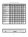
HOW TO PROPERLY ORDER PARTS
In addition to part description and part number, please give model number, serial number, and type of gas used.
MODEL NUMBER
PART DESCRIPTION
Power Cord
Sight Glass Assembly
Sight Glass Cover
Sight Glass Gasket
Burner Box Gasket
Slip Joint Assembly w/Gaskets
Slip Joint Gasket
Slip Joint Ring Gasket
Slip Jt. Ring Gsk. (2 pc. Graphite)
Flue Outlet Pipe Gasket
Air Intake Pipe Gasket
Heat Exchanger Cover Plate
Heat Exchanger Cover Plate Gasket
Burner Box Inlet Gasket
Exhaust Pipe Gasket
Manifold Gasket
Piezo Igniter
Igniter Wire 0.028.508
Spark Igniter SP715, Natural Gas
Spark Igniter SP845, L.P. Gas
Heat Exchanger Kit
Vent Cap Assembly Complete
Vent Cap Spacer Plate Assembly
Vent Cap Mounting Kit
Air Intake Pipe Assembly
Vent Exhaust Pipe Assembly
Elbow 3/8x90 Degree
Air Drop Assembly
Burner Box Bottom Assembly
Burner Access Door
Burner Access Gasket
90 Deg. Pilot Fitting
Pilot Tube Bracket
Vent Terminal Shield
Pilot Tubing w/Fittings
Pilot Tube Gasket
NAT.
DVCF403B-R
DVCF407B-R
DVCF557B-R
L.P.
DVCF404B-R
DVCF408B-R
DVCF558B-R
REF. PART
LIST
PART
LIST
PART
LIST
NO.
NO.
PRICE
NO.
PRICE
NO.
PRICE
N/A
78213
$4.70
78213
$4.70
78213
$4.70
31
43252
$6.50
43252
$6.50
43252
$6.50
32
43258
$1.50
43258
$1.50
43258
$1.50
33
72067
$1.50
72067
$1.50
72067
$1.50
34
72059
$5.90
72059
$5.90
72059
$5.90
50
34220
$27.20
34220
$27.20
34220
$27.20
N/A
72057
$4.70
72057
$4.70
72057
$4.70
61
72056
$2.30
72056
$2.30
72056
$2.30
N/A
72058
$4.70
72058
$4.70
72058
$4.70
36
72055
$1.90
72055
$1.90
72055
$1.90
37
72054
$3.80
72054
$3.80
72054
$3.80
52
34195
$3.60
34195
$3.60
34195
$3.60
38
72053
$1.60
72053
$1.60
72053
$1.60
39
72052
$7.00
72052
$7.00
72052
$7.00
40
72051
$2.30
72051
$2.30
72051
$2.30
55
72068
$1.50
72068
$1.50
72068
$1.50
41
70050
$5.60
N/A
N/A
N/A
N/A
42
72022
$4.70
N/A
N/A
N/A
N/A
43
N/A
N/A
78070
$104.50
78070
$104.50
43
N/A
N/A
78088
$143.30
78088
$143.30
44
34805
$272.40
34805
$272.40
34810
$274.60
45
34250
$127.90
34250
$127.90
34250
$127.90
46
34273
$14.50
34273
$14.50
34273
$14.50
47
34330
$10.70
34330
$10.70
34330
$10.70
48
34280
$28.40
34280
$28.40
34280
$28.40
49
34290
$22.20
34290
$22.20
34290
$22.20
N/A
84501
$2.10
84501
$2.10
84501
$2.10
51
34201
$124.60
34201
$124.60
34630
$140.10
58
34400
$50.90
34400
$50.90
34400
$50.90
56
34425
$11.00
34425
$11.00
34425
$11.00
57
72065
$8.20
72065
$8.20
72065
$8.20
N/A
N/A
N/A
70352
$10.70
70352
$10.70
60
34475
$2.00
34475
$2.00
34475
$2.00
N/A
34950
$60.80
34950
$60.80
34950
$60.80
N/A
78452
$5.40
78452
$5.40
78452
$5.40
59
72063
$1.20
72063
$1.20
72063
$1.20
DVCF653B-R
DVCF654B-R
PART
LIST
NO.
PRICE
78213
$4.70
43252
$6.50
43258
$1.50
72067
$1.50
72059
$5.90
34220
$27.20
72057
$4.70
72056
$2.30
72058
$4.70
72055
$1.90
72054
$3.80
34195
$3.60
72053
$1.60
72052
$7.00
72051
$2.30
72068
$1.50
70050
$5.60
72022
$4.70
N/A
N/A
N/A
N/A
34825
$285.60
34250
$127.90
34273
$14.50
34330
$10.70
34280
$28.40
34290
$22.20
84501
$2.10
34630
$140.10
34400
$50.90
34425
$11.00
72065
$8.20
N/A
N/A
34475
$2.00
34950
$60.80
78452
$5.40
72063
$1.20
Mr. Contractor, we only sell parts through our wholesalers, but the prices listed above are for your
convenience. For prompt parts service, contact the wholesaler from which you purchased your Cozy
heater. NOTE: Parts & schematic drawings on current models are shown at www.cozyheaters.com.
MARCH 2005
Page 20
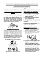
IMPORTANT SAFETY BULLETIN ON YOUR GAS CONTROL AND PILOT LIGHT
SYSTEM FOR HEATING EQUIPMENT
WHAT YOU DON’T KNOW CAN HURT YOU.
Your pilot light system has been designed for safe and reliable operation. Although safety mechanisms are built-in,
the potential for hazard exists. This information is intended to help you avoid these hazards.
YOUR GAS CONTROL AND PILOT LIGHT
SYSTEM
Your gas control and pilot light system has a safety
device whose purpose is to shut-off the gas supply
to the appliance if the pilot light goes out. If you
have trouble lighting the pilot or keeping it lit, it
may mean that this safety device is warning you
that there is a problem with your system.
Inspection and repairs or replacement must be
made by a trained gas service technician.
WHAT TO DO IF YOU SMELL GAS . . .
• Do not try to light any appliance.
• Do not touch any electrical switch; do
not use any phone in your building.
• Immediately call your gas supplier from
a neighbor’s phone. Follow the gas
supplier’s instructions.
• If you cannot reach your gas supplier,
call the fire department.
Installation and service must be performed
by a qualified installer, service agency or the
gas supplier.
Do not store or use gasoline or other
flammable vapors and liquids in the vicinity
of this or any other appliance.
TAMPERING IS DANGEROUS
The pilot safety system may also not work if you
do not follow the lighting instructions carefully or
if you tamper with the gas control that you use to
light the pilot. Tampering with the gas control,
particularly with tools, can damage the safety
mechanism in the control and can allow gas to leak.
This can result in a fire or explosion causing
property damage, personal injury or death.
IF YOU SMELL GAS, DON’T LIGHT IT
IF YOU CAN’T LIGHT IT,
DON’T FIGHT IT!
THIS IS NOT AN ADVERTISEMENT
CRITICAL SAFETY POINTS TO
REMEMBER . . .
• Your gas has been odorized so that you
can smell it. Always smell around for
gas before lighting your appliance.
• Sniff for L.P.-gas at floor level. LP-gas is
heavier than air and may temporarily
exist at floor level.
•
If you smell gas, do not attempt to light
the pilot. Do not cause a spark by
turning on or off electrical switches or
appliances or by using the phone. Turn
off the gas to the appliances and call
your gas supplier from another location.
•
If your gas control has gotten wet as the
result of flooding or other wetting, it
must be replaced immediately by a
trained gas service technician. Water
can lead to damage of the internal safety
mechanism in the gas control and can
create a hazardous condition.
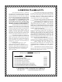
LIMITED WARRANTY
The Louisville Tin & Stove Co. warrants to
the original user the accompanying product for the period
specified herein, provided said product is installed,
operated, maintained, serviced, and used according to
the instructions and specifications accompanying the
product. AS OUTLINED IN OUR INSTRUCTIONS,
ANY WARRANTY CONSIDERATIONS ARE
CONTINGENT ON INSTALLATION BY A
QUALIFIED INSTALLER (CONTRACTOR).
SELF-INSTALLATION IS NOT RECOMMENDED
AND MAY INVALIDATE YOUR WARRANTY.
If within a period of one year from the date of
installation of the product, any part supplied by the
manufacturer proves to be defective due to workmanship
or material, it will replace such part, provided parts have
not been subjected to misuse, alteration, neglect, or
accidents. The term of the warranty for the heat
exchanger is covered in Table A below. Any claim not
made within ten (10) days after the expiration of the
warranty period shall be deemed waived by the user.
The manufacturer shall have no liability or be
required to perform any obligation under this warranty
unless, when requested, the user returns, at the user’s
expense, the component or product claimed defective,
to the manufacturer for inspection, to enable the
manufacturer to determine if the claimed defect is
covered by this warranty.
No charges for freight, labor or other
expenses incurred in the repair, removal, or
replacement of any product or component claimed to
be defective, will be paid by the manufacturer to the
user, and the manufacturer will not be liable for any
expenses incurred, by the user, in remedying any
defect in the product.
Service under this warranty is the responsibility of
the installer. In the event service under this warranty is needed,
the user of the product shall request such service directly from
the installer. If the user is unable to locate the installer, the
user should write directly to the manufacturer, and the name
of an alternative service source will be supplied.
The product safety registration card (packed inside
the appliance) must be completed and returned to the factory.
THIS WARRANTY IS EXPRESSLY IN LIEU OF
ANY OTHER WARRANTIES, EXPRESS OR IMPLIED
(WHETHER WRITTEN OR ORAL). ANY IMPLIED
WARRANTY OF MERCHANTABILITY OR OF FITNESS
FOR A PARTICULAR PURPOSE IS EXPRESSLY LIMITED
TO THE DURATION OF THE MANUFACTURER’S
EXPRESS, WRITTEN WARRANTY.
UNDER NO CIRCUMSTANCES SHALL THE
MANUFACTURER BE LIABLE FOR ANY SPECIAL,
INDIRECT OR CONSEQUENTIAL DAMAGES OR
EXPENSES ARISING DIRECTLY OR INDIRECTLY FROM
ANY COMPONENT OR FROM THE USE THEREOF. THE
REMEDIES SET FORTH HEREIN SHALL BE THE
EXCLUSIVE REMEDIES AVAILABLE TO THE USER AND
ARE IN LIEU OF ALL OTHER REMEDIES.
SOME STATES DO NOT ALLOW LIMITATIONS
ON HOW LONG AN IMPLIED WARRANTY LASTS, SO
THE ABOVE LIMITATIONS MAY NOT APPLY TO YOU.
SOME STATES DO NOT ALLOW THE
EXCLUSION OR LIMITATION OF INCIDENTAL OR
CONSEQUENTIAL DAMAGES, SO THE ABOVE
LIMITATIONS OR EXCLUSIONS MAY NOT APPLY TO
YOU.
THIS WARRANTY GIVES YOU SPECIFIC LEGAL
RIGHTS, AND YOU MAY ALSO HAVE OTHER RIGHTS,
WHICH VARY, FROM STATE TO STATE.
TABLE A
Warranty for gas appliance heat exchangers only.
Product
Warranty Period
Cozy Gas Fired Floor Furnace
Cozy Gas Fired Wall Furnace
Cozy Gas Fired Vented Console Heater
Cozy Gas Fired Direct Vent Heater
Cozy Gas Fired Counterflow Furnace
Cozy Gas Fired Counterflow Direct Vent Furnace
Cozy Gas Fired Mobile Home Direct Vent Furnace
Cozy Gas Fired Hi-Efficient Direct Vent Wall Furnace
10 Years
10 Years
10 Years
10 Years
10 Years
10 Years
10 Years
10 Years
LOUISVILLE TIN AND STOVE COMPANY
P.O. Box 2767
-
Louisville, Kentucky 40201-2767