1
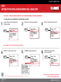
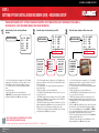
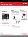
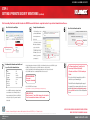
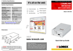
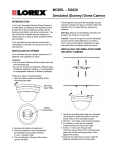
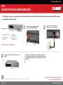
BUSINESS & HOME SECURITY STEP 1 SETTING UP YOUR DIGTIAL VIDEO RECORDER (DVR) * This set-up guide assumes you are connecting cameras (not included with this system) to the Lorex DVR. Consult your DVR’s owners manual for alternative DVR connection and/or information to install a hard drive. 1 Pac k a g e C o n t e n t s 1 - L400 Series Digital Video Recorder 1 - Remote Control 1 - Power Cord 1 - Quick Installation Guide 1 - Owners Manual & Warranty 4 - Rubber Feet (for base) 1 - Need Help Insert 1 - Rack Mount Bracket Kit Connect the cameras (not supplied) to the CH1, CH2, CH3, CH4 Video Inputs (BNC Inputs) BACK OF THE DVR BACK OF THE DVR NOT INCLUDED - CAMERAS / BROADBAND ROUTER 3 Ensure to turn ON the Power switch (located at the front of your DVR). 2 Connect one end of the Power Cord to the DVR; the other end to an electrical outlet Your system is now ready to use. Refer to your DVR’s owner’s manual to learn how to record, playback, use the search features and all other features available with this system. Refer to Step 4 for Setting Up Remote Security Monitoring. FRONT OF THE DVR The number of cameras displayed on submenus will change based on the model of DVR: 4, 8, or 16 channel versions. Information in this document is subject to change without notice. As our products are subject to continuous improvement, Lorex Technology and our subsidiaries reserve the right to modify product design, specifications and prices, without notice and without incurring any obligation. E&OE © 2006 LOREX. All rights reserved. L400 Series Page Version 1.02 NOTE: YOU WILL REQUIRE A PASSWORD TO ACCESS CERTAIN MENU. THE DEFAULT PASSWORD IS 00000000 www.lorexcctv.com BUSINESS & HOME SECURITY STEP 2 SETTING UP YOUR DIGTIAL VIDEO RECORDER (DVR) - BASIC SETUP BASIC SETUP - SETTINGS FOR GENERAL PARAMETERS. CHECK YOUR OWNERS MANUAL FOR DETAILED INFORMATION. Press Menu button & select SYSTEM SET to do the BASIC SETUP of your DVR 1 Language - Displays the current default language on the DVR (English by default). BASIC 2 Initialization - Resets all settings to Factory Default BASIC Language English Initialization Date FormatMM-DD-YYYY Date/Time MM-DD-YYYY Information Save & Exit 3 Date Format - Configures Date Display on the DVR BASIC Language English Initialization Date FormatMM-DD-YYYY Date/Time MM-DD-YYYY Information Save & Exit Language English Initialization Date FormatMM-DD-YYYY Date/Time MM-DD-YYYY Information Save & Exit * ALWAYS REMEMBER TO SAVE YOUR SETTINGS PRIOR TO EXITING THE MENU 4 DATE/TIME - Sets the Date and Time for the unit. BASIC Language English Initialization Date FormatMM-DD-YYYY Date/Time MM-DD-YYYY Information Save & Exit 5 INFORMATION - Displays System Information BASIC HDD Capacity: ## GB / ## GB FPGA Version: ############ Application: ############ RAMDisk Version: ############ Kernel Version: ############ IP Address: ###.###.###.### MAC Address: ##:##:##:##:##:## Language English Initialization Date FormatMM-DD-YYYY Date/Time MM-DD-YYYY Information Save & Exit The number of cameras displayed on submenus will change based on the model of DVR: 4, 8, or 16 channel versions. Information in this document is subject to change without notice. As our products are subject to continuous improvement, Lorex Technology and our subsidiaries reserve the right to modify product design, specifications and prices, without notice and without incurring any obligation. E&OE © 2006 LOREX. All rights reserved. L400 Series Page Version 1.02 6 SAVE & EXIT - Saves any changes made, and exits to the Main Menu. BASIC Language English Initialization Date FormatMM-DD-YYYY Date/Time MM-DD-YYYY Information Save & Exit NOTE: YOU WILL REQUIRE A PASSWORD TO ACCESS CERTAIN MENU. THE DEFAULT PASSWORD IS 00000000 www.lorexcctv.com BUSINESS & HOME SECURITY STEP 3 SETTING UP YOUR DIGTIAL VIDEO RECORDER (DVR) - RECORDING SETUP CAMERA AND RECORDING SETUP - SETTINGS FOR GENERAL PARAMETERS. PRESS MENU BUTTON & SELECT RECORDING SET FOR CAMERA & RECORDING SETUP. CHECK YOUR OWNERS MANUAL FOR DETAILED INFORMATION. 1 Normal Recording - Controls the settings for Manual Recording Normal Recording CH/ FPS CH1 8 CH2 8 CH3 8 CH4 6 Save & Exit /QUALITY MID MID MID MID 2 Alarm Recording - Sets Alarm settings for your DVR Alarm Recording Sensor 1: None Sensor 2 : None Sensor 3 : NC Sensor 4 : NO Alarm Out: Off Save & Exit 1. CH1 - CH4: Lists all available cameras for configuration. Press the and buttons to highlight, and press the buttons to select the FPS or Quality for each CH. Use the and buttons to change the settings, and press SEL to accept the changes: • FPS: A set number of Frames Per Second (total) is divided between all available cameras based on Resolution settings. • QUALITY: Set the quality level for the recording - High, Mid or Low 2. SAVE & EXIT: Saves any changes made, and exits to the Main Menu. Press the and buttons to highlight, and press the SEL button to accept the changes. CH/ FPS /QUALITY CH1 8 HIGH CH2 8 MID CH3 8 LOW CH4 7 OFF Post Alarm Duration: 150 sec. Setup Alarm Save & Exit Alarm 1 : 1 2 Alarm 2 : 3 4 Alarm 3 : 5 6 Alarm 4 : 7 8 Setup Sesnor Save & Exit Sensor 1: None Sensor 2 : None Sensor 3 : NC Sensor 4 : NO Alarm Out: Off Save & Exit 1. CH1-CH4: Lists all available cameras for configuration. Press the and buttons to highlight, and press the SEL button to select the CH#. Use the and and SEL buttons to change the FPS and Quality settings: • FPS: A set number of Frames Per Second (total) is divided between all available cameras based on Resolution settings. • QUALITY: Set the quality level for the recording - High, Mid or Low. 2. POST ALARM: Set the duration that the alarm will continue once detected: 5, 30, 60, 90, 120, 150, 180, 210 or 240 seconds. 3. SETUP ALARM: Configuration sub-menus for Alarm and Sensors. Press the and buttons to highlight, and press the SEL button to access the Alarm Submenu. Use the and buttons to choose the cameras to be associated to each alarm: 4. SETUP SENSOR: Configuration for any Sensors attached to the Alarm block. Press the and buttons to highlight, and press the SEL button to access the Sensor Submenu. Use the and buttons to set the Sensor type: NO (Normally Open), NC (Normally Closed) or None. 5. SAVE & EXIT: Saves any changes made, and exits to the Main Menu. Press the and buttons to highlight, and press the SEL button to accept the changes. NOTE: YOU WILL REQUIRE A PASSWORD TO ACCESS CERTAIN MENU. THE DEFAULT PASSWORD IS 00000000 The number of cameras displayed on submenus will change based on the model of DVR: 4, 8, or 16 channel versions. 3 Motion Recording - Configures for Motion Sensor events Motion Recording CH/ FPS /QUALITY CH1 8 HIGH CH2 8 MID CH3 8 LOW CH4 7 LOW Post Motion Duration: 150 sec. Setup Motion Save & Exit CH/ AREA/ SENSE CH1 AREA HIGH CH2 AREA MID CH3 AREA LOW CH4 AREA OFF Save & Exit 1. CH1 - CH4: Lists all available cameras for configuration. Press the and buttons to highlight, and press the buttons to select the FPS or Quality for each CH. Use the and buttons to change the settings, and press SEL to accept the changes: • FPS: A set number of Frames Per Second (total) is divided between all available cameras based on Resolution settings.: • QUALITY: Set the quality level for the recording - High, Mid, Low or Off 2. POST MOTION DURATION: Set the duration that the alarm will continue once detected: 5, 30, 60, 90, 120, 150, 180, 210 or 240 seconds. 3. SETUP MOTION: Configuration for each Motion Sensor enabled Camera Press the and buttons to highlight the Setup Motion option, and press the SEL button to access the SETUP MOTION submenu. Press the and buttons to highlight a specific Camera, and press the SEL button to select. • AREA: Press the SEL button on the AREA option to specify segments of the Camera view to have Motion Detection. Use the and buttons to navigate around the Motion Setup screen, and press the SEL button to turn a segment ON/OFF. Press the MENU button once complete. Dark Blue indicates that a section has been selected for motion detection, and blank areas indicate that motion will not be detected in those areas. • SENSE: Sets the Sensitivity of the Motion Detection: Use the and and SEL buttons to change the setting to High, Mid, Low or Off. 4. SAVE & EXIT: Saves any changes made, and exits to the Main Menu. Press and buttons to highlight, and press the SEL button to accept the changes. Information in this document is subject to change without notice. As our products are subject to continuous improvement, Lorex Technology and our subsidiaries reserve the right to modify product design, specifications and prices, without notice and without incurring any obligation. E&OE © 2006 LOREX. All rights reserved. L400 Series Page Version 1.02 www.lorexcctv.com BUSINESS & HOME SECURITY STEP 3 SETTING UP YOUR DIGTIAL VIDEO RECORDER (DVR) - RECORDING SETUP (continued) CAMERA AND RECORDING SETUP - SETTINGS FOR GENERAL PARAMETERS. PRESS MENU BUTTON & SELECT RECORDING SET FOR CAMERA & RECORDING SETUP. CHECK YOUR OWNERS MANUAL FOR DETAILED INFORMATION. 4 5 Schedule Recording - Configures for Scheduled events Schedule Recording CH/ FPS /QUALITY CH1 8 HIGH CH2 8 MID CH3 8 LOW CH4 7 OFF Setup Schedule Save & Exit 1. CH1 - CH4: Lists all available cameras for configuration. Press the and buttons to highlight, and press the buttons to select the FPS or Quality for each CH. Use the the and buttons to change the settings, and press SEL to accept the changes: • FPS: A set number of Frames Per Second (total) is divided between all available cameras based on Resolution settings. • QUALITY: Set the quality level for the recording - High, Mid, Low 2. SETUP SCHEDULE: Settings for scheduled recording times. Press the and buttons to highlight, and press the SEL button to access the Schedule Setup Submenu: • Use the and buttons to choose a day (SUN-SAT) and SEL to set the schedule. • Use the and buttons to set the recording Start Time and End Time • Select SAVE & EXIT to return to the Menu SUN MON TUE WED THU FRI SAT Save & Exit FROM 00:00 00:00 00:00 00:00 00:00 00:00 00:00 TO 00:00 00:00 00:00 00:00 00:00 00:00 00:00 Recording ON/OFF - Controls the Recording for Event Types Recording ON/OFF Alarm Rec: Motion Rec: Schedule Rec: Save & Exit OFF OFF OFF ALARM RECORDING: Turns Alarm Recording ON/OFF. Press the and buttons to highlight, and press the buttons to switch between ON and OFF. MOTION RECORDING: Turns Motion Recording ON/OFF. Press the and buttons to highlight, and press the buttons to switch between ON and OFF. SCHEDULE RECORDING: Turns Schedule Recording ON/OFF. Press the and buttons to highlight, and press the buttons to switch between ON and OFF. SAVE & EXIT: Saves any changes made, and exits to the Main Menu. Press the and buttons to highlight, and press the SEL button to accept the changes. Note: After setting the Normal, Alarm, Motion, Schedule Recording, RECORDING ON/OFF MUST BE set to ON individually to activate the functions. 3. SAVE & EXIT: Saves any changes made, and exits to the Main Menu. Press the and buttons to highlight, and press the SEL button to accept the changes. The number of cameras displayed on submenus will change based on the model of DVR: 4, 8, or 16 channel versions. Information in this document is subject to change without notice. As our products are subject to continuous improvement, Lorex Technology and our subsidiaries reserve the right to modify product design, specifications and prices, without notice and without incurring any obligation. E&OE © 2006 LOREX. All rights reserved. L400 Series Page Version 1.02 NOTE: YOU WILL REQUIRE A PASSWORD TO ACCESS CERTAIN MENU. THE DEFAULT PASSWORD IS 00000000 www.lorexcctv.com BUSINESS & HOME SECURITY STEP 4 SETTING UP REMOTE SECURITY MONITORING Port forwarding Your Router and the Creation of a DDNS Account with Lorex is required in order for you to have Remote Internet Access. 1 Connect one end of ethernet cable (not supplied) to the DVR, the other end to the broadband router (not included). Power router and DVR ON if not already ON BACK OF A ROUTER (NOT INCLUDED) 2 Record the MAC and IP Address(s) NETWORK SET This submenu allows you to change the NETWORK options for the DVR unit. The op- 3 Open your Web Browser. Enter http://ddns.strategicvista.net http://ddns.strategicvista.net tions in the DDNS Set menu control access to the DVR using the free DDNS, and the options in the IP Set section controls local network settings for local access to the DVR. To obtain the DVR’s IP and MAC address, press the INFO button from the DVR Remote Control. Page 45 on your owners manual will have additional network instructions. NETWORK SET DDNS SET IP SET BACK OF THE DVR NOTE: Go to MENU from under NETWORK SET and select IP SET and set the DHCP to YES. Save and Exit and allow few seconds for the unit to obtain an IP Address from the Router. Please note down the IP and MAC Address(s) for further use on the DVR. DHCP: YES IP Address: ###.###.###.### Gateway: ###.###.###.### Netmask: ###.###.###.### DNS Server: ###.###.###.### DVR Port: 2000 Webserver Port: 0080 Save & Exit DDNS SET The options in the DDNS Set menu allow the DVR unit to be accessed remotely using the Free DDNS Server and the internet. All information will need to be manually entered based on information from the free DDNS Setup (see page 48 for details).Set the USE DYNAMIC IP option to YES if you will be using the Free DNS Website service to connect to your DVR. The number of cameras displayed on submenus will change based on the model of DVR: 4, 8, or 16 channel versions. Information in this document is subject to change without notice. As our products are subject to continuous improvement, Lorex Technology and our subsidiaries reserve the right to modify product design, specifications and prices, without notice and without incurring any obligation. E&OE © 2006 LOREX. All rights reserved. L400 Series Page Version 1.02 NOTE: YOU WILL REQUIRE A PASSWORD TO ACCESS CERTAIN MENU. THE DEFAULT PASSWORD IS 00000000 www.lorexcctv.com BUSINESS & HOME SECURITY STEP 4 SETTING UP REMOTE SECURITY MONITORING (continued) Port forwarding Your Router and the Creation of a DDNS Account with Lorex is required in order for you to have Remote Internet Access. 4 Select the Create Account Option 5 6 Complete Account Information 1. For Product License: Select your Product Model Number Select the Create New Account Link from the drop down menu (L400 Series) 2. For Product Code enter the MAC address (without any space) recorded earlier Create Account 3. For URL Request choose a URL Name (not to exceed 15 characters) (e.g. your name, your company etc.) 7 An Automated Confirmation email will be sent to you. Record the information below DDNS: Domain name: User name: Password: DDNS Status: Web Port: Video Port: Save & Exit YES house JohnDoe <enter the password> Check 80 2000 Once the DDNS Account has been configured (and the account details are received in Email), then these settings can be added to the DVR unit. See the DDNS Set menu options on Page 35 of your owner’s manual for 1 3 2 1. Press the Menu button on the front panel of the DVR. Select the Network Set option, and select the DDNS Set option. • Set DDNS to YES (if using remote access to the DVR. Otherwise, leave this option as NO). • Setup the Domain Name, User Name and Password manually, based on the settings received in email. • Select the DDNS Status Check to confirm that the DDNS Service can be reached. CHECKING DDNS NOW Please wait.. . It may take a few minutes 2. Select SAVE & EXIT to save the changes. If your information is correct the system will display the following message: DDNS STATUS OK Move the cursor to “Save & Exit” and press the select button. Press the menu button a few times to exit the menu 8 Port Forward your Router. You will need to Forward ports 2000 and 80 (default). All routers are different. To Port Forward your Router: Refer to your Router’s manual for specific instructions on port forwarding (or) Check the Router configuration guide support document in the consumer guide section on our website http://lorexstore.strategicvista.com/article.aspx?aid=3 and select Router Configuration Guide further details. The number of cameras displayed on submenus will change based on the model of DVR: 4, 8, or 16 channel versions. Information in this document is subject to change without notice. As our products are subject to continuous improvement, Lorex Technology and our subsidiaries reserve the right to modify product design, specifications and prices, without notice and without incurring any obligation. E&OE © 2006 LOREX. All rights reserved. L400 Series Page Version 1.02 NOTE: YOU WILL REQUIRE A PASSWORD TO ACCESS CERTAIN MENU. THE DEFAULT PASSWORD IS 00000000 www.lorexcctv.com BUSINESS & HOME SECURITY STEP 4 SETTING UP REMOTE SECURITY MONITORING (continued) Port forwarding Your Router and the Creation of a DDNS Account with Lorex is required in order for you to have Remote Internet Access. 9 Accessing the DVR Locally / Remotely with a PC Once the DVR and the Local Network have been successfully configured, a connection can be made with a Local PC (a PC within the same network as the DVR), or remotely (a PC from outside the network via the Internet) using Microsoft Internet Explorer. 10 Logging Into Live Monitoring Once the Web Client application has loaded through Internet Explorer, a pop-up window will appear. Log in as: Local: (IF ON THE SAME ROUTER) • Username: admin Use the internal network IP address which you recorded earlier. For Example: • Password: 00000000 (may be different if the default system password on your DVR was • http://192.168.0.150 (example) Remote: (IF NOT ON THE SAME ROUTER) changed) Use either the external IP address or the DDNS name, as well as the Web Server port. For Example: • http://216.15.59.221 (example) • http://tomsmith.strategicvista.net Internet Explorer Settings - Installation of Active X Controls and Allowing POP-UPS are necessary. To correctly load the Web Client Software, the security settings in Internet Explorer may need to be adjusted. Please check your owner’s manual for detailed instruction on setting your Internet Explorer. The Web Client software will load once the Login has been completed successfully. Failure to It’s all on the web login correctly will close the Web Client window. NOTE: YOUR COMPUTER MUST BE CONNECTED TO THE SAME ROUTER THAT YOU HAVE YOUR DVR CONNECTED. SETUP Product Information Specification Sheets User Manuals Software Updates Quick Start Guides Firmware Upgrades CONNECT FOR ADDITIONAL INFORMATION OR TROUBLESHOOTING HELP, REFER TO YOUR OWNERS MANUAL FOR ASSISTANCE. YOU CAN ALSO CALL OR EMAIL FOR FURTHER SUPPORT. TOLL FREE TECHNICAL SUPPORT: 1-888-42 LOREX (1-888-425-6739) Press the Connect Button to view the Camera images NOTE: YOU WILL REQUIRE A PASSWORD TO ACCESS CERTAIN MENU. THE DEFAULT PASSWORD IS 00000000 The number of cameras displayed on submenus will change based on the model of DVR: 4, 8, or 16 channel versions. EMAIL SUPPORT: [email protected] WEBSITE: WWW.LOREXCCTV.COM Information in this document is subject to change without notice. As our products are subject to continuous improvement, Lorex Technology and our subsidiaries reserve the right to modify product design, specifications and prices, without notice and without incurring any obligation. E&OE © 2006 LOREX. All rights reserved. L400 Series Page Version 1.02 www.lorexcctv.com