1
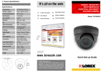
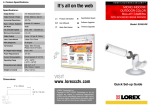
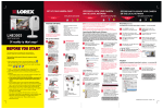
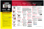
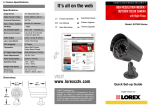
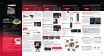
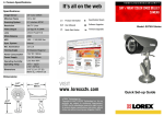
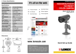
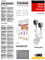
4. Specifications
HOME & BUSINESS SECURITY
It’s all on the web
Switcher Specifications:
Channels
2
Scan Time
1~30 Seconds
Operating Voltage
9V DC 300mA
Camera Input
2 DIN
AV Output
1 DIN
Power Supply
DC 9V DC 300mA
Operating Humidity
90% HM Max.
Operating Temp
14°F ~ 122°F
(-10°~ 50°C)
Product Information
Specification Sheets
User Manuals
Software Upgrades
Quick Start Guides
Firmware Upgrades
2 CHANNEL MINI
SWITCHER BOX
WITH 2 COLOR CAMERAS
Model: SHS-2S6183W
Camera Specifications:
Image Sensor
1/4” Color CMOS
Video Format / Pixels
NTSC: 510(H) x 492 (V)
Horizontal Resolution
330 TVL
Sync. & Scan. Systems
Internal; 2:1 Interlace
White Balance
ATW
Shutter Speed
1/60 ~ 1/15,000 sec.
Iris
AES
Minimum Illumination
3.0 LUX
Lens
3.6mm F2.0/ Fixed
FOV (Diagonal)
70 Degree
Termination
Video/Audio/Power: 6-Pin
DIN Plug
IR / Night Vision Range
8 IR LED 850nm; 8ft. / 2.5m
Power Requirement
9V DC
Power Consumption
Less than 130mA @ 9V DC
Operating Temp
14°F ~ 113°F
(-10°C ~ 45°C)
Dimensions (with stand)
(H x D x W)
3.7” x 2.8” x 3.4”
95mm x 71mm x 34mm
Weight
200g / 7.05 oz.
VISIT
www.lorexcctv.com
LOREX Technology Inc.
Copyright © 2007 LOREX Technology Inc. As our
products are subject to continuous improvement,
LOREX and its subsidiaries reserve the right to modify product design, specifications and prices, without
notice and without incurring any obligation. E&OE
Quick Set-up Guide
1. Package Contents
1 x Mini Switcher Box
2. Switcher Controls
2 x DIN Cameras
2 x Camera Stands
2 x 60’ Extension Cables
1. Connect the 60ft (18m) DIN Extension cable to the
Switcher. Run the cable as desired, and connect the
other end of the 60ft (18m) Extension Cable to the DIN
Camera (see Setup Diagram below).
1
2
1 x Power Adaptor
1 x AV Cable
1 x Velcro Adhesive Strip
3. Camera Connections
3
1. SCAN TIME SETTING - Turn to adjust the lenth of time
that each camera is displayed onscreen before switching to
the next camera. The sequence time can be set between
1~30 Seconds (when in SCAN View Mode).
2. CHANNEL SELECT - Move the switch to change the
onscreen view to CH1, CH2 or SCAN View Mode.
3. STATUS INDICATOR LEDs - The Red LED light
indicates that the unit is in Scan Mode; The Green LED
lights indicate the currently displayed channel (CH1 or
CH2).
Switcher Features:
•
•
•
Easily connects to any TV, VCR or Monitor
Compact design
Easy mounting with Velcro strip (included)
5
Durable Metal Camera ideal for indoor or outdoor use *
Night Vision provides viewing in low light conditions **
View as well as listen with camera's built-in
microphone.
* Not recommended for direct exposure to rain or snow
** IR illumination range of 8ft. / 2.5m under ideal conditions. Objects at or beyond this range may be partially or completely obscured, depending on the
camera application.
Dimensions:
2. Attach the camera to the supplied stand. Mount the
camera stand to the desired mounting surface
NOTE: Confirm that the arrows on the DIN Extension
cable are aligned with the Camera Cable and Observation
system ports when connecting the cable. If the pins in the
DIN Cable are bent, the Camera will NOT function
3. Connect the DIN end of the A/V Cable to the switcher.
Connect the RCA end to the corresponding color ports
on the TV or VCR:
•Yellow Cable: RCA Video
•White Cable: RCA Audio
4. Connect the Power Adaptor to the switcher.
Camera Features:
•
•
•
NOTE: Cameras with 6 Pin DIN
connections draw power from the Switcher.
Additional power adaptors are not needed
for these cameras.
4
6
4. DC POWER PORT - Connection port for the Power
Adaptor.
5. A/V OUT DIN PORT - Sends the outgoing video/audio
signal to a TV or VCR.
6. CH1~CH2 DIN PORTS - Receives the audio and video
signal from the Cameras.
NOTE: Test the cameras prior to selecting a
permanent mounting location by temporarily
connecting the Cameras and Cables to the switcher.
NOTE: This camera is designed to work with a 9V
Power Adaptor ONLY. Use of this camera with any
other system may damage the camera and invalidate
the warranty.
Setup Diagram: